1998 DODGE RAM 1500 Transfer case
[x] Cancel search: Transfer casePage 61 of 2627

INSTALLATION
INSTALLATION - 4X4
(1) Install the stabilizer link to the vehicle.
(2) Install the lower nut and Tighten to 102 N´m
(75 ft. lbs.).
(3) Install the retainers, grommets and upper nut
and Tighten to 38 N´m (27 ft. lbs.).
(4) Remove the support and lower the vehicle.
INSTALLATION - 4X2
(1) Install the stabilizer link to the vehicle (Fig.
29).
(2) Install the lower nut and Tighten to 102 N´m
(75 ft. lbs.).
(3) Install the retainers, grommets and upper nut
and Tighten to 38 N´m (27 ft. lbs.).
(4) Remove the support and lower the vehicle.
TORSION BAR
DESCRIPTION
The front of the bar connects to the back side of
the lower suspension arm. The rear end of the bar is
mounted in a anchor that rests in the frame cross-
member.
OPERATION
The torsion bars are used to control ride height
and ride quality. The vehicle height is adjusted
through an anchor adjustment bolt that increases or
decreases the wind up of the torsion bar. Increasing
or decreasing the bar angle changes the wind up of
the suspension arms.
REMOVAL
CAUTION: The left and right side torsion bars are
NOT interchangeable. The bars are identified and
stamped R or L, for right or left. The bars do not
have a front or rear end and can be installed with
either end facing forward.
(1) Raise and support the vehicle with the front
suspension hanging.
(2) Remove the transfer case skid plate (Refer to
13 - FRAME & BUMPERS/FRAME/TRANSFER
CASE SKID PLATE - REMOVAL).
NOTE: Count and record the number of turns for
installation reference.
(3) Mark the adjustment bolt setting.
(4) Install Special Tool - 8686 to the anchor arm
and the cross member (Fig. 30).(5) Increase the tension on the anchor arm tool
until the load is removed from the adjustment bolt
and the adjuster nut (Fig. 30).
(6) Turn the adjustment bolt counterclockwise to
remove the bolt and the adjuster nut..
(7) Remove the Special Tool - 8686, allowing the
torsion bar to unload (Fig. 30).
(8) Remove torsion bar and anchor. Remove anchor
from torsion bar (Fig. 31).
(9) Remove all foreign material from torsion bar
mounting in anchor and suspension arm.
(10) Inspect adjustment bolt, bearing and swivel
for damage.
Fig. 30 LOADING/UNLOADING TORSION BAR
1 - SPECIAL TOOL ± 8686
2 - CROSSMEMBER
Fig. 31 TORSION BAR
1 - ANCHOR
2 - SWIVEL
3 - TORSION BAR
4 - LOWER CONTROL ARM
2 - 26 FRONT - INDEPENDENT FRONT SUSPENSIONDR
STABILIZER LINK (Continued)
Page 62 of 2627

INSTALLATION
CAUTION: The left and right side torsion bars are
NOT interchangeable. The bars are identified and
stamped R or L, for right or left. The bars do not
have a front or rear end and can be installed with
either end facing forward.
(1) Insert torsion bar ends into anchor and suspen-
sion arm.
(2) Position the anchor in the frame crossmember.
(3) Install Special Tool - 8686 to the anchor and
the crossmember (Fig. 30).
(4) Increase the tension on the anchor in order to
load the torsion bar.
(5) Install the adjustment bolt and the adjuster
nut.
(6) Turn adjustment bolt clockwise the recorded
amount of turns.
(7) Remove tool - 8686 from the torsion bar cross-
member (Fig. 30).
(8) Install the transfer case skid plate (Refer to 13
- FRAME & BUMPERS/FRAME/TRANSFER CASE
SKID PLATE - INSTALLATION).
(9) Lower vehicle and adjust the front suspension
height (Refer to 2 - SUSPENSION/WHEEL ALIGN-
MENT - STANDARD PROCEDURE).
(10) Perform a wheel alignment (Refer to 2 - SUS-
PENSION/WHEEL ALIGNMENT - STANDARD
PROCEDURE).
UPPER BALL JOINT
DIAGNOSIS AND TESTING - UPPER BALL
JOINT
NOTE: If the ball joint is equipped with a lubrication
fitting, grease the joint then road test the vehicle
before performing test.
(1) Raise the front of the vehicle. Place safety floor
stands under both lower control arms as far outboard
as possible. Lower the vehicle to allow the stands to
support some or all of the vehicle weight.
(2) Remove the front tires.(3) Mount a dial indicator solidly to the frame and
then zero the dial indicator.
(4) Position dial indicator plunger on the topside of
the upper ball joint (Fig. 32).
NOTE: The dial indicator plunger must be perpen-
dicular to the machined surface of the ball joint
(Fig. 32).
NOTE: Use care not to pry or tear the ball joint
boot, when checking the free play.
(5) Position a pry bar between the steering
knuckle and the upper control arm. Pry upwards on
the upper control arm (Fig. 32).
(6) If the travel exceeds 0.5 mm (0.020 in.), replace
the upper control arm since the upper ball joint is
integral to the arm (Refer to 2 - SUSPENSION/
FRONT/UPPER CONTROL ARM - REMOVAL).
(7) If the upper ball joint is within specs reinstall
the front tires (Refer to 22 - TIRES/WHEELS/
WHEELS - STANDARD PROCEDURE).
Fig. 32 UPPER BALL JOINT PLAY
1 - DIAL INDICATOR
2 - UPPER CONTROL ARM
3-PRYBAR
4 - KNUCKLE
5 - BALL JOINT BOOT
DRFRONT - INDEPENDENT FRONT SUSPENSION 2 - 27
TORSION BAR (Continued)
Page 83 of 2627

DRIVELINE VIBRATION
Drive Condition Possible Cause Correction
Propeller Shaft Noise 1) Undercoating or other foreign
material on shaft.1) Clean exterior of shaft and wash
with solvent.
2) Loose U-joint clamp screws. 2) Install new clamps and screws
and tighten to proper torque.
3) Loose or bent U-joint yoke or
excessive runout.3) Install new yoke.
4) Incorrect driveline angularity. 4) Measure and correct driveline
angles.
5) Rear spring center bolt not in
seat.5) Loosen spring u-bolts and seat
center bolt.
6) Worn U-joint bearings. 6) Install new U-joint.
7) Propeller shaft damaged or out
of balance.7) Installl new propeller shaft.
8) Broken rear spring. 8) Install new rear spring.
9) Excessive runout or unbalanced
condition.9) Re-index propeller shaft, test,
and evaluate.
10) Excessive drive pinion gear
shaft runout.10) Re-index propeller shaft and
evaluate.
11) Excessive axle yoke deflection. 11) Inspect and replace yoke if
necessary.
12) Excessive transfer case runout. 12) Inspect and repair as necessary.
Universal Joint Noise 1) Loose U-joint clamp screws. 1) Install new clamps and screws
and tighten to proper torque.
2) Lack of lubrication. 2) Replace as U-joints as
necessary.
PROPELLER SHAFT BALANCE
If propeller shaft is suspected of being out of bal-
ance, use the following procedure.
NOTE: Indexing propeller shaft 180É relative to the
yoke may eliminate some vibrations.
(1) Raise and support vehicle.
(2) Clean all foreign material from the propeller
shaft and universal joints.
(3) Inspect propeller shaft for missing balance
weights, broken welds and bent areas.If propeller
shaft is bent, it must be replaced.
(4) Inspect universal joints for wear and properly
installed.
(5) Check propeller shaft bolt torques.
(6) Remove wheels and install lug nuts to retain
brake rotors.
(7) Mark and number the shaft six inches from the
pinion yoke end at four positions 90É apart.
(8) Run and accelerate vehicle until vibration
occurs. Note the intensity and speed the vibration
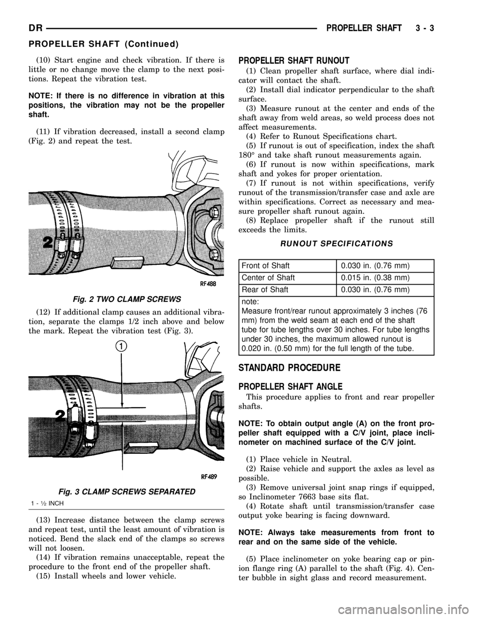
occurred. Stop the engine.(9) Install a screw clamp at position 1 (Fig. 1).
Fig. 1 CLAMP SCREW AT POSITION 1
1 - CLAMP
2 - SCREWDRIVER
3 - 2 PROPELLER SHAFTDR
PROPELLER SHAFT (Continued)
Page 84 of 2627

(10) Start engine and check vibration. If there is
little or no change move the clamp to the next posi-
tions. Repeat the vibration test.
NOTE: If there is no difference in vibration at this
positions, the vibration may not be the propeller
shaft.
(11) If vibration decreased, install a second clamp
(Fig. 2) and repeat the test.
(12) If additional clamp causes an additional vibra-
tion, separate the clamps 1/2 inch above and below
the mark. Repeat the vibration test (Fig. 3).
(13) Increase distance between the clamp screws
and repeat test, until the least amount of vibration is
noticed. Bend the slack end of the clamps so screws
will not loosen.
(14) If vibration remains unacceptable, repeat the
procedure to the front end of the propeller shaft.
(15) Install wheels and lower vehicle.PROPELLER SHAFT RUNOUT
(1) Clean propeller shaft surface, where dial indi-
cator will contact the shaft.
(2) Install dial indicator perpendicular to the shaft
surface.
(3) Measure runout at the center and ends of the
shaft away from weld areas, so weld process does not
affect measurements.
(4) Refer to Runout Specifications chart.
(5) If runout is out of specification, index the shaft
180É and take shaft runout measurements again.
(6) If runout is now within specifications, mark
shaft and yokes for proper orientation.
(7) If runout is not within specifications, verify
runout of the transmission/transfer case and axle are
within specifications. Correct as necessary and mea-
sure propeller shaft runout again.
(8) Replace propeller shaft if the runout still
exceeds the limits.
RUNOUT SPECIFICATIONS
Front of Shaft 0.030 in. (0.76 mm)
Center of Shaft 0.015 in. (0.38 mm)
Rear of Shaft 0.030 in. (0.76 mm)
note:
Measure front/rear runout approximately 3 inches (76
mm) from the weld seam at each end of the shaft
tube for tube lengths over 30 inches. For tube lengths
under 30 inches, the maximum allowed runout is
0.020 in. (0.50 mm) for the full length of the tube.
STANDARD PROCEDURE
PROPELLER SHAFT ANGLE
This procedure applies to front and rear propeller
shafts.
NOTE: To obtain output angle (A) on the front pro-
peller shaft equipped with a C/V joint, place incli-
nometer on machined surface of the C/V joint.
(1) Place vehicle in Neutral.
(2) Raise vehicle and support the axles as level as
possible.
(3) Remove universal joint snap rings if equipped,
so Inclinometer 7663 base sits flat.
(4) Rotate shaft until transmission/transfer case
output yoke bearing is facing downward.
NOTE: Always take measurements from front to
rear and on the same side of the vehicle.
(5) Place inclinometer on yoke bearing cap or pin-
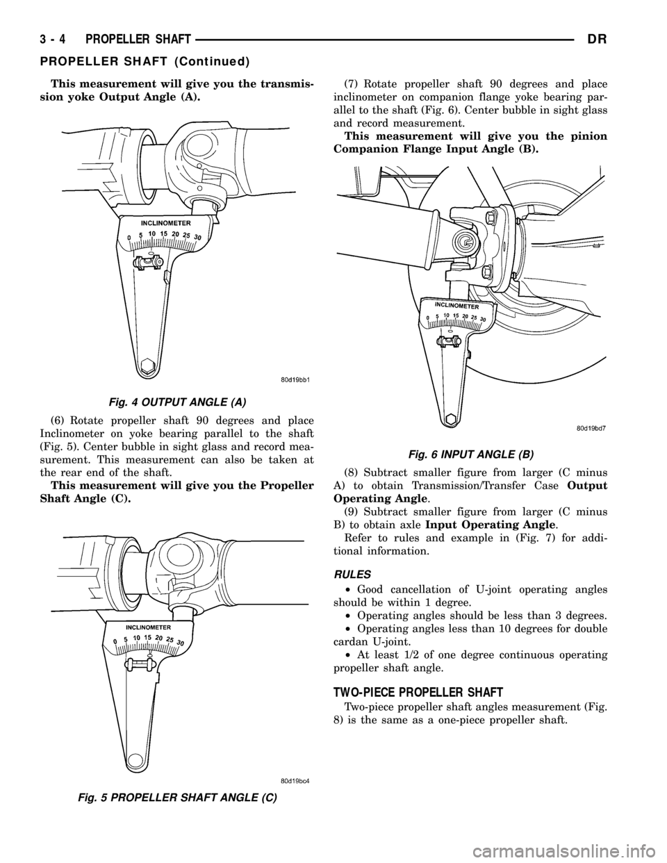
ion flange ring (A) parallel to the shaft (Fig. 4). Cen-
ter bubble in sight glass and record measurement.
Fig. 2 TWO CLAMP SCREWS
Fig. 3 CLAMP SCREWS SEPARATED
1-1¤2INCH
DRPROPELLER SHAFT 3 - 3
PROPELLER SHAFT (Continued)
Page 85 of 2627

This measurement will give you the transmis-
sion yoke Output Angle (A).
(6) Rotate propeller shaft 90 degrees and place
Inclinometer on yoke bearing parallel to the shaft
(Fig. 5). Center bubble in sight glass and record mea-
surement. This measurement can also be taken at
the rear end of the shaft.
This measurement will give you the Propeller
Shaft Angle (C).(7) Rotate propeller shaft 90 degrees and place
inclinometer on companion flange yoke bearing par-
allel to the shaft (Fig. 6). Center bubble in sight glass
and record measurement.
This measurement will give you the pinion
Companion Flange Input Angle (B).
(8) Subtract smaller figure from larger (C minus
A) to obtain Transmission/Transfer CaseOutput
Operating Angle.
(9) Subtract smaller figure from larger (C minus
B) to obtain axleInput Operating Angle.
Refer to rules and example in (Fig. 7) for addi-
tional information.
RULES
²Good cancellation of U-joint operating angles
should be within 1 degree.
²Operating angles should be less than 3 degrees.
²Operating angles less than 10 degrees for double
cardan U-joint.
²At least 1/2 of one degree continuous operating
propeller shaft angle.
TWO-PIECE PROPELLER SHAFT
Two-piece propeller shaft angles measurement (Fig.
8) is the same as a one-piece propeller shaft.
Fig. 4 OUTPUT ANGLE (A)
Fig. 5 PROPELLER SHAFT ANGLE (C)
Fig. 6 INPUT ANGLE (B)
3 - 4 PROPELLER SHAFTDR
PROPELLER SHAFT (Continued)
Page 87 of 2627

SPECIFICATIONS
TORQUE SPECIFICATIONS
DESCRIPTION N´m Ft. Lbs. In. Lbs.
Center Bearing Bolts 54 40 -
Transfer Case Flange
Bolts88 65 -
LD - Front Pinion Flange
Bolts11 5 8 5 -
HD - Front Pinion Flange
Bolts28 21 -
Rear Pinion Flange Bolts 115 85 -
Rear Pinion Yoke Bolts 29 22 -
SPECIAL TOOLSPROPELLER SHAFT- LD
FRONT
REMOVAL
(1) With vehicle in neutral, position vehicle on
hoist.
(2) Remove exhaust crossover pipe.
(3) Mark a line across the axle companion flange,
propeller shaft flange yoke and transfer case (Fig. 9)
for installation reference.
INCLINOMETER 7663
Bearing Splitter 1130
INSTALLER 6052
Fig. 9 COMPANION FLANGE
1 - COMPANION FLANGE
2 - PROPELLER SHAFT
3 - FLANGE YOKE
4 - REFERENCE MARK
3 - 6 PROPELLER SHAFTDR
PROPELLER SHAFT (Continued)
Page 88 of 2627

(4) Remove axle/transfer case companion flange
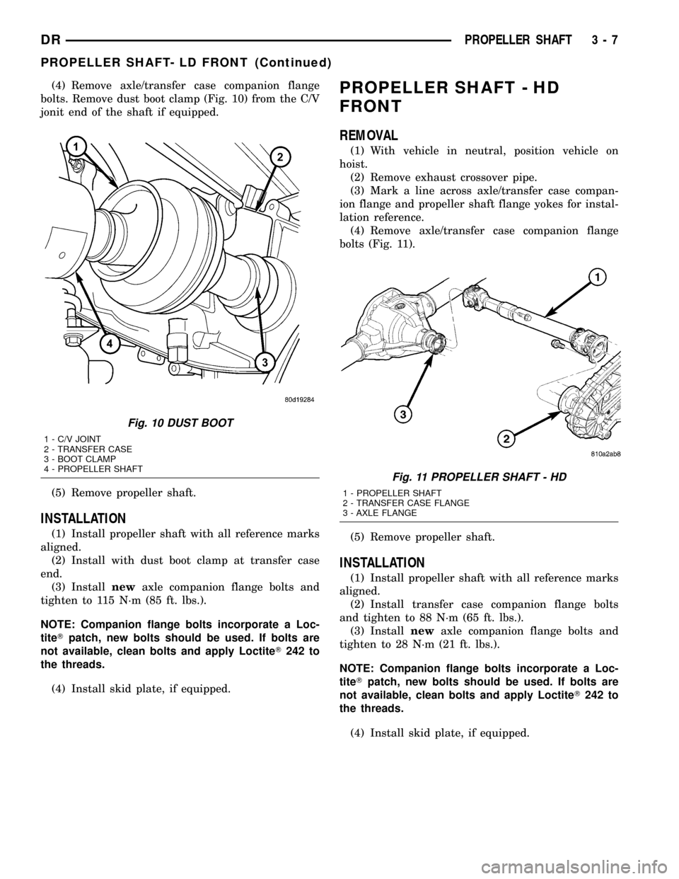
bolts. Remove dust boot clamp (Fig. 10) from the C/V
jonit end of the shaft if equipped.
(5) Remove propeller shaft.
INSTALLATION
(1) Install propeller shaft with all reference marks
aligned.
(2) Install with dust boot clamp at transfer case
end.
(3) Installnewaxle companion flange bolts and
tighten to 115 N´m (85 ft. lbs.).
NOTE: Companion flange bolts incorporate a Loc-
titeTpatch, new bolts should be used. If bolts are
not available, clean bolts and apply LoctiteT242 to
the threads.
(4) Install skid plate, if equipped.
PROPELLER SHAFT - HD
FRONT
REMOVAL
(1) With vehicle in neutral, position vehicle on
hoist.
(2) Remove exhaust crossover pipe.
(3) Mark a line across axle/transfer case compan-
ion flange and propeller shaft flange yokes for instal-
lation reference.
(4) Remove axle/transfer case companion flange
bolts (Fig. 11).
(5) Remove propeller shaft.
INSTALLATION
(1) Install propeller shaft with all reference marks
aligned.
(2) Install transfer case companion flange bolts
and tighten to 88 N´m (65 ft. lbs.).
(3) Installnewaxle companion flange bolts and
tighten to 28 N´m (21 ft. lbs.).
NOTE: Companion flange bolts incorporate a Loc-
titeTpatch, new bolts should be used. If bolts are
not available, clean bolts and apply LoctiteT242 to
the threads.
(4) Install skid plate, if equipped.
Fig. 10 DUST BOOT
1 - C/V JOINT
2 - TRANSFER CASE
3 - BOOT CLAMP
4 - PROPELLER SHAFT
Fig. 11 PROPELLER SHAFT - HD
1 - PROPELLER SHAFT
2 - TRANSFER CASE FLANGE
3 - AXLE FLANGE
DRPROPELLER SHAFT 3 - 7
PROPELLER SHAFT- LD FRONT (Continued)
Page 89 of 2627

REAR PROPELLER SHAFT
REMOVAL
(1) With vehicle in neutral, position vehicle on
hoist.
(2) Mark pinion flange or yoke and propeller shaft
flange or yoke (Fig. 12) for installation reference.
(3) Mark the outline of the center bearing (Fig. 13)
on the crossmember for installation reference, if
equipped.
(4) Remove center bearing mounting nuts, if
equipped.
(5) Remove pinion flange or yoke clamp bolts.
(6) Slide propeller shaft off transmission or trans-
fer case and remove shaft.
INSTALLATION
(1) Slide slip yoke onto the transmission/transfer
case output shaft.
(2) Align and install center bearing on crossmem-
ber, if equipped and tighten nuts to 54 N´m (40 ft.
lbs.).
(3) Align reference marks on propeller shaft and
pinion flange or pinon yoke.(4) Installnewbolts and tighten to:
²(Fig. 14) Companion flange bolts 15 N´m (85 ft.
lbs.)
²(Fig. 15) Yoke clamp bolts 29 N´m (22 ft. lbs.)
NOTE: Companion flange bolts incorporate a Loc-
titeTpatch, new bolts should be used. If bolts are
not available, clean bolts and apply LoctiteT242 to
the threads.
Fig. 12 COMPANION FLANGE
1 - PROPELLER SHAFT
2 - COMPANION FLANGE
3 - REFERENCE MARK
4 - SHAFT FLANGE YOKE
Fig. 13 CENTER BEARING
1 - CENTER BEARING
2 - DUST BOOT
3 - MOUNTING NUTS
Fig. 14 REAR PROPELLER SHAFT
1 - COMPANION FLANGE
2 - PROPELLER SHAFT
3 - 8 PROPELLER SHAFTDR