1998 DODGE RAM 1500 Front hood
[x] Cancel search: Front hoodPage 1161 of 2627
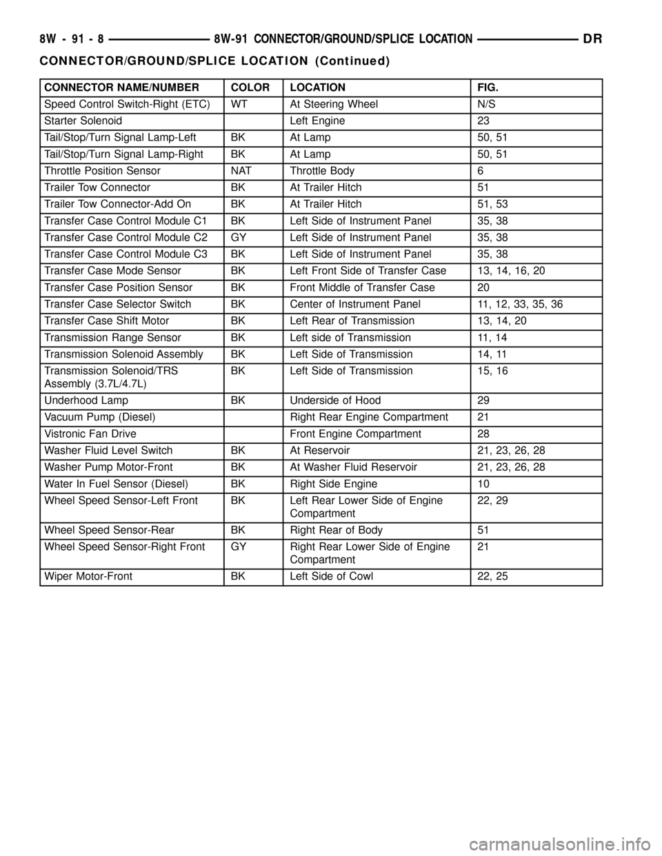
CONNECTOR NAME/NUMBER COLOR LOCATION FIG.
Speed Control Switch-Right (ETC) WT At Steering Wheel N/S
Starter Solenoid Left Engine 23
Tail/Stop/Turn Signal Lamp-Left BK At Lamp 50, 51
Tail/Stop/Turn Signal Lamp-Right BK At Lamp 50, 51
Throttle Position Sensor NAT Throttle Body 6
Trailer Tow Connector BK At Trailer Hitch 51
Trailer Tow Connector-Add On BK At Trailer Hitch 51, 53
Transfer Case Control Module C1 BK Left Side of Instrument Panel 35, 38
Transfer Case Control Module C2 GY Left Side of Instrument Panel 35, 38
Transfer Case Control Module C3 BK Left Side of Instrument Panel 35, 38
Transfer Case Mode Sensor BK Left Front Side of Transfer Case 13, 14, 16, 20
Transfer Case Position Sensor BK Front Middle of Transfer Case 20
Transfer Case Selector Switch BK Center of Instrument Panel 11, 12, 33, 35, 36
Transfer Case Shift Motor BK Left Rear of Transmission 13, 14, 20
Transmission Range Sensor BK Left side of Transmission 11, 14
Transmission Solenoid Assembly BK Left Side of Transmission 14, 11
Transmission Solenoid/TRS
Assembly (3.7L/4.7L)BK Left Side of Transmission 15, 16
Underhood Lamp BK Underside of Hood 29
Vacuum Pump (Diesel) Right Rear Engine Compartment 21
Vistronic Fan Drive Front Engine Compartment 28
Washer Fluid Level Switch BK At Reservoir 21, 23, 26, 28
Washer Pump Motor-Front BK At Washer Fluid Reservoir 21, 23, 26, 28
Water In Fuel Sensor (Diesel) BK Right Side Engine 10
Wheel Speed Sensor-Left Front BK Left Rear Lower Side of Engine
Compartment22, 29
Wheel Speed Sensor-Rear BK Right Rear of Body 51
Wheel Speed Sensor-Right Front GY Right Rear Lower Side of Engine
Compartment21
Wiper Motor-Front BK Left Side of Cowl 22, 25
8W - 91 - 8 8W-91 CONNECTOR/GROUND/SPLICE LOCATIONDR
CONNECTOR/GROUND/SPLICE LOCATION (Continued)
Page 1221 of 2627
requires the use of a DRB IIItscan tool and the
proper Body Diagnostic Procedures manual.
Before any testing of the front control module is
attempted, the battery should be fully charged and
all wire harness and ground connections inspected
around the affected areas on the vehicle.
REMOVAL
(1) Disconnect the positive and negative battery
cables from the battery.
(2) Partially remove the integrated power module
from the engine compartment (Refer to 8 - ELECTRI-
CAL/POWER DISTRIBUTION/INTEGRATED
POWER MODULE - REMOVAL).
(3) Remove the front control module retaining
screws.
(4) Using both hands, pull the front control module
straightfrom the integrated power module assembly
to disconnect the 49-way electrical connector and
remove the front control module from the vehicle.
INSTALLATION
(1) Install the front control module on the inte-
grated power module assembly by pushing the
49-way electrical connector straight in.
(2) Install the front control module retaining
screws. Torque the screws to 7 in. lbs.
(3) Install the integrated power module (Refer to 8
- ELECTRICAL/POWER DISTRIBUTION/INTE-
GRATED POWER MODULE - INSTALLATION).
(4) Connect the positive and negative battery
cables.
IOD FUSE
DESCRIPTION
All vehicles are equipped with an Ignition-Off
Draw (IOD) fuse that is disconnected within the Inte-
grated Power Module when the vehicle is shipped
from the factory. Dealer personnel are to reconnect
the IOD fuse in the Integrated Power Module as part
of the preparation procedures performed just prior to
new vehicle delivery.
A laser printed fuse layout map is integral to the
Integrated Power Module cover to ensure proper fuse
identification. The IOD fuse is a 20 ampere mini
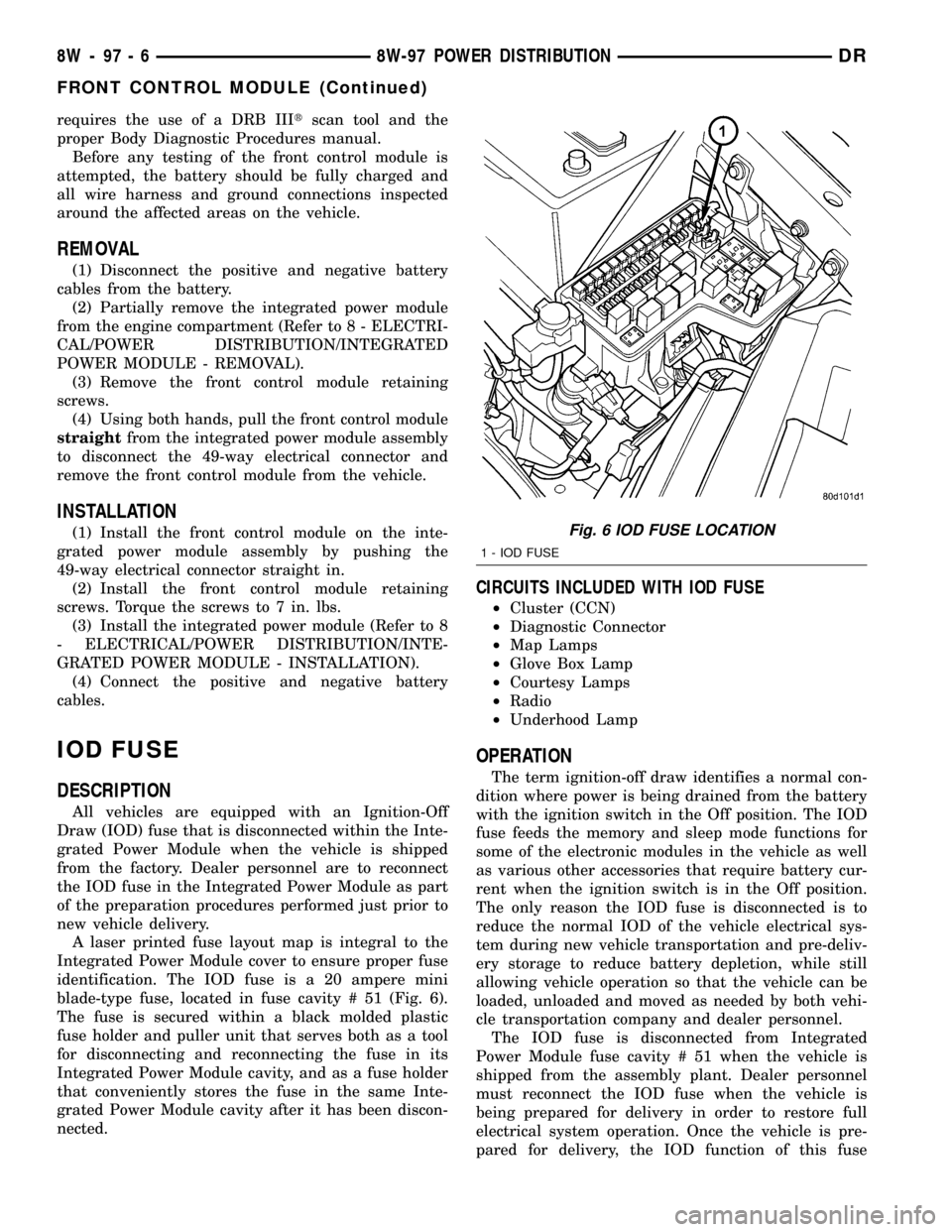
blade-type fuse, located in fuse cavity # 51 (Fig. 6).
The fuse is secured within a black molded plastic
fuse holder and puller unit that serves both as a tool
for disconnecting and reconnecting the fuse in its
Integrated Power Module cavity, and as a fuse holder
that conveniently stores the fuse in the same Inte-
grated Power Module cavity after it has been discon-
nected.
CIRCUITS INCLUDED WITH IOD FUSE
²Cluster (CCN)
²Diagnostic Connector
²Map Lamps
²Glove Box Lamp
²Courtesy Lamps
²Radio
²Underhood Lamp
OPERATION
The term ignition-off draw identifies a normal con-
dition where power is being drained from the battery
with the ignition switch in the Off position. The IOD
fuse feeds the memory and sleep mode functions for
some of the electronic modules in the vehicle as well
as various other accessories that require battery cur-
rent when the ignition switch is in the Off position.
The only reason the IOD fuse is disconnected is to
reduce the normal IOD of the vehicle electrical sys-
tem during new vehicle transportation and pre-deliv-
ery storage to reduce battery depletion, while still
allowing vehicle operation so that the vehicle can be
loaded, unloaded and moved as needed by both vehi-
cle transportation company and dealer personnel.
The IOD fuse is disconnected from Integrated
Power Module fuse cavity # 51 when the vehicle is
shipped from the assembly plant. Dealer personnel
must reconnect the IOD fuse when the vehicle is
being prepared for delivery in order to restore full
electrical system operation. Once the vehicle is pre-
pared for delivery, the IOD function of this fuse
Fig. 6 IOD FUSE LOCATION
1 - IOD FUSE
8W - 97 - 6 8W-97 POWER DISTRIBUTIONDR
FRONT CONTROL MODULE (Continued)
Page 2296 of 2627
BODY
TABLE OF CONTENTS
page page
BODY
WARNING
SAFETY PRECAUTIONS AND WARNINGS . . . 1
DIAGNOSIS AND TESTING
DIAGNOSIS AND TESTING - WATER LEAKS . 1
DIAGNOSIS AND TESTING - WIND NOISE . . . 2
STANDARD PROCEDURE
STANDARD PROCEDURE - BODY
LUBRICATION.........................3
STANDARD PROCEDURE - HEAT STAKING . . 3
STANDARD PROCEDURE - PLASTIC BODY
PANEL REPAIR........................3
STANDARD PROCEDURE - BUZZ, SQUEAK
& RATTLE...........................11
SPECIFICATIONS - TORQUE..............12SPECIAL TOOLS
BODY..............................14
TAILGATE..............................15
DOOR - FRONT.........................18
DOORS - REAR.........................28
EXTERIOR.............................36
HOOD.................................46
INSTRUMENT PANEL.....................49
INTERIOR..............................62
PAINT.................................73
SEATS................................75
STATIONARY GLASS.....................86
WEATHERSTRIP/SEALS...................91
BODY STRUCTURE......................95
BODY
WARNING
SAFETY PRECAUTIONS AND WARNINGS
WARNING: USE AN OSHA APPROVED BREATHING
FILTER WHEN SPRAYING PAINT OR SOLVENTS IN
A CONFINED AREA. PERSONAL INJURY CAN
RESULT.
²AVOID PROLONGED SKIN CONTACT WITH
PETROLEUM OR ALCOHOL ± BASED CLEANING
SOLVENTS. PERSONAL INJURY CAN RESULT.
²DO NOT STAND UNDER A HOISTED VEHICLE
THAT IS NOT PROPERLY SUPPORTED ON SAFETY
STANDS. PERSONAL INJURY CAN RESULT.
CAUTION: When holes must be drilled or punched
in an inner body panel, verify depth of space to the
outer body panel, electrical wiring, or other compo-
nents. Damage to vehicle can result.
²Do not weld exterior panels unless combustible
material on the interior of vehicle is removed from
the repair area. Fire or hazardous conditions, can
result.
²Always have a fire extinguisher ready for use
when welding.
²Disconnect the negative (-) cable clamp from
the battery when servicing electrical components
that are live when the ignition is OFF. Damage to
electrical system can result.²Do not use abrasive chemicals or compounds
on painted surfaces. Damage to finish can result.
²Do not use harsh alkaline based cleaning sol-
vents on painted or upholstered surfaces. Damage
to finish or color can result.
²Do not hammer or pound on plastic trim panel
when servicing interior trim. Plastic panels can
break.
DIAGNOSIS AND TESTING
DIAGNOSIS AND TESTING - WATER LEAKS
Water leaks can be caused by poor sealing,
improper body component alignment, body seam
porosity, missing plugs, or blocked drain holes. Cen-
trifugal and gravitational force can cause water to
drip from a location away from the actual leak point,
making leak detection difficult. All body sealing
points should be water tight in normal wet-driving
conditions. Water flowing downward from the front of
the vehicle should not enter the passenger or luggage
compartment. Moving sealing surfaces will not
always seal water tight under all conditions. At
times, side glass or door seals will allow water to
enter the passenger compartment during high pres-
sure washing or hard driving rain (severe) condi-
tions. Overcompensating on door or glass
adjustments to stop a water leak that occurs under
severe conditions can cause premature seal wear and
excessive closing or latching effort. After completing
a repair, water test vehicle to verify leak has stopped
before returning vehicle to use.
DRBODY 23 - 1
Page 2307 of 2627
SPECIFICATIONS - TORQUE
TORQUE SPECIFICATIONS
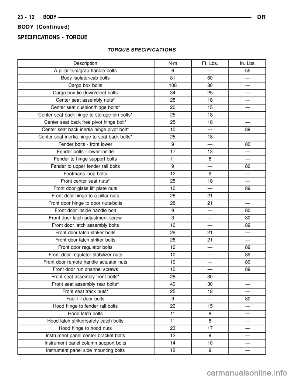
Description N´m Ft. Lbs. In. Lbs.
A-pillar trim/grab handle bolts 6 Ð 55
Body Isolator/cab bolts 81 60 Ð
Cargo box bolts 108 80 Ð
Cargo box tie down/cleat bolts 34 25 Ð
Center seat assembly nuts*25 18 Ð
Center seat cushion/hinge bolts*20 15 Ð
Center seat back hinge to storage bin bolts*25 18 Ð
Center seat back free pivot hinge bolt*25 18 Ð
Center seat back inertia hinge pivot bolt*10 Ð 89
Center seat inertia hinge to seat back bolts*25 18 Ð
Fender bolts - front lower 9 Ð 80
Fender bolts - lower inside 17 13 Ð
Fender to hinge support bolts 11 8 Ð
Fender to upper fender rail bolts 9 Ð 80
Footmans loop bolts 12 9 Ð
Front center seat nuts*25 18 Ð
Front door glass lift plate nuts 10 Ð 89
Front door hinge to a-pillar nuts 28 21 Ð
Front door hinge to door nuts/bolts 28 21 Ð
Front door inside handle bolt 9 Ð 80
Front door latch adjustment screw 3 Ð 30
Front door latch assembly bolts 10 Ð 89
Front door latch striker bolts 28 21 Ð
Front door latch striker bolts 28 21 Ð
Front door regulator bolts 10 Ð 89
Front door regulator stabilizer nuts 10 Ð 89
Front door remote handle actuator nuts 10 Ð 89
Front door run channel screws 10 Ð 89
Front seat assembly front bolts*28 30 Ð
Front seat assembly rear bolts*40 30 Ð
Front seat track nuts*25 18 Ð
Fuel fill door bolts 9 Ð 80
Hood hinge to fender rail bolts 20 15 Ð
Hood latch bolts 11 8 Ð
Hood latch striker/safety catch bolts 11 8 Ð
Hood hinge to hood nuts 23 17 Ð
Instrument panel center bracket bolts 12 9 Ð
Instrument panel column support bolts 14 10 Ð
Instrument panel side mounting bolts 12 9 Ð
23 - 12 BODYDR
BODY (Continued)
Page 2333 of 2627
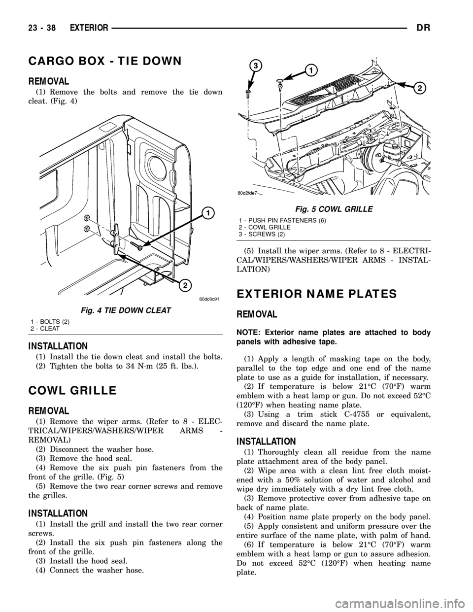
CARGO BOX - TIE DOWN
REMOVAL
(1) Remove the bolts and remove the tie down
cleat. (Fig. 4)
INSTALLATION
(1) Install the tie down cleat and install the bolts.
(2) Tighten the bolts to 34 N´m (25 ft. lbs.).
COWL GRILLE
REMOVAL
(1) Remove the wiper arms. (Refer to 8 - ELEC-
TRICAL/WIPERS/WASHERS/WIPER ARMS -
REMOVAL)
(2) Disconnect the washer hose.
(3) Remove the hood seal.
(4) Remove the six push pin fasteners from the
front of the grille. (Fig. 5)
(5) Remove the two rear corner screws and remove
the grilles.
INSTALLATION
(1) Install the grill and install the two rear corner
screws.
(2) Install the six push pin fasteners along the
front of the grille.
(3) Install the hood seal.
(4) Connect the washer hose.(5) Install the wiper arms. (Refer to 8 - ELECTRI-
CAL/WIPERS/WASHERS/WIPER ARMS - INSTAL-
LATION)
EXTERIOR NAME PLATES
REMOVAL
NOTE: Exterior name plates are attached to body
panels with adhesive tape.
(1) Apply a length of masking tape on the body,
parallel to the top edge and one end of the name
plate to use as a guide for installation, if necessary.
(2) If temperature is below 21ÉC (70ÉF) warm
emblem with a heat lamp or gun. Do not exceed 52ÉC
(120ÉF) when heating name plate.
(3) Using a trim stick C-4755 or equivalent,
remove and discard the name plate.
INSTALLATION
(1) Thoroughly clean all residue from the name
plate attachment area of the body panel.
(2) Wipe area with a clean lint free cloth moist-
ened with a 50% solution of water and alcohol and
wipe dry immediately with a dry lint free cloth.
(3) Remove protective cover from adhesive tape on
back of name plate.
(4)
Position name plate properly on the body panel.
(5) Apply consistent and uniform pressure over the
entire surface of the name plate, with palm of hand.
(6) If temperature is below 21ÉC (70ÉF) warm
emblem with a heat lamp or gun to assure adhesion.
Do not exceed 52ÉC (120ÉF) when heating name
plate.
Fig. 4 TIE DOWN CLEAT
1 - BOLTS (2)
2 - CLEAT
Fig. 5 COWL GRILLE
1 - PUSH PIN FASTENERS (6)
2 - COWL GRILLE
3 - SCREWS (2)
23 - 38 EXTERIORDR
Page 2334 of 2627
FRONT FENDER
REMOVAL
(1) Remove the antenna, if equipped. (Refer to 8 -
ELECTRICAL/AUDIO/ANTENNA BODY & CABLE -
REMOVAL)
(2) Remove the battery tray, if required. (Refer to 8
- ELECTRICAL/BATTERY SYSTEM/TRAY -
REMOVAL)
(3) Remove the cowl grille. (Refer to 23 - BODY/
EXTERIOR/COWL GRILLE - REMOVAL)
(4) Remove the headlamp unit. (Refer to 8 - ELEC-
TRICAL/LAMPS/LIGHTING - EXTERIOR/HEAD-
LAMP UNIT - REMOVAL)
(5) Remove the wheelhouse splash shield. (Refer to
23 - BODY/EXTERIOR/FRONT WHEELHOUSE
SPLASH SHIELD - REMOVAL)
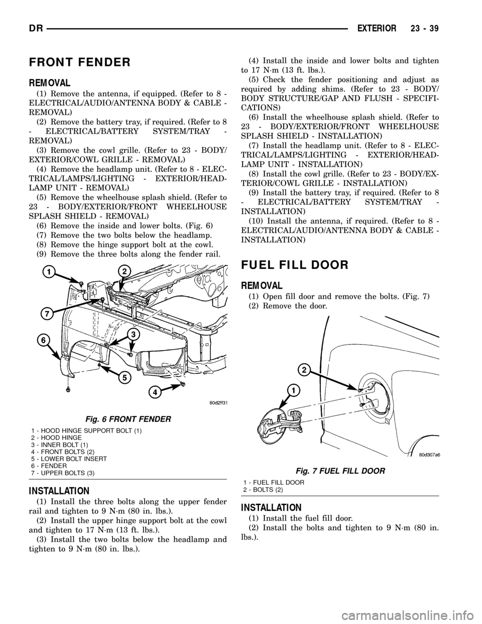
(6) Remove the inside and lower bolts. (Fig. 6)
(7) Remove the two bolts below the headlamp.
(8) Remove the hinge support bolt at the cowl.
(9) Remove the three bolts along the fender rail.
INSTALLATION
(1) Install the three bolts along the upper fender
rail and tighten to 9 N´m (80 in. lbs.).
(2) Install the upper hinge support bolt at the cowl
and tighten to 17 N´m (13 ft. lbs.).
(3) Install the two bolts below the headlamp and
tighten to 9 N´m (80 in. lbs.).(4) Install the inside and lower bolts and tighten
to 17 N´m (13 ft. lbs.).
(5) Check the fender positioning and adjust as
required by adding shims. (Refer to 23 - BODY/
BODY STRUCTURE/GAP AND FLUSH - SPECIFI-
CATIONS)
(6) Install the wheelhouse splash shield. (Refer to
23 - BODY/EXTERIOR/FRONT WHEELHOUSE
SPLASH SHIELD - INSTALLATION)
(7) Install the headlamp unit. (Refer to 8 - ELEC-
TRICAL/LAMPS/LIGHTING - EXTERIOR/HEAD-
LAMP UNIT - INSTALLATION)
(8) Install the cowl grille. (Refer to 23 - BODY/EX-
TERIOR/COWL GRILLE - INSTALLATION)
(9) Install the battery tray, if required. (Refer to 8
- ELECTRICAL/BATTERY SYSTEM/TRAY -
INSTALLATION)
(10) Install the antenna, if required. (Refer to 8 -
ELECTRICAL/AUDIO/ANTENNA BODY & CABLE -
INSTALLATION)
FUEL FILL DOOR
REMOVAL
(1) Open fill door and remove the bolts. (Fig. 7)
(2) Remove the door.
INSTALLATION
(1) Install the fuel fill door.
(2) Install the bolts and tighten to 9 N´m (80 in.
lbs.).
Fig. 6 FRONT FENDER
1 - HOOD HINGE SUPPORT BOLT (1)
2 - HOOD HINGE
3 - INNER BOLT (1)
4 - FRONT BOLTS (2)
5 - LOWER BOLT INSERT
6 - FENDER
7 - UPPER BOLTS (3)
Fig. 7 FUEL FILL DOOR
1 - FUEL FILL DOOR
2 - BOLTS (2)
DREXTERIOR 23 - 39
Page 2337 of 2627
INSTALLATION
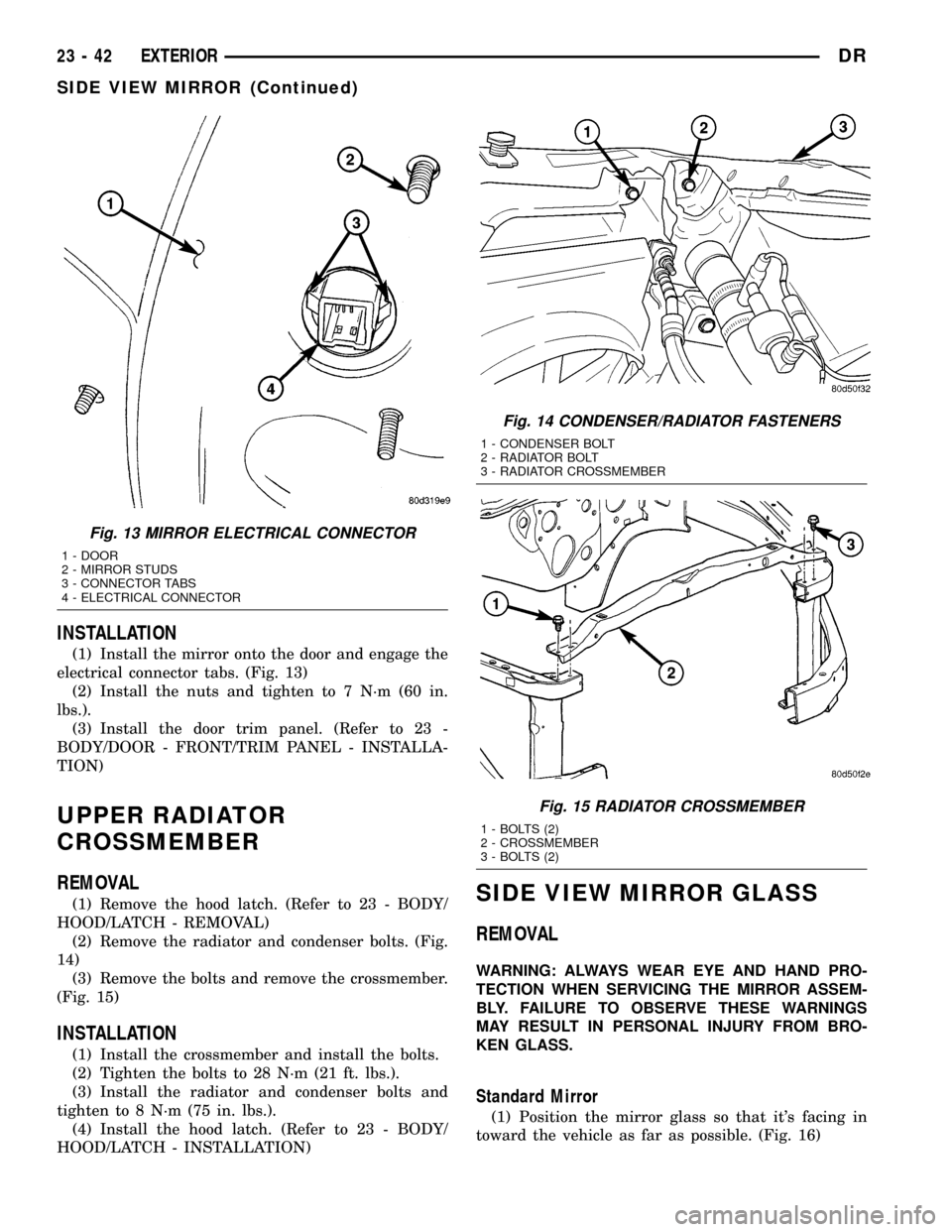
(1) Install the mirror onto the door and engage the
electrical connector tabs. (Fig. 13)
(2) Install the nuts and tighten to 7 N´m (60 in.
lbs.).
(3) Install the door trim panel. (Refer to 23 -
BODY/DOOR - FRONT/TRIM PANEL - INSTALLA-
TION)
UPPER RADIATOR
CROSSMEMBER
REMOVAL
(1) Remove the hood latch. (Refer to 23 - BODY/
HOOD/LATCH - REMOVAL)
(2) Remove the radiator and condenser bolts. (Fig.
14)
(3) Remove the bolts and remove the crossmember.
(Fig. 15)
INSTALLATION
(1) Install the crossmember and install the bolts.
(2) Tighten the bolts to 28 N´m (21 ft. lbs.).
(3) Install the radiator and condenser bolts and
tighten to 8 N´m (75 in. lbs.).
(4) Install the hood latch. (Refer to 23 - BODY/
HOOD/LATCH - INSTALLATION)
SIDE VIEW MIRROR GLASS
REMOVAL
WARNING: ALWAYS WEAR EYE AND HAND PRO-
TECTION WHEN SERVICING THE MIRROR ASSEM-
BLY. FAILURE TO OBSERVE THESE WARNINGS
MAY RESULT IN PERSONAL INJURY FROM BRO-
KEN GLASS.
Standard Mirror
(1) Position the mirror glass so that it's facing in
toward the vehicle as far as possible. (Fig. 16)
Fig. 13 MIRROR ELECTRICAL CONNECTOR
1 - DOOR
2 - MIRROR STUDS
3 - CONNECTOR TABS
4 - ELECTRICAL CONNECTOR
Fig. 14 CONDENSER/RADIATOR FASTENERS
1 - CONDENSER BOLT
2 - RADIATOR BOLT
3 - RADIATOR CROSSMEMBER
Fig. 15 RADIATOR CROSSMEMBER
1 - BOLTS (2)
2 - CROSSMEMBER
3 - BOLTS (2)
23 - 42 EXTERIORDR
SIDE VIEW MIRROR (Continued)
Page 2341 of 2627
HOOD
TABLE OF CONTENTS
page page
HINGE
REMOVAL.............................46
INSTALLATION.........................46
HOOD
REMOVAL.............................46
INSTALLATION.........................47
LATCH
REMOVAL.............................47
INSTALLATION.........................47LATCH RELEASE CABLE/HANDLE ASSEMBLY
REMOVAL.............................47
INSTALLATION.........................47
LATCH STRIKER / SECONDARY CATCH
REMOVAL.............................47
INSTALLATION.........................48
SUPPORT CYLINDER
REMOVAL.............................48
INSTALLATION.........................48
HINGE
REMOVAL
NOTE: It is not necessary to remove the hood to
replace one or both hinges. The hinges can be
replaced one at a time.
(1) Remove the cowl grille. (Refer to 23 - BODY/
EXTERIOR/COWL GRILLE - REMOVAL)
(2) Using a grease pencil or equivalent, mark the
position of the hinge on the hood.
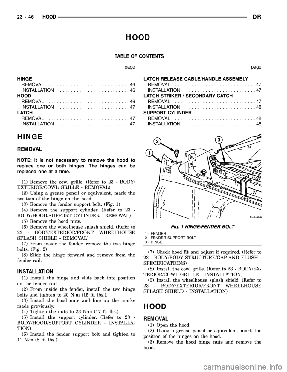
(3) Remove the fender support bolt. (Fig. 1)
(4) Remove the support cylinder. (Refer to 23 -
BODY/HOOD/SUPPORT CYLINDER - REMOVAL)
(5) Remove the hood nuts.
(6) Remove the wheelhouse splash shield. (Refer to
23 - BODY/EXTERIOR/FRONT WHEELHOUSE
SPLASH SHIELD - REMOVAL)
(7) From inside the fender, remove the two hinge
bolts. (Fig. 2)
(8) Slide the hinge forward and remove from the
fender rail.
INSTALLATION
(1) Install the hinge and slide back into position
on the fender rail.
(2) From inside the fender, install the two hinge
bolts and tighten to 20 N´m (15 ft. lbs.).
(3) Install the hood nuts and line up the marks
made previously.
(4) Tighten the nuts to 23 N´m (17 ft. lbs.).
(5) Install the support cylinder. (Refer to 23 -
BODY/HOOD/SUPPORT CYLINDER - INSTALLA-
TION)
(6) Install the fender support bolt and tighten to
11 N´m (8 ft. lbs.).(7) Check hood fit and adjust if required. (Refer to
23 - BODY/BODY STRUCTURE/GAP AND FLUSH -
SPECIFICATIONS)
(8) Install the cowl grille. (Refer to 23 - BODY/EX-
TERIOR/COWL GRILLE - INSTALLATION)
(9) Install the wheelhouse splash shield. (Refer to
23 - BODY/EXTERIOR/FRONT WHEELHOUSE
SPLASH SHIELD - INSTALLATION)
HOOD
REMOVAL
(1) Open the hood.
(2) Using a grease pencil or equivalent, mark the
position of the hinges on the hood.
(3) Remove the hood hinge nuts and remove the
hood.
Fig. 1 HINGE/FENDER BOLT
1 - FENDER
2 - FENDER SUPPORT BOLT
3 - HINGE
23 - 46 HOODDR