1998 DODGE RAM 1500 Backup
[x] Cancel search: BackupPage 1123 of 2627
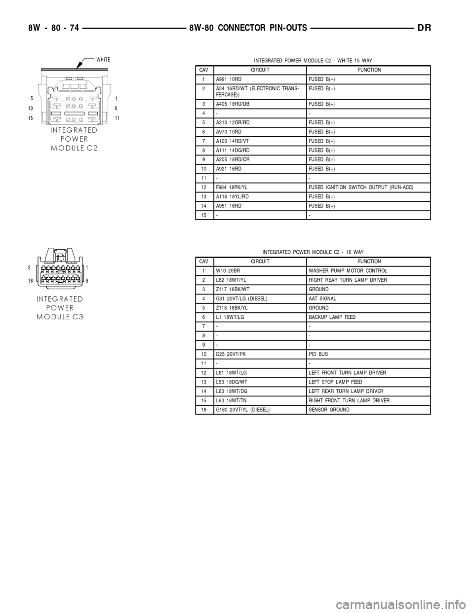
INTEGRATED POWER MODULE C2 - WHITE 15 WAY
CAV CIRCUIT FUNCTION
1 A991 10RD FUSED B(+)
2 A34 16RD/WT (ELECTRONIC TRANS-
FERCASE))FUSED B(+)
3 A405 18RD/DB FUSED B(+)
4- -
5 A210 12OR/RD FUSED B(+)
6 A970 10RD FUSED B(+)
7 A100 14RD/VT FUSED B(+)
8 A111 14DG/RD FUSED B(+)
9 A205 18RD/OR FUSED B(+)
10 A921 16RD FUSED B(+)
11 - -
12 F984 18PK/YL FUSED IGNITION SWITCH OUTPUT (RUN-ACC)
13 A116 18YL/RD FUSED B(+)
14 A951 16RD FUSED B(+)
15 - -
INTEGRATED POWER MODULE C3 - 16 WAY
CAV CIRCUIT FUNCTION
1 W10 20BR WASHER PUMP MOTOR CONTROL
2 L62 18WT/YL RIGHT REAR TURN LAMP DRIVER
3 Z117 18BK/WT GROUND
4 G31 20VT/LG (DIESEL) AAT SIGNAL
5 Z118 18BK/YL GROUND
6 L1 18WT/LG BACKUP LAMP FEED
7- -
8- -
9- -
10 D25 20VT/PK PCI BUS
11 - -
12 L61 18WT/LG LEFT FRONT TURN LAMP DRIVER
13 L53 18DG/WT LEFT STOP LAMP FEED
14 L63 18WT/DG LEFT REAR TURN LAMP DRIVER
15 L60 18WT/TN RIGHT FRONT TURN LAMP DRIVER
16 G180 20VT/YL (DIESEL) SENSOR GROUND
8W - 80 - 74 8W-80 CONNECTOR PIN-OUTSDR
Page 1147 of 2627
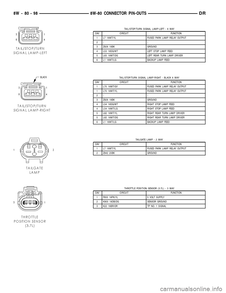
TAIL/STOP/TURN SIGNAL LAMP-LEFT-6WAY
CAV CIRCUIT FUNCTION
1 L7 18WT/YL FUSED PARK LAMP RELAY OUTPUT
2- -
3 Z928 18BK GROUND
4 L53 18DG/WT LEFT STOP LAMP FEED
5 L63 18WT/DG LEFT REAR TURN LAMP DRIVER
6 L1 18WT/LG BACKUP LAMP FEED
TAIL/STOP/TURN SIGNAL LAMP-RIGHT - BLACK 6 WAY
CAV CIRCUIT FUNCTION
1 L70 18WT/GY FUSED PARK LAMP RELAY OUTPUT
1 L70 18WT/YL FUSED PARK LAMP RELAY OUTPUT
2- -
3 Z928 18BK GROUND
4 L54 18DG/WT RIGHT STOP LAMP FEED
4 L54 18WT/LG RIGHT STOP LAMP FEED
5 L62 18WT/YL RIGHT REAR TURN LAMP DRIVER
5 L62 18WT/DG RIGHT REAR TURN LAMP DRIVER
6 L1 18WT/LG BACKUP LAMP FEED
TAILGATE LAMP-2WAY
CAV CIRCUIT FUNCTION
1 L7 18WT/YL FUSED PARK LAMP RELAY OUTPUT
2 Z942 20BK GROUND
THROTTLE POSITION SENSOR (3.7L)-3WAY
CAV CIRCUIT FUNCTION
1 F855 18PK/YL 5 VOLT SUPPLY
2 K900 18DB/DG SENSOR GROUND
3 K22 18BR/OR TP NO. 1 SIGNAL
8W - 80 - 98 8W-80 CONNECTOR PIN-OUTSDR
Page 1148 of 2627
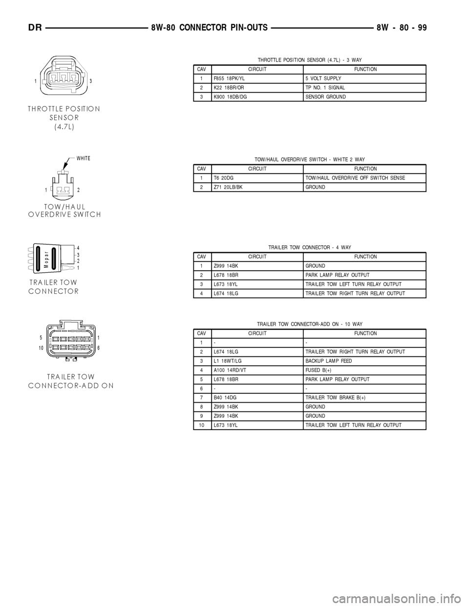
THROTTLE POSITION SENSOR (4.7L)-3WAY
CAV CIRCUIT FUNCTION
1 F855 18PK/YL 5 VOLT SUPPLY
2 K22 18BR/OR TP NO. 1 SIGNAL
3 K900 18DB/DG SENSOR GROUND
TOW/HAUL OVERDRIVE SWITCH - WHITE 2 WAY
CAV CIRCUIT FUNCTION
1 T6 20DG TOW/HAUL OVERDRIVE OFF SWITCH SENSE
2 Z71 20LB/BK GROUND
TRAILER TOW CONNECTOR-4WAY
CAV CIRCUIT FUNCTION
1 Z999 14BK GROUND
2 L678 18BR PARK LAMP RELAY OUTPUT
3 L673 18YL TRAILER TOW LEFT TURN RELAY OUTPUT
4 L674 18LG TRAILER TOW RIGHT TURN RELAY OUTPUT
TRAILER TOW CONNECTOR-ADD ON - 10 WAY
CAV CIRCUIT FUNCTION
1- -
2 L674 18LG TRAILER TOW RIGHT TURN RELAY OUTPUT
3 L1 18WT/LG BACKUP LAMP FEED
4 A100 14RD/VT FUSED B(+)
5 L678 18BR PARK LAMP RELAY OUTPUT
6- -
7 B40 14DG TRAILER TOW BRAKE B(+)
8 Z999 14BK GROUND
9 Z999 14BK GROUND
10 L673 18YL TRAILER TOW LEFT TURN RELAY OUTPUT
DR8W-80 CONNECTOR PIN-OUTS 8W - 80 - 99
Page 1151 of 2627
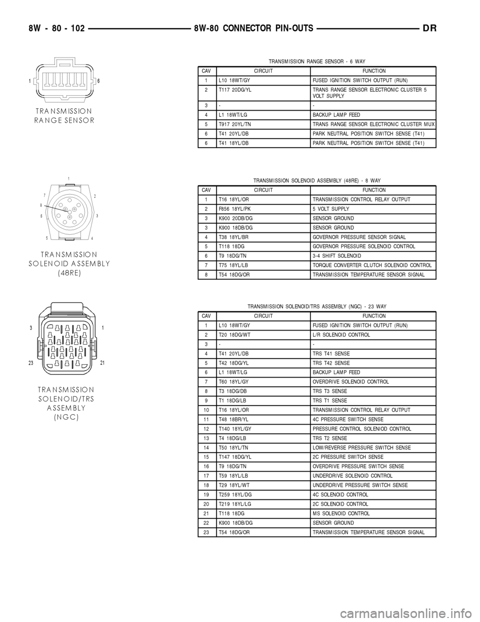
TRANSMISSION RANGE SENSOR-6WAY
CAV CIRCUIT FUNCTION
1 L10 18WT/GY FUSED IGNITION SWITCH OUTPUT (RUN)
2 T117 20DG/YL TRANS RANGE SENSOR ELECTRONIC CLUSTER 5
VOLT SUPPLY
3- -
4 L1 18WT/LG BACKUP LAMP FEED
5 T917 20YL/TN TRANS RANGE SENSOR ELECTRONIC CLUSTER MUX
6 T41 20YL/DB PARK NEUTRAL POSITION SWITCH SENSE (T41)
6 T41 18YL/DB PARK NEUTRAL POSITION SWITCH SENSE (T41)
TRANSMISSION SOLENOID ASSEMBLY (48RE)-8WAY
CAV CIRCUIT FUNCTION
1 T16 18YL/OR TRANSMISSION CONTROL RELAY OUTPUT
2 F856 18YL/PK 5 VOLT SUPPLY
3 K900 20DB/DG SENSOR GROUND
3 K900 18DB/DG SENSOR GROUND
4 T38 18YL/BR GOVERNOR PRESSURE SENSOR SIGNAL
5 T118 18DG GOVERNOR PRESSURE SOLENOID CONTROL
6 T9 18DG/TN 3-4 SHIFT SOLENOID
7 T75 18YL/LB TORQUE CONVERTER CLUTCH SOLENOID CONTROL
8 T54 18DG/OR TRANSMISSION TEMPERATURE SENSOR SIGNAL
TRANSMISSION SOLENOID/TRS ASSEMBLY (NGC) - 23 WAY
CAV CIRCUIT FUNCTION
1 L10 18WT/GY FUSED IGNITION SWITCH OUTPUT (RUN)
2 T20 18DG/WT L/R SOLENOID CONTROL
3- -
4 T41 20YL/DB TRS T41 SENSE
5 T42 18DG/YL TRS T42 SENSE
6 L1 18WT/LG BACKUP LAMP FEED
7 T60 18YL/GY OVERDRIVE SOLENOID CONTROL
8 T3 18DG/DB TRS T3 SENSE
9 T1 18DG/LB TRS T1 SENSE
10 T16 18YL/OR TRANSMISSION CONTROL RELAY OUTPUT
11 T48 18BR/YL 4C PRESSURE SWITCH SENSE
12 T140 18YL/GY PRESSURE CONTROL SOLENIOD CONTROL
13 T4 18DG/LB TRS T2 SENSE
14 T50 18YL/TN LOW/REVERSE PRESSURE SWITCH SENSE
15 T147 18DG/YL 2C PRESSURE SWITCH SENSE
16 T9 18DG/TN OVERDRIVE PRESSURE SWITCH SENSE
17 T59 18YL/LB UNDERDRIVE SOLENOID CONTROL
18 T29 18YL/WT UNDERDRIVE PRESSURE SWITCH SENSE
19 T259 18YL/DG 4C SOLENOID CONTROL
20 T219 18YL/LG 2C SOLENOID CONTROL
21 T118 18DG MS SOLENOID CONTROL
22 K900 18DB/DG SENSOR GROUND
23 T54 18DG/OR TRANSMISSION TEMPERATURE SENSOR SIGNAL
8W - 80 - 102 8W-80 CONNECTOR PIN-OUTSDR
Page 1154 of 2627
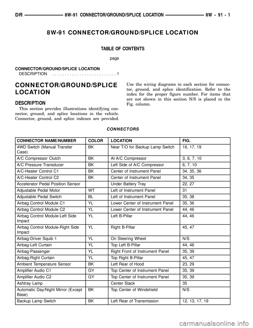
8W-91 CONNECTOR/GROUND/SPLICE LOCATION
TABLE OF CONTENTS
page
CONNECTOR/GROUND/SPLICE LOCATION
DESCRIPTION..........................1
CONNECTOR/GROUND/SPLICE
LOCATION
DESCRIPTION
This section provides illustrations identifying con-
nector, ground, and splice locations in the vehicle.
Connector, ground, and splice indexes are provided.Use the wiring diagrams in each section for connec-
tor, ground, and splice identification. Refer to the
index for the proper figure number. For items that
are not shown in this section N/S is placed in the
Fig. column.
CONNECTORS
CONNECTOR NAME/NUMBER COLOR LOCATION FIG.
4WD Switch (Manual Transfer
Case)BK Near T/O for Backup Lamp Switch 16, 17, 19
A/C Compressor Clutch BK At A/C Compressor 3, 6, 7, 10
A/C Pressure Transducer BK Left Side of A/C Compressor 6, 7, 10
A/C-Heater Control C1 BK Center of Instrument Panel 34, 35, 36
A/C-Heater Control C2 BK Center of Instrument Panel 34, 35
Accelerator Pedal Position Sensor Under Battery Tray 22, 27
Adjustable Pedal Motor WT Left of Instrument Panel 31
Adjustable Pedal Switch BL Left of Instrument Panel 35, 38
Airbag Control Module C1 YL Lower Center of Instrument Panel 35, 36
Airbag Control Module C2 YL Lower Center of Instrument Panel 44, 46
Airbag Control Module-Left Side
ImpactYL Left B-Pillar 44, 46
Airbag Control Module-Right Side
ImpactYL Right B-Pillar 45, 47
Airbag-Driver Squib 1 YL On Steering Wheel N/S
Airbag-Left Curtain YL Top Left B-Pillar 44, 46
Airbag-Passenger YL Right Front of Instrument Panel 35, 39
Airbag-Right Curtain YL Top Right B-Pillar 45, 47
Ambient Temperature Sensor BK Left Rear of Hood 23, 29
Amplifier Audio C1 GY Top Center of Instrument Panel 35, 39
Amplifier Audio C2 GY Top Center of Instrument Panel 35, 39
Ashtray Lamp Center Stack 35
Automatic Day/Night Mirror (Except
Base)BK Top Center of Windshield N/S
Backup Lamp Switch BK Left Rear of Transmission 12, 13, 17, 19
DR8W-91 CONNECTOR/GROUND/SPLICE LOCATION 8W - 91 - 1
Page 1640 of 2627

INSTALLATION
Engine Mounted Sensor :
The APPS is serviced (replaced) as one assembly
including the lever, brackets and sensor. The APPS is
calibrated to its mounting bracket.
(1) Snap electrical connector into bottom of sensor.
(2) Position APPS assembly to engine and install 6
bolts. Tighten bolts to 24 N´m (18 ft. lbs.) torque.
(3) Connect wiring harness clip at bottom of
bracket.
(4) Refer to Group 21, Transmission for transmis-
sion control cable installation procedures.
(5) Install speed control cable into mounting
bracket. Be sure pinch tabs have secured cable.
(6) Install throttle cable into mounting bracket. Be
sure pinch tabs have secured cable.
(7) Connect throttle cable at lever (snaps on).
(8) Connect speed control cable to lever by pushing
cable connector rearward onto lever pin while hold-
ing lever forward.
(9) Install cable cover.
(10) Connect both negative battery cables to both
batteries.
(11) If necessary, use DRB IIItScan Tool to erase
any Diagnostic Trouble Codes (DTC's) from ECM.Battery Tray Mounted Sensor :
(1) Install Accelerator Pedal Position Sensor
(APPS) cable to accelerator pedal. Refer to Accelera-
tor Pedal Removal / Installation.
(2) Connect electrical connector to APPS.
(3) If necessary, connect cable to APPS lever ball
socket (snaps on).
(4) Snap APPS cable cover closed.
(5) Position APPS assembly to bottom of battery
tray and install 3 bolts. Refer to Torque Specifica-
tions.
(6) Install wheelhouse liner. Refer to Body.
(7) Perform the following procedure:
(a) Connect negative battery cables to both bat-
teries.
(b) Turn key switch ON, but do not crank
engine.
(c) Leave key switch ON for a minimum of 10
seconds. This will allow ECM to learn electrical
parameters.
(8) If necessary, use DRB IIItScan Tool to erase
any Diagnostic Trouble Codes (DTC's) from ECM.
CAMSHAFT POSITION
SENSOR
DESCRIPTION
The Camshaft Position Sensor (CMP) on the 5.9L
diesel engine is located below the fuel injection
pump. It is bolted to the back of the timing gear
housing.
OPERATION
The diesel Camshaft Position Sensor (CMP) con-
tains a hall effect device. A rotating target wheel
(tonewheel) for the CMP is located on the camshaft
gear. This hall effect device detects notches located
on the back side of the camshaft gear. As the cam-
shaft gear rotates, the notches pass the tip of the
CMP.
When the leading edge of the notch passes the tip
of the CMP, the following occurs: The interruption of
magnetic field causes the voltage to switch high
resulting in a signal of approximately 5 volts.
When the trailing edge of the notch passes the tip
of the CMP, the following occurs: The change of the
magnetic field causes the signal voltage to switch low
to 0 volts.
The CMP (Fig. 8) provides a signal to the Engine
Control Module (ECM) at all times when the engine
is running. The ECM uses the CMP information pri-
marily on engine start-up. Once the engine is run-
ning, the ECM uses the CMP as a backup sensor for
engine speed. The Crankshaft Position Sensor (CKP)
Fig. 7 APPS CABLE (OFF ENGINE MOUNTING)
1 - APPS LEVER
2 - BALL SOCKET
3 - SWING-DOWN DOOR
4 - CABLE CLIP
5 - CABLE
DRFUEL INJECTION - DIESEL 14 - 71
ACCELERATOR PEDAL POSITION SENSOR (Continued)
Page 1642 of 2627

When the leading edge of the tonewheel notch
passes the tip of the CKP, the following occurs: The
interruption of magnetic field causes the voltage to
switch high resulting in a signal of approximately 5
volts.
When the trailing edge of the tonewheel notch
passes the tip of the CKP, the following occurs: The
change of the magnetic field causes the signal voltage
to switch low to 0 volts.
The Camshaft Position Sensor (CMP) also provides
a signal to the Engine Control Module (ECM) at all
times when the engine is running. The ECM uses
this CMP information primarily on engine start-up.
Once the engine is running, the ECM uses the CMP
as a backup sensor for engine speed.
REMOVAL
(1) Raise and support vehicle
(2) Disconnect electrical connector at CKP sensor
(Fig. 12).
(3) Remove 1 sensor mounting bolt.
(4) Remove CKP sensor.
INSTALLATION
(1) Position and install CKP sensor to engine.
(2) Install 1 sensor mounting bolt and tighten to 9
N´m (80 in. lbs.) torque.(3) Install electrical connector to CKP sensor (Fig.
12).
Fig. 10 5.9L DIESEL CKP
1 - ENGINE HARMONIC BALANCER
2 - FRONT OF TIMING GEAR COVER
3 - CKP MOUNTING BOLT
4 - ELEC. CONNECTOR
5 - CKP SENSOR
6 - NOTCHES
Fig. 11 CKP NOTCHED TONEWHEEL
1 - ENGINE HARMONIC BALANCER
2 - NOTCHED TONEWHEEL
3 - FRONT OF CRANKSHAFT
Fig. 12 5.9L DIESEL CKP
1 - ENGINE HARMONIC BALANCER
2 - FRONT OF TIMING GEAR COVER
3 - CKP MOUNTING BOLT
4 - ELEC. CONNECTOR
5 - CKP SENSOR
6 - NOTCHES
DRFUEL INJECTION - DIESEL 14 - 73
CRANKSHAFT POSITION SENSOR (Continued)
Page 1681 of 2627

NOTE: Tighten the slide hammer adapter 8990 into
the seal using wrenches, in order to make a tight fit
to pull the seal out. If this is not performed the seal
may tear on the removal making it difficult to
remove.
(12) Remove oil seal from the housing with a spe-
cial tool 8990 with slide hammer C-3752. (Fig. 5).
INSTALLATION
INSTALLATION - GAS ENGINE
NOTE: Generous amounts of the high temperature
grease from the seal kit should be applied to areas
between the pitman shaft bearing and oil seals and
also between the dust seals and snap ring.
(1) Coat the oil seal and washer withhigh temp
grease.
NOTE: Install the oil seal with the lip facing inward.
Flat side of the oil seal should be against the
washer.
(2) Install the oil seal with special tool 8989 driver
and C-4171 handle (Fig. 7).
(3) Install backup washer.
(4) Install the retainer ring with snap ring pliers.
(5) Coat the dust seal withhigh temp grease.
(6) Install the dust seal with a driver and handle
(Fig. 7).
(7) Install protective seal protector 8993 over the
shaft (Fig. 8).(8) Install the pitman shaft into the steering gear
until it fully seats into the bearing.
(9) Install the new cover bolts and tighten to 68
N´m (50 ft. lbs.).
(10) Install the pitman arm (Refer to 19 - STEER-
ING/LINKAGE/PITMAN ARM - INSTALLATION).
INSTALLATION - DIESEL
NOTE: Generous amounts of the high temperature
grease from the seal kit should be applied to areas
between the pitman shaft bearing and oil seals and
also between the dust seals and snap ring.
(1) Coat the oil seal and washer withhigh temp
grease.
NOTE: Install the oil seal with the lip facing inward.
Flat side of the oil seal should be against the
washer.
(2) Install the oil seal with special tool 8989 driver
and C-4171 handle (Fig. 7).
(3) Install backup washer.
(4) Install the retainer ring with snap ring pliers.
(5) Coat the dust seal withhigh temp grease.
(6) Install the dust seal with special tool 8989
driver and C-4171 handle (Fig. 7).
(7) Install protective seal protector 8993 over the
shaft (Fig. 8).
(8) Install the pitman shaft into the steering gear
until it fully seats into the bearing.
(9) Install the new cover bolts and tighten to 68
N´m (50 ft. lbs.).
(10) Install the steering gear (Refer to 19 -
STEERING/GEAR - INSTALLATION).
Fig. 7 SEAL INSTALLATION
1 - SPECIAL TOOL C-4171
2 - SPECIAL TOOL 8989
3 - STEERING GEAR
Fig. 8 PITMAN SHAFT SEAL PROTECTOR
1 - STEERING GEAR
2 - SPECIAL TOOL 8993
19 - 26 GEAR - LINK/COILDR
PITMAN SHAFT SEAL (Continued)