1998 DODGE RAM 1500 Over drive
[x] Cancel search: Over drivePage 1151 of 2627
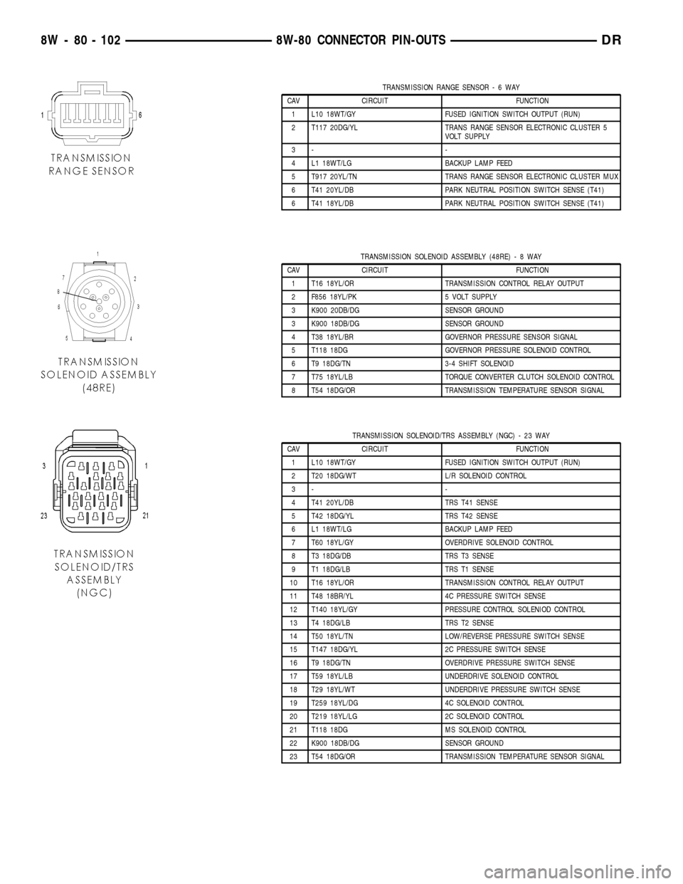
TRANSMISSION RANGE SENSOR-6WAY
CAV CIRCUIT FUNCTION
1 L10 18WT/GY FUSED IGNITION SWITCH OUTPUT (RUN)
2 T117 20DG/YL TRANS RANGE SENSOR ELECTRONIC CLUSTER 5
VOLT SUPPLY
3- -
4 L1 18WT/LG BACKUP LAMP FEED
5 T917 20YL/TN TRANS RANGE SENSOR ELECTRONIC CLUSTER MUX
6 T41 20YL/DB PARK NEUTRAL POSITION SWITCH SENSE (T41)
6 T41 18YL/DB PARK NEUTRAL POSITION SWITCH SENSE (T41)
TRANSMISSION SOLENOID ASSEMBLY (48RE)-8WAY
CAV CIRCUIT FUNCTION
1 T16 18YL/OR TRANSMISSION CONTROL RELAY OUTPUT
2 F856 18YL/PK 5 VOLT SUPPLY
3 K900 20DB/DG SENSOR GROUND
3 K900 18DB/DG SENSOR GROUND
4 T38 18YL/BR GOVERNOR PRESSURE SENSOR SIGNAL
5 T118 18DG GOVERNOR PRESSURE SOLENOID CONTROL
6 T9 18DG/TN 3-4 SHIFT SOLENOID
7 T75 18YL/LB TORQUE CONVERTER CLUTCH SOLENOID CONTROL
8 T54 18DG/OR TRANSMISSION TEMPERATURE SENSOR SIGNAL
TRANSMISSION SOLENOID/TRS ASSEMBLY (NGC) - 23 WAY
CAV CIRCUIT FUNCTION
1 L10 18WT/GY FUSED IGNITION SWITCH OUTPUT (RUN)
2 T20 18DG/WT L/R SOLENOID CONTROL
3- -
4 T41 20YL/DB TRS T41 SENSE
5 T42 18DG/YL TRS T42 SENSE
6 L1 18WT/LG BACKUP LAMP FEED
7 T60 18YL/GY OVERDRIVE SOLENOID CONTROL
8 T3 18DG/DB TRS T3 SENSE
9 T1 18DG/LB TRS T1 SENSE
10 T16 18YL/OR TRANSMISSION CONTROL RELAY OUTPUT
11 T48 18BR/YL 4C PRESSURE SWITCH SENSE
12 T140 18YL/GY PRESSURE CONTROL SOLENIOD CONTROL
13 T4 18DG/LB TRS T2 SENSE
14 T50 18YL/TN LOW/REVERSE PRESSURE SWITCH SENSE
15 T147 18DG/YL 2C PRESSURE SWITCH SENSE
16 T9 18DG/TN OVERDRIVE PRESSURE SWITCH SENSE
17 T59 18YL/LB UNDERDRIVE SOLENOID CONTROL
18 T29 18YL/WT UNDERDRIVE PRESSURE SWITCH SENSE
19 T259 18YL/DG 4C SOLENOID CONTROL
20 T219 18YL/LG 2C SOLENOID CONTROL
21 T118 18DG MS SOLENOID CONTROL
22 K900 18DB/DG SENSOR GROUND
23 T54 18DG/OR TRANSMISSION TEMPERATURE SENSOR SIGNAL
8W - 80 - 102 8W-80 CONNECTOR PIN-OUTSDR
Page 1156 of 2627
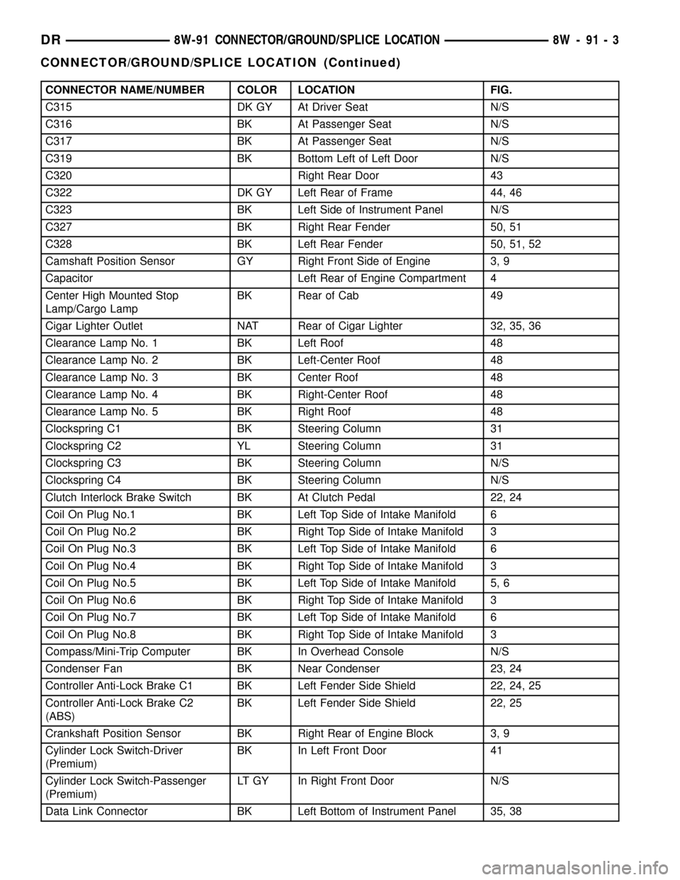
CONNECTOR NAME/NUMBER COLOR LOCATION FIG.
C315 DK GY At Driver Seat N/S
C316 BK At Passenger Seat N/S
C317 BK At Passenger Seat N/S
C319 BK Bottom Left of Left Door N/S
C320 Right Rear Door 43
C322 DK GY Left Rear of Frame 44, 46
C323 BK Left Side of Instrument Panel N/S
C327 BK Right Rear Fender 50, 51
C328 BK Left Rear Fender 50, 51, 52
Camshaft Position Sensor GY Right Front Side of Engine 3, 9
Capacitor Left Rear of Engine Compartment 4
Center High Mounted Stop
Lamp/Cargo LampBK Rear of Cab 49
Cigar Lighter Outlet NAT Rear of Cigar Lighter 32, 35, 36
Clearance Lamp No. 1 BK Left Roof 48
Clearance Lamp No. 2 BK Left-Center Roof 48
Clearance Lamp No. 3 BK Center Roof 48
Clearance Lamp No. 4 BK Right-Center Roof 48
Clearance Lamp No. 5 BK Right Roof 48
Clockspring C1 BK Steering Column 31
Clockspring C2 YL Steering Column 31
Clockspring C3 BK Steering Column N/S
Clockspring C4 BK Steering Column N/S
Clutch Interlock Brake Switch BK At Clutch Pedal 22, 24
Coil On Plug No.1 BK Left Top Side of Intake Manifold 6
Coil On Plug No.2 BK Right Top Side of Intake Manifold 3
Coil On Plug No.3 BK Left Top Side of Intake Manifold 6
Coil On Plug No.4 BK Right Top Side of Intake Manifold 3
Coil On Plug No.5 BK Left Top Side of Intake Manifold 5, 6
Coil On Plug No.6 BK Right Top Side of Intake Manifold 3
Coil On Plug No.7 BK Left Top Side of Intake Manifold 6
Coil On Plug No.8 BK Right Top Side of Intake Manifold 3
Compass/Mini-Trip Computer BK In Overhead Console N/S
Condenser Fan BK Near Condenser 23, 24
Controller Anti-Lock Brake C1 BK Left Fender Side Shield 22, 24, 25
Controller Anti-Lock Brake C2
(ABS)BK Left Fender Side Shield 22, 25
Crankshaft Position Sensor BK Right Rear of Engine Block 3, 9
Cylinder Lock Switch-Driver
(Premium)BK In Left Front Door 41
Cylinder Lock Switch-Passenger
(Premium)LT GY In Right Front Door N/S
Data Link Connector BK Left Bottom of Instrument Panel 35, 38
DR8W-91 CONNECTOR/GROUND/SPLICE LOCATION 8W - 91 - 3
CONNECTOR/GROUND/SPLICE LOCATION (Continued)
Page 1158 of 2627
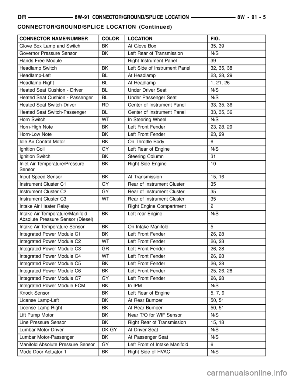
CONNECTOR NAME/NUMBER COLOR LOCATION FIG.
Glove Box Lamp and Switch BK At Glove Box 35, 39
Governor Pressure Sensor BK Left Rear of Transmission N/S
Hands Free Module Right Instrument Panel 39
Headlamp Switch BK Left Side of Instrument Panel 32, 35, 38
Headlamp-Left BL At Headlamp 23, 28, 29
Headlamp-Right BL At Headlamp 1, 21, 26
Heated Seat Cushion - Driver BL Under Driver Seat N/S
Heated Seat Cushion - Passenger BL Under Passenger Seat N/S
Heated Seat Switch-Driver RD Center of Instrument Panel 33, 35, 36
Heated Seat Switch-Passenger BL Center of Instrument Panel 33, 35, 36
Horn Switch WT In Steering Wheel N/S
Horn-High Note BK Left Front Fender 23, 28, 29
Horn-Low Note BK Left Front Fender 23, 29
Idle Air Control Motor BK On Throttle Body 6
Ignition Coil GY Left Rear of Engine N/S
Ignition Switch BK Steering Column 31
Inlet Air Temperature/Pressure
SensorBK Right Side Engine 10
Input Speed Sensor BK At Transmission 15, 16
Instrument Cluster C1 GY Rear of Instrument Cluster 35
Instrument Cluster C2 GY Rear of Instrument Cluster 35
Instrument Cluster C3 WT Rear of Instrument Cluster 35
Intake Air Heater Relay Right Engine Compartment 2
Intake Air Temperature/Manifold
Absolute Pressure Sensor (Diesel)BK Left rear Engine N/S
Intake Air Temperature Sensor BK On Intake Manifold 5
Integrated Power Module C1 BK Left Front Fender 26, 28
Integrated Power Module C2 WT Left Front Fender 26, 28
Integrated Power Module C3 GR Left Front Fender 26, 28
Integrated Power Module C4 WT Left Front Fender 26, 28
Integrated Power Module C5 BK Left Front Fender 26, 28
Integrated Power Module C6 BK Left Front Fender 25, 26, 28
Integrated Power Module C7 GY Left Front Fender 26, 28
Integrated Power Module FCM BK In IPM N/S
Knock Sensor BK Left Rear of Engine 5, 7, 9
License Lamp-Left BK At Rear Bumper 50, 51
License Lamp-Right BK At Rear Bumper 50, 51
Lift Pump Motor BK Near T/O for WIF Sensor N/S
Line Pressure Sensor BK Right Rear of Transmission 15, 18
Lumbar Motor-Driver DK GY At Driver Seat N/S
Lumbar Motor-Passenger BK At Passenger Seat N/S
Manifold Absolute Pressure Sensor GY Left Front of Intake Manifold 6
Mode Door Actuator 1 BK Right Side of HVAC N/S
DR8W-91 CONNECTOR/GROUND/SPLICE LOCATION 8W - 91 - 5
CONNECTOR/GROUND/SPLICE LOCATION (Continued)
Page 1159 of 2627
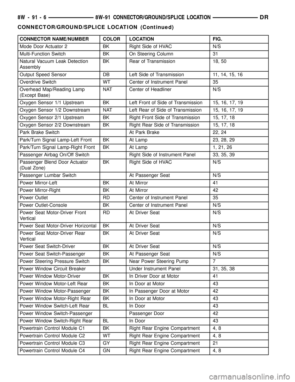
CONNECTOR NAME/NUMBER COLOR LOCATION FIG.
Mode Door Actuator 2 BK Right Side of HVAC N/S
Multi-Function Switch BK On Steering Column 31
Natural Vacuum Leak Detection
AssemblyBK Rear of Transmission 18, 50
Output Speed Sensor DB Left Side of Transmission 11, 14, 15, 16
Overdrive Switch WT Center of Instrument Panel 35
Overhead Map/Reading Lamp
(Except Base)NAT Center of Headliner N/S
Oxygen Sensor 1/1 Upstream BK Left Front of Side of Transmission 15, 16, 17, 19
Oxygen Sensor 1/2 Downstream NAT Left Rear of Side of Transmission 15, 16, 17, 19
Oxygen Sensor 2/1 Upstream BK Right Front Side of Transmission 15, 17, 18
Oxygen Sensor 2/2 Downstream BK Right Rear Side of Transmission 15, 17, 18
Park Brake Switch At Park Brake 22, 24
Park/Turn Signal Lamp-Left Front BK At Lamp 23, 28, 29
Park/Turn Signal Lamp-Right Front BK At Lamp 1, 21, 26
Passenger Airbag On/Off Switch Right Side of Instrument Panel 33, 35, 39
Passenger Blend Door Actuator
(Dual Zone)BK Right Side of HVAC N/S
Passenger Lumbar Switch At Passenger Seat N/S
Power Mirror-Left BK At Mirror 41
Power Mirror-Right BK At Mirror 42
Power Outlet RD Center of Instrument Panel 35
Power Outlet-Console BK Center of Instrument Panel N/S
Power Seat Motor-Driver Front
VerticalRD At Driver Seat N/S
Power Seat Motor-Driver Horizontal BK At Driver Seat N/S
Power Seat Motor-Driver Rear
VerticalBK At Driver Seat N/S
Power Seat Switch-Driver BK At Driver Seat N/S
Power Seat Switch-Passenger BK At Passenger Seat N/S
Power Steering Pressure Switch BK Near Power Steering Pump 7
Power Window Circuit Breaker Under Instrument Panel 31, 35, 38
Power Window Motor-Driver BK In Driver Door at Motor 41
Power Window Motor-Left Rear BK In Door at Motor 43
Power Window Motor-Passenger BK In Passenger Door at Motor 42
Power Window Motor-Right Rear BK In Door at Motor 43
Power Window Switch-Left Rear BL In Door 43
Power Window Switch-Passenger Passenger Door 42
Power Window Switch-Right Rear BL In Door 43
Powertrain Control Module C1 BK Right Rear Engine Compartment 4, 8
Powertrain Control Module C2 WT Right Rear Engine Compartment 4, 8
Powertrain Control Module C3 GY Right Rear Engine Compartment 21
Powertrain Control Module C4 GN Right Rear Engine Compartment 4, 8
8W - 91 - 6 8W-91 CONNECTOR/GROUND/SPLICE LOCATIONDR
CONNECTOR/GROUND/SPLICE LOCATION (Continued)
Page 1220 of 2627

(3) Connect the electrical connectors by pushing
straight on and rotating the connector arm inboard,
until the connector is firmly locked in place on the
module assembly.
(4) Grasp the integrated power module with two
hands and install the assembly on the battery tray
(Fig. 5).
(5) Install the integrated power module retaining
bolt and screw.
(6) Connect the gray connector on the integrated
power module housing.
(7) Install the B+ terminal cable and nut on the
integrated power module B+ terminal. Snap the
cover in place.
(8) Connect the negative and positive battery
cables.
FRONT CONTROL MODULE
DESCRIPTION
The Front Control Module (FCM) is a micro con-
troller based module located in the left front corner
of the engine compartment. On this model the inte-
grated power module must be positioned aside in
order to access the front control module. The front
control module mates to the power distribution cen-
ter to form the Integrated Power Module (IPM). Theintegrated power module connects directly to the bat-
tery and provides the primary means of circuit pro-
tection and power distribution for all vehicle
electrical systems. The front control module controls
power to some of these vehicle systems electrical and
electromechanical loads based on inputs received
from hard wired switch inputs and data received on
the PCI bus circuit (J1850).
For information on theIntegrated Power Mod-
ule Refer to the Power Distribution Sectionof
the service manual.
OPERATION
As messages are sent over the PCI bus circuit, the
front control module reads these messages and con-
trols power to some of the vehicles electrical systems
by completing the circuit to ground (low side driver)
or completing the circuit to 12 volt power (high side
driver). The following functions areControlledby
the Front Control Module:
²Headlamp Power with Voltage Regulation
²Windshield Wiper ªON/OFFº Relay Actuation
²Windshield Wiper ªHI/LOº Relay Actuation
²Windshield Washer Pump Motor
²Fog Lamp Relay Actuation
²Park Lamp Relay Actuation
²Horn Relay Actuation
The following inputs areReceived/Monitoredby
the Front Control Module:
²B+ Connection Detection
²Power Ground
²Ambient Temperature Sensing
²Ignition Switch Run
²Washer Fluid Level Switch
²Windshield Wiper Park Switch
²PCI Bus Circuit
DIAGNOSIS AND TESTING - FRONT CONTROL
MODULE
The front control module is a printed circuit board
based module with a on-board micro-processor. The
front control module interfaces with other electronic
modules in the vehicle via the Programmable Com-
munications Interface (PCI) data bus (J1850). In
order to obtain conclusive testing the Programmable
Communications Interface (PCI) data bus network
and all of the electronic modules that provide inputs
to, or receive outputs from the front control module
must be checked. All PCI (J1850) communication
faults must be resolved prior to further diagnosing
any front control module related issues.
The front control module was designed to be diag-
nosed with an appropriate diagnostic scan tool, such
as the DRB IIIt. The most reliable, efficient, and
accurate means to diagnose the front control module
Fig. 5 INTEGRATED POWER MODULE MOUNTING
TABS
1 - INTEGRATED POWER MODULE MOUNTING HOLES
2 - BATTERY TRAY ASSEMBLY
3 - FRONT CONTROL MODULE
DR8W-97 POWER DISTRIBUTION 8W - 97 - 5
INTEGRATED POWER MODULE (Continued)
Page 1233 of 2627

of oil and coolant. Can be used on threaded and
machined parts under all temperatures. This mate-
rial is used on engines with multi-layer steel (MLS)
cylinder head gaskets. This material also will pre-
vent corrosion. MopartGasket Sealant is available in
a 13 oz. aerosol can or 4oz./16 oz. can w/applicator.
FORM-IN-PLACE GASKET AND SEALER
APPLICATION
Assembling parts using a form-in-place gasket
requires care but it's easier than using precut gas-
kets.
MopartGasket Maker material should be applied
sparingly 1 mm (0.040 in.) diameter or less of sealant
to one gasket surface. Be certain the material sur-
rounds each mounting hole. Excess material can eas-
ily be wiped off. Components should be torqued in
place within 15 minutes. The use of a locating dowel
is recommended during assembly to prevent smear-
ing material off the location.
MopartEngine RTV GEN II or ATF RTV gasket
material should be applied in a continuous bead
approximately 3 mm (0.120 in.) in diameter. All
mounting holes must be circled. For corner sealing, a
3.17 or 6.35 mm (1/8 or 1/4 in.) drop is placed in the
center of the gasket contact area. Uncured sealant
may be removed with a shop towel. Components
should be torqued in place while the sealant is still
wet to the touch (within 10 minutes). The usage of a
locating dowel is recommended during assembly to
prevent smearing material off the location.
MopartGasket Sealant in an aerosol can should be
applied using a thin, even coat sprayed completely
over both surfaces to be joined, and both sides of a
gasket. Then proceed with assembly. Material in a
can w/applicator can be brushed on evenly over the
sealing surfaces. Material in an aerosol can should be
used on engines with multi-layer steel gaskets.
STANDARD PROCEDURE - ENGINE GASKET
SURFACE PREPARATION
To ensure engine gasket sealing, proper surface
preparation must be performed, especially with the
use of aluminum engine components and multi-layer
steel cylinder head gaskets.
Neveruse the following to clean gasket surfaces:
²Metal scraper
²Abrasive pad or paper to clean cylinder block
and head
²High speed power tool with an abrasive pad or a
wire brush (Fig. 2)
NOTE: Multi-Layer Steel (MLS) head gaskets require
a scratch free sealing surface.
Only use the following for cleaning gasket surfaces:²Solvent or a commercially available gasket
remover
²Plastic or wood scraper (Fig. 2)
²Drill motor with 3M RolocŸ Bristle Disc (white
or yellow) (Fig. 2)
CAUTION: Excessive pressure or high RPM (beyond
the recommended speed), can damage the sealing
surfaces. The mild (white, 120 grit) bristle disc is
recommended. If necessary, the medium (yellow, 80
grit) bristle disc may be used on cast iron surfaces
with care.
REMOVAL
(1) Disconnect the battery negative cable.
(2) Remove hood. Mark hood hinge location for
reinstallation.
(3) Remove air cleaner assembly.
(4) Remove radiator core support bracket.
(5) Remove fan shroud with viscous fan assembly.
(6) Remove drive belt.
(7) Remove A/C compressor and secure away from
engine.
(8) Remove generator and secure away from
engine.
NOTE: Do NOT remove the phenolic pulley from the
P/S pump. It is not required for P/S pump removal.
(9) Remove power steering pump with lines
attached and secure away from engine.
(10) Drain cooling system.
(11) Disconnect the heater hoses from the engine.
Fig. 2 Proper Tool Usage For Surface Preparation
1 - ABRASIVE PAD
2 - 3M ROLOCŸ BRISTLE DISC
3 - PLASTIC/WOOD SCRAPER
9 - 10 ENGINE - 3.7LDR
ENGINE - 3.7L (Continued)
Page 1235 of 2627
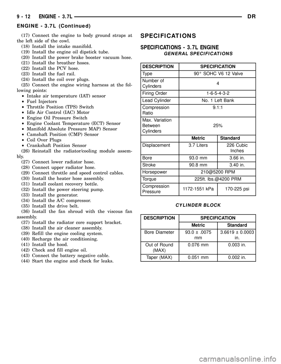
(17) Connect the engine to body ground straps at
the left side of the cowl.
(18) Install the intake manifold.
(19) Install the engine oil dipstick tube.
(20) Install the power brake booster vacuum hose.
(21) Install the breather hoses.
(22) Install the PCV hose.
(23) Install the fuel rail.
(24) Install the coil over plugs.
(25) Connect the engine wiring harness at the fol-
lowing points:
²Intake air temperature (IAT) sensor
²Fuel Injectors
²Throttle Position (TPS) Switch
²Idle Air Control (IAC) Motor
²Engine Oil Pressure Switch
²Engine Coolant Temperature (ECT) Sensor
²Manifold Absolute Pressure MAP) Sensor
²Camshaft Position (CMP) Sensor
²Coil Over Plugs
²Crankshaft Position Sensor
(26) Reinstall the radiator/cooling module assem-
bly.
(27) Connect lower radiator hose.
(28) Connect upper radiator hose.
(29) Connect throttle and speed control cables.
(30) Install the heater hose assembly.
(31) Install coolant recovery bottle.
(32) Install the power steering pump.
(33) Install the generator.
(34) Install the A/C compressor.
(35) Install the drive belt.
(36) Install the fan shroud with the viscous fan
assembly.
(37) Install the radiator core support bracket.
(38) Install the air cleaner assembly.
(39) Refill the engine cooling system.
(40) Recharge the air conditioning.
(41) Install the hood.
(42) Check and fill engine oil.
(43) Connect the battery negative cable.
(44) Start the engine and check for leaks.SPECIFICATIONS
SPECIFICATIONS - 3.7L ENGINE
GENERAL SPECIFICATIONS
DESCRIPTION SPECIFICATION
Type 90É SOHC V6 12 Valve
Number of
Cylinders4
Firing Order 1-6-5-4-3-2
Lead Cylinder No. 1 Left Bank
Compression
Ratio9.1:1
Max. Variation
Between
Cylinders25%
Metric Standard
Displacement 3.7 Liters 226 Cubic
Inches
Bore 93.0 mm 3.66 in.
Stroke 90.8 mm 3.40 in.
Horsepower 210@5200 RPM
Torque 225ft. lbs.@4200 PRM
Compression
Pressure1172-1551 kPa 170-225 psi
CYLINDER BLOCK
DESCRIPTION SPECIFICATION
Metric Standard
Bore Diameter 93.0 .0075
mm3.6619 0.0003
in.
Out of Round
(MAX)0.076 mm 0.003 in.
Taper (MAX) 0.051 mm 0.002 in.
9 - 12 ENGINE - 3.7LDR
ENGINE - 3.7L (Continued)
Page 1239 of 2627
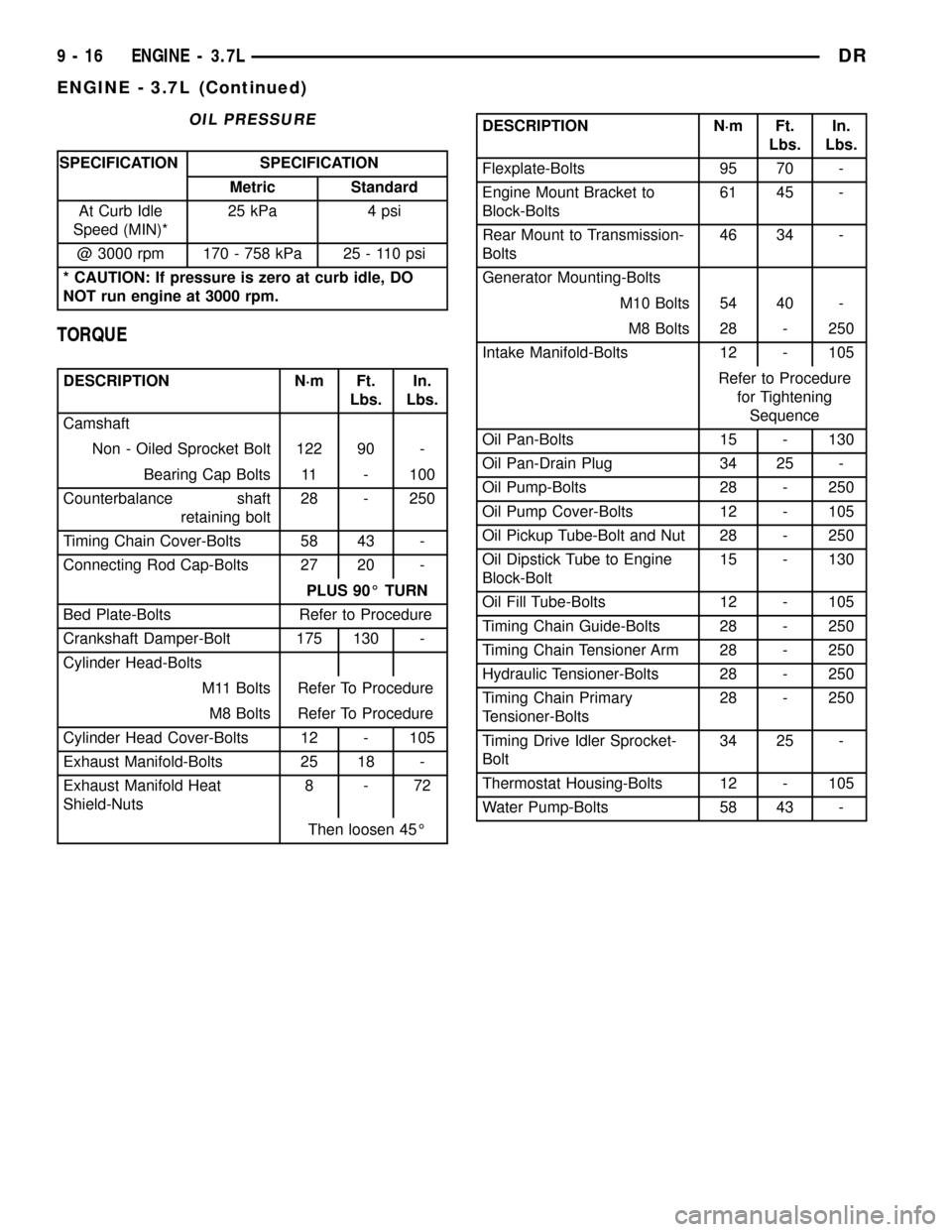
OIL PRESSURE
SPECIFICATION SPECIFICATION
Metric Standard
At Curb Idle
Speed (MIN)*25 kPa 4 psi
@ 3000 rpm 170 - 758 kPa 25 - 110 psi
* CAUTION: If pressure is zero at curb idle, DO
NOT run engine at 3000 rpm.
TORQUE
DESCRIPTION N´m Ft.
Lbs.In.
Lbs.
Camshaft
Non - Oiled Sprocket Bolt 122 90 -
Bearing Cap Bolts 11 - 100
Counterbalance shaft
retaining bolt28 - 250
Timing Chain Cover-Bolts 58 43 -
Connecting Rod Cap-Bolts 27 20 -
PLUS 90É TURN
Bed Plate-Bolts Refer to Procedure
Crankshaft Damper-Bolt 175 130 -
Cylinder Head-Bolts
M11 Bolts Refer To Procedure
M8 Bolts Refer To Procedure
Cylinder Head Cover-Bolts 12 - 105
Exhaust Manifold-Bolts 25 18 -
Exhaust Manifold Heat
Shield-Nuts8-72
Then loosen 45É
DESCRIPTION N´m Ft.
Lbs.In.
Lbs.
Flexplate-Bolts 95 70 -
Engine Mount Bracket to
Block-Bolts61 45 -
Rear Mount to Transmission-
Bolts46 34 -
Generator Mounting-Bolts
M10 Bolts 54 40 -
M8 Bolts 28 - 250
Intake Manifold-Bolts 12 - 105
Refer to Procedure
for Tightening
Sequence
Oil Pan-Bolts 15 - 130
Oil Pan-Drain Plug 34 25 -
Oil Pump-Bolts 28 - 250
Oil Pump Cover-Bolts 12 - 105
Oil Pickup Tube-Bolt and Nut 28 - 250
Oil Dipstick Tube to Engine
Block-Bolt15 - 130
Oil Fill Tube-Bolts 12 - 105
Timing Chain Guide-Bolts 28 - 250
Timing Chain Tensioner Arm 28 - 250
Hydraulic Tensioner-Bolts 28 - 250
Timing Chain Primary
Tensioner-Bolts28 - 250
Timing Drive Idler Sprocket-
Bolt34 25 -
Thermostat Housing-Bolts 12 - 105
Water Pump-Bolts 58 43 -
9 - 16 ENGINE - 3.7LDR
ENGINE - 3.7L (Continued)