1998 DODGE RAM 1500 tow bar
[x] Cancel search: tow barPage 709 of 2627

domed upper surface of the washer nozzle is visible
on the top of the plenum cover/grille panel, and the
nozzle orifice is oriented towards the windshield
glass. The washer plumbing fittings for the washer
nozzles are concealed beneath the cowl plenum cover/
grille panel. These fluidic washer nozzles are con-
structed of molded plastic. The cowl plenum cover/
grille panel must be removed from the vehicle to
access the nozzles for service. The washer nozzles
cannot be adjusted or repaired. If faulty or damaged,
they must be replaced.
OPERATION
The two washer nozzles are designed to dispense
washer fluid into the wiper pattern area on the out-
side of the windshield glass. Pressurized washer fluid
is fed to each nozzle from the washer reservoir by the
washer pump/motor unit through a single hose,
which is attached to a barbed nipple on each washer
nozzle below the cowl plenum cover/grille panel. A
fluidic matrix within the washer nozzle causes the
pressurized washer fluid to be emitted from the noz-
zle orifice as an oscillating stream to more effectively
cover a larger area of the glass to be cleaned.
REMOVAL
(1) Remove both wiper arms from the wiper pivots.
(Refer to 8 - ELECTRICAL/WIPERS/WASHERS/
WIPER ARM - REMOVAL).
(2) Unlatch and open the hood.
(3) Remove the cowl plenum cover/grille panel
from over the cowl plenum. (Refer to 23 - BODY/EX-
TERIOR/COWL GRILLE - REMOVAL).(4) From the underside of the cowl plenum cover/
grille panel, disconnect the washer nozzle hose from
the barbed nipple of the washer nozzle (Fig. 11).
(5) From the underside of the cowl plenum cover/
grille panel, release the integral snap features of the
washer nozzle and push the nozzle out through the
mounting hole toward the top side of the cowl ple-
num cover/grille panel.
(6) Remove the washer nozzle from the top of the
cowl plenum cover/grille panel.
INSTALLATION
(1) From the top of the cowl plenum cover/grille
panel, position the nipple end of the washer nozzle
through the mounting hole and engage the anti-rota-
tion tab of the nipple into the anti-rotation notch in
the mounting hole.
(2) Using hand pressure, push firmly and evenly
on the top of the washer nozzle until the integral
snap features lock into place on the underside of the
cowl plenum cover/grille panel.
(3) From the underside of the cowl plenum cover/
grille panel, reconnect the washer hose to the barbed
nipple of the washer nozzle (Fig. 11).
(4) Reinstall the washer hose for the washer noz-
zle into its routing clips on the underside of the cowl
plenum cover/grille panel.
(5) Reinstall the cowl plenum cover/grille panel
over the cowl plenum. (Refer to 23 - BODY/EXTERI-
OR/COWL GRILLE - INSTALLATION).
(6) Close and latch the hood.
Fig. 10 Washer Nozzle
1 - HOOD
2 - LATCH (2)
3 - NIPPLE
4 - ANTI-ROTATION TAB
5 - ORIFICE
Fig. 11 Washer Nozzle Remove/Install
1 - COWL PLENUM COVER/GRILLE PANEL (UNDERSIDE)
2 - ANTI-ROTATION TAB (LARGE)
3 - NIPPLE
4 - ANTI-ROTATION TAB (SMALL)
5 - PLIERS
6 - LATCH (2)
8R - 12 WIPERS/WASHERSDR
WASHER NOZZLE (Continued)
Page 746 of 2627

8W-10 POWER DISTRIBUTION
Component Page
A/C Compressor Clutch....................8W-10-17, 40
A/C Compressor Clutch Relay.................8W-10-17, 40
A/C-Heater Control....................8W-10-42, 43, 49
Adjustable Pedal Relay....................8W-10-15, 32
Adjustable Pedal Switch..................8W-10-15, 32, 42
Airbag Control Module.....................8W-10-42, 44
Airbag-Passenger On/Off Switch.................8W-10-42
Ambient Temperature Sensor.................8W-10-48, 50
Amplifier Audio..........................8W-10-31
Ashtray Lamp...........................8W-10-35
Auto Shut Down Relay....................8W-10-12, 19
Automatic Day/Night Mirror.................8W-10-41, 48
Auxiliary Battery.........................8W-10-12
Backup Lamp Switch.....................8W-10-44, 49
Battery.............................8W-10-12, 19
Blower Motor............................8W-10-52
Brake Lamp Switch....................8W-10-14, 30, 40
Capacitor..............................8W-10-22
Cigar Lighter Outlet........................8W-10-46
Circuit Breaker...........................8W-10-52
Clearance Lamp No. 1.......................8W-10-35
Clearance Lamp No. 2.......................8W-10-35
Clearance Lamp No. 3.......................8W-10-35
Clearance Lamp No. 4.......................8W-10-35
Clearance Lamp No. 5.......................8W-10-35
Clutch Interlock Brake Switch..................8W-10-37
Coil On Plug No. 1.......................8W-10-20, 23
Coil On Plug No. 2.......................8W-10-21, 22
Coil On Plug No. 3.......................8W-10-20, 23
Coil On Plug No. 4.......................8W-10-21, 22
Coil On Plug No. 5.......................8W-10-20, 23
Coil On Plug No. 6.......................8W-10-21, 22
Coil On Plug No. 7.......................8W-10-20, 23
Coil On Plug No. 8.......................8W-10-21, 22
Compass/Mini-Trip Computer...............8W-10-31, 39, 41
Condenser Fan.........................8W-10-18, 45
Condenser Fan Relay.....................8W-10-18, 45
Controller Antilock Brake.................8W-10-14, 28, 44
Data Link Connector......................8W-10-30, 50
Door Lock Switch-Passenger....................8W-10-41
Driver Door Module....................8W-10-15, 32, 52
Electric Backlight.........................8W-10-49
Electric Brake Provision....................8W-10-12, 19
Engine Control Module................8W-10-12, 26, 38, 40
Fender Lamp-Front Left......................8W-10-35
Fender Lamp-Front Right.....................8W-10-35
Fender Lamp-Rear Left......................8W-10-35
Fender Lamp-Rear Right.....................8W-10-35
Fog Lamp Relay........................8W-10-16, 36
Fog Lamp-Left...........................8W-10-36
Fog Lamp-Right..........................8W-10-36
Front Control Module . 8W-10-13, 26, 29, 30, 32, 33, 34, 36, 47, 48, 50, 51
Fuel Heater............................8W-10-53
Fuel Heater Relay.....................8W-10-18, 40, 53
Fuel Injector No. 1.......................8W-10-23, 24
Fuel Injector No. 2.......................8W-10-21, 22
Fuel Injector No. 3.......................8W-10-23, 24
Fuel Injector No. 4.......................8W-10-21, 22
Fuel Injector No. 5.......................8W-10-23, 24
Fuel Injector No. 6.......................8W-10-21, 22
Fuel Injector No. 7.......................8W-10-23, 24
Fuel Injector No. 8.......................8W-10-21, 22
Fuel Pump Module.......................8W-10-17, 39
Fuel Pump Relay......................8W-10-17, 39, 40
Fuse 1.............................8W-10-12, 19
Fuse 2...........................8W-10-12, 13, 19
Fuse 3.............................8W-10-13, 25
Fuse 4.............................8W-10-13, 25
Fuse 5.......................8W-10-12, 13, 14, 26, 27
Fuse 6...........................8W-10-13, 14, 28
Fuse 7.............................8W-10-14, 28
Fuse 8.............................8W-10-15, 29
Fuse 9.............................8W-10-13, 25
Fuse 10.............................8W-10-13, 25
Fuse 11...........................8W-10-13, 14, 30
Fuse 12...........................8W-10-18, 45, 53
Fuse 13.............................8W-10-13, 30
Fuse 14.............................8W-10-15, 37
Fuse 15...........................8W-10-16, 17, 34
Fuse 16.............................8W-10-17, 40
Fuse 17...........................8W-10-17, 18, 39
Fuse 18.............................8W-10-14, 30
Fuse 19.............................8W-10-14, 31
Fuse 20.............................8W-10-13, 25
Fuse 21.............................8W-10-14, 31
Fuse 22.............................8W-10-14, 31
Fuse 23.............................8W-10-14, 31
Fuse 24.............................8W-10-14, 30Component Page
Fuse 25.............................8W-10-14, 31
Fuse 26...............................8W-10-49
Fuse 27...........................8W-10-17, 18, 43
Fuse 28.............................8W-10-40, 41
Fuse 29...............................8W-10-46
Fuse 32.............................8W-10-17, 34
Fuse 33.............................8W-10-17, 34
Fuse 34.............................8W-10-17, 34
Fuse 35...............................8W-10-44
Fuse 36...............................8W-10-43
Fuse 37...............................8W-10-44
Fuse 38.............................8W-10-43, 44
Fuse 40...........................8W-10-15, 16, 32
Fuse 41.............................8W-10-16, 36
Fuse 42.............................8W-10-14, 32
Fuse 43.............................8W-10-14, 32
Fuse 45...........................8W-10-16, 17, 36
Fuse 46...........................8W-10-15, 16, 33
Fuse 47.............................8W-10-16, 33
Fuse 48.............................8W-10-15, 32
Fuse 49.............................8W-10-12, 19
Fuse 50.............................8W-10-26, 40
Fuse 51...........................8W-10-14, 15, 30
Fuse 52.............................8W-10-43, 44
Fuse 53...............................8W-10-41
Fusible Link............................8W-10-12
G104........................8W-10-27, 29, 47, 48, 53
G201................................8W-10-25
Generator..............................8W-10-12
Headlamp Switch.........................8W-10-36
Headlamp-Left...........................8W-10-51
Headlamp-Right..........................8W-10-51
Heated Mirror Relay......................8W-10-18, 43
Horn Relay...........................8W-10-16, 36
Horn-High Note..........................8W-10-36
Horn-Low Note...........................8W-10-36
Ignition Switch...............8W-10-13, 25, 37, 41, 44, 46, 52
Instrument Cluster............8W-10-14, 25, 30, 31, 41, 46, 52
Integrated Power Module . . 8W-10-3, 4, 12, 13, 14, 15, 16, 17, 18, 19, 25,
26, 27, 28, 29, 30, 31, 32, 33, 34, 36, 37, 39, 40, 41, 42, 43, 44, 45, 46,
47, 48, 49, 50, 51, 53
License Lamp-Left.........................8W-10-34
License Lamp-Right........................8W-10-34
Oxygen Sensor Downstream Relay..............8W-10-12, 19
Park Lamp Relay.......................8W-10-17, 34
Park/Turn Signal Lamp-Left Front..............8W-10-34, 47
Park/Turn Signal Lamp-Right Front.............8W-10-34, 47
Passenger Lumbar Switch.....................8W-10-28
Power Mirror-Left.........................8W-10-43
Power Mirror-Right........................8W-10-43
Power Outlet..........................8W-10-14, 31
Power Outlet-Console.....................8W-10-14, 32
Power Seat Switch-Driver.....................8W-10-28
Power Seat Switch-Passenger...................8W-10-28
Power Window Circuit Breaker..................8W-10-52
Powertrain Control Module . . 8W-10-18, 19, 22, 27, 31, 37, 39, 40, 45, 52
PTCNo.1 .........................8W-10-39, 40, 41
PTCNo.2 .............................8W-10-46
PTCNo.5 .............................8W-10-33
Radio..............................8W-10-30, 46
Rear Window Defogger Relay...................8W-10-49
Seat Belt Tensioner Reducer....................8W-10-46
Seat Heater Interface Module...................8W-10-32
Sentry Key Immobilizer Module..............8W-10-31, 39, 40
Starter Motor..........................8W-10-15, 37
Starter Motor Relay......................8W-10-15, 37
Tail/Stop/Turn Signal Lamp-Left...........8W-10-34, 47, 48, 50
Tail/Stop/Turn Signal Lamp-Right..........8W-10-35, 47, 48, 50
Tailgate Lamp...........................8W-10-34
Trailer Tow Connector.................8W-10-16, 17, 33, 34
Trailer Tow Connector-Add On..........8W-10-14, 31, 33, 34, 48
Trailer Tow Left Turn Relay..................8W-10-16, 33
Trailer Tow Right Turn Relay.................8W-10-16, 33
Transfer Case Control Module...............8W-10-14, 32, 37
Transfer Case Selector Switch...................8W-10-41
Transmission Control Relay................8W-10-13, 26, 27
Transmission Range Sensor................8W-10-38, 44, 49
Transmission Solenoid Assembly.................8W-10-26
Transmission Solenoid/TRS Assembly...........8W-10-27, 44, 49
Underhood Lamp..........................8W-10-30
Vistronic Fan Drive........................8W-10-43
Washer Fluid Level Switch....................8W-10-48
Washer Pump Motor-Front....................8W-10-48
Wiper High/Low Relay.....................8W-10-15, 29
Wiper Motor-Front.......................8W-10-29, 48
Wiper On/Off Relay......................8W-10-15, 29
DR8W-10 POWER DISTRIBUTION 8W - 10 - 1
Page 798 of 2627

8W-15 GROUND DISTRIBUTION
Component Page
A/C Compressor Clutch................ 8W-15-5, 8
A/C-Heater Control.................. 8W-15-9, 12
Adjustable Pedal Switch................ 8W-15-12
Airbag Control Module................. 8W-15-15
Amplifier Audio...................... 8W-15-11
Ashtray Lamp....................... 8W-15-11
Automatic Day/Night Mirror.............. 8W-15-9
Auxiliary Battery...................... 8W-15-7
Battery............................. 8W-15-7
Brake Lamp Switch.................... 8W-15-9
Brake Transmission Shift Interlock Solenoid . . 8W-15-14
Center High Mounted Stop Lamp/Cargo Lamp . 8W-15-14
Cigar Lighter Outlet................... 8W-15-12
Clearance Lamp No. 1.................. 8W-15-13
Clearance Lamp No. 2.................. 8W-15-13
Clearance Lamp No. 3.................. 8W-15-13
Clearance Lamp No. 4.................. 8W-15-13
Clearance Lamp No. 5.................. 8W-15-13
Clockspring......................... 8W-15-10
Clutch Interlock Brake Switch............. 8W-15-3
Compass/Mini-Trip Computer.............. 8W-15-9
Condenser Fan........................ 8W-15-4
Cylinder Lock Switch-Driver............. 8W-15-17
Data Link Connector.................... 8W-15-9
Data Link Connector-Engine.............. 8W-15-8
Dome Lamp......................... 8W-15-14
Door Ajar Switch-Driver................ 8W-15-17
Door Ajar Switch-Left Rear.............. 8W-15-16
Door Ajar Switch-Passenger.............. 8W-15-17
Door Ajar Switch-Right Rear............. 8W-15-16
Door Lock Motor/Ajar Switch-Driver........ 8W-15-17
Door Lock Motor/Ajar Switch-Left Rear...... 8W-15-16
Door Lock Motor/Ajar Switch-Passenger..... 8W-15-17
Door Lock Motor/Ajar Switch-Right Rear..... 8W-15-16
Door Lock Switch-Passenger.............. 8W-15-17
Driver Door Module................... 8W-15-18
EGR Solenoid......................... 8W-15-5
Electric Brake Provision................. 8W-15-4
Engine Control Module.................. 8W-15-8
Fender Lamp-Front Left................. 8W-15-2
Fender Lamp-Front Right................ 8W-15-2
Fender Lamp-Rear Left.................. 8W-15-2
Fender Lamp-Rear Right................. 8W-15-2
Fog Lamp-Left........................ 8W-15-3
Fog Lamp-Right....................... 8W-15-3
Fuel Heater.......................... 8W-15-8
Fuel Pump Module..................... 8W-15-4
G100............................... 8W-15-7
G101............................... 8W-15-7
G102............................... 8W-15-7
G104.......................... 8W-15-3, 4, 15
G105............................... 8W-15-7
G107............................. 8W-15-5, 6
G108............................... 8W-15-7
G109............................... 8W-15-7
G114............................... 8W-15-8
G120............................... 8W-15-8
G201............................ 8W-15-9, 10Component Page
G202......................... 8W-15-11, 12, 14
G204.............................. 8W-15-15
G301.............................. 8W-15-16
G302.............................. 8W-15-18
Generator.......................... 8W-15-6, 8
Glove Box Lamp And Switch............. 8W-15-12
Hands Free Module.................... 8W-15-11
Headlamp Switch..................... 8W-15-14
Headlamp-Left........................ 8W-15-3
Headlamp-Right....................... 8W-15-7
Heated Seat Cushion-Driver.............. 8W-15-18
Heated Seat Cushion-Passenger........... 8W-15-19
Heated Seat Switch-Driver............... 8W-15-12
Heated Seat Switch-Passenger............ 8W-15-12
Horn-High Note....................... 8W-15-4
Horn-Low Note........................ 8W-15-4
Ignition Switch....................... 8W-15-10
Instrument Cluster................. 8W-15-10, 14
Intake Air Heater Relay No. 1............. 8W-15-7
Intake Air Heater Relay No. 2............. 8W-15-7
Integrated Power Module............... 8W-15-3, 4
License Lamp-Left..................... 8W-15-2
License Lamp-Right.................... 8W-15-2
Lift Pump Motor....................... 8W-15-8
Natural Vacuum Leak Detection Assembly..... 8W-15-6
Overhead Map/Reading Lamp............ 8W-15-14
Oxygen Sensor 1/1 Upstream.............. 8W-15-6
Oxygen Sensor 1/2 Downstream............ 8W-15-6
Oxygen Sensor 2/1 Upstream.............. 8W-15-6
Oxygen Sensor 2/2 Downstream............ 8W-15-6
Park/Turn Signal Lamp-Left Front.......... 8W-15-4
Park/Turn Signal Lamp-Right Front......... 8W-15-7
Passenger Lumbar Switch............... 8W-15-19
Power Mirror-Left..................... 8W-15-18
Power Mirror-Right.................... 8W-15-18
Power Outlet........................ 8W-15-12
Power Outlet-Console................ 8W-15-15, 19
Power Seat Switch-Driver............... 8W-15-18
Power Seat Switch-Passenger............. 8W-15-19
Power Steering Pressure Switch............ 8W-15-5
Powertrain Control Module............. 8W-15-5, 6
Radio.............................. 8W-15-11
Seat Belt Switch-Driver................. 8W-15-16
Seat Heater Interface Module............. 8W-15-16
Sentry Key Immobilizer Module........... 8W-15-10
Speed Control Servo.................... 8W-15-3
Tail/Stop/Turn Signal Lamp-Left........... 8W-15-2
Tail/Stop/Turn Signal Lamp-Right.......... 8W-15-2
Tailgate Lamp........................ 8W-15-2
Tow/Haul Overdrive Switch............... 8W-15-9
Trailer Tow Connector................... 8W-15-4
Trailer Tow Connector-Add On............. 8W-15-4
Transfer Case Control Module............ 8W-15-15
Transfer Case Selector Switch........... 8W-15-4, 15
Vacuum Pump........................ 8W-15-7
Washer Fluid Level Switch.............. 8W-15-3, 7
Washer Pump Motor-Front............... 8W-15-7
Wiper Motor-Front..................... 8W-15-4
DR8W-15 GROUND DISTRIBUTION 8W - 15 - 1
Page 1413 of 2627
CONDITION POSSIBLE CAUSES CORRECTION
EXCESSIVE OIL CONSUMPTION OR
SPARK PLUGS OIL FOULED1. CCV System malfunction 1. (Refer to 25 - EMISSIONS
CONTROL/EVAPORATIVE
EMISSIONS - DESCRIPTION) for
correct operation
2. Defective valve stem seal(s) 2. Repair or replace seal(s)
3. Worn or broken piston rings 3. Hone cylinder bores. Install new
rings
4. Scuffed pistons/cylinder walls 4. Hone cylinder bores and replace
pistons as required
5. Carbon in oil control ring groove 5. Remove rings and de-carbon piston
6. Worn valve guides 6. Inspect/replace valve guides as
necessary
7. Piston rings fitted too tightly in
grooves7. Remove rings and check ring end
gap and side clearance. Replace if
necessary
STANDARD PROCEDURE
STANDARD PROCEDURE - REPAIR DAMAGED
OR WORN THREADS
CAUTION: Be sure that the tapped holes maintain
the original center line.
Damaged or worn threads can be repaired. Essen-
tially, this repair consists of:
²Drilling out worn or damaged threads.
²Tapping the hole with a special Heli-Coil Tap, or
equivalent.
²Installing an insert into the tapped hole to bring
the hole back to its original thread size.
STANDARD PROCEDUREÐHYDROSTATIC
LOCK
CAUTION: DO NOT use the starter motor to rotate
the crankshaft. Severe damage could occur.
When an engine is suspected of hydrostatic lock
(regardless of what caused the problem), follow the
steps below.
(1) Perform the Fuel Pressure Release Procedure
(Refer to 14 - FUEL SYSTEM/FUEL DELIVERY -
STANDARD PROCEDURE).
(2) Disconnect the negative cable(s) from the bat-
tery.
(3) Inspect air cleaner, induction system, and
intake manifold to ensure system is dry and clear of
foreign material.
(4) Place a shop towel around the spark plugs to
catch any fluid that may possibly be under pressure
in the cylinder head. Remove the spark plugs.(5) With all spark plugs removed, rotate the crank-
shaft using a breaker bar and socket.
(6) Identify the fluid in the cylinders (coolant, fuel,
oil, etc.).
(7) Be sure all fluid has been removed from the
cylinders.
(8) Repair engine or components as necessary to
prevent this problem from occurring again.
(9) Squirt a small amount of engine oil into the
cylinders to lubricate the walls. This will prevent
damage on restart.
(10) Install new spark plugs. Tighten the spark
plugs to 41 N´m (30 ft. lbs.) torque.
(11) Drain engine oil. Remove and discard the oil
filter.
(12) Install the drain plug. Tighten the plug to 34
N´m (25 ft. lbs.) torque.
(13) Install a new oil filter.
(14) Fill engine crankcase with the specified
amount and grade of oil. (Refer to LUBRICATION &
MAINTENANCE - SPECIFICATIONS).
(15) Connect the negative cable(s) to the battery.
(16) Start the engine and check for any leaks.
REMOVAL
(1) Perform the Fuel System Pressure Release pro-
cedure (Refer to 14 - FUEL SYSTEM/FUEL DELIV-
ERY - STANDARD PROCEDURE).
(2) Disconnect the battery negative cable.
(3) Remove the air cleaner resonator and duct
work as an assembly.
(4) Drain cooling system (Refer to 7 - COOLING -
STANDARD PROCEDURE).
(5) Remove the accessory drive belt (Refer to 7 -
COOLING/ACCESSORY DRIVE/DRIVE BELTS -
REMOVAL).
9 - 190 ENGINE - 5.7LDR
ENGINE - 5.7L (Continued)
Page 1463 of 2627
material to cure. This material is available in three
ounce tubes and has a shelf life of one year. After one
year this material will not properly cure. Always
inspect the package for the expiration date before
use.
MOPARtATF RTV
MopartATF RTV is a specifically designed black
silicone rubber RTV that retains adhesion and seal-
ing properties to seal components exposed to auto-
matic transmission fluid, engine coolants, and
moisture. This material is available in three ounce
tubes and has a shelf life of one year. After one year
this material will not properly cure. Always inspect
the package for the expiration date before use.
MOPARtGASKET MAKER
MopartGasket Maker is an anaerobic type gasket
material. The material cures in the absence of air
when squeezed between two metallic surfaces. It will
not cure if left in the uncovered tube. The anaerobic
material is for use between two machined surfaces.
Do not use on flexible metal flanges.
MOPARtGASKET SEALANT
MopartGasket Sealant is a slow drying, perma-
nently soft sealer. This material is recommended for
sealing threaded fittings and gaskets against leakage
of oil and coolant. Can be used on threaded and
machined parts under all temperatures. This mate-
rial is used on engines with multi-layer steel (MLS)
cylinder head gaskets. This material also will pre-
vent corrosion. MopartGasket Sealant is available in
a 13 oz. aerosol can or 4oz./16 oz. can w/applicator.
FORM-IN-PLACE GASKET AND SEALER
APPLICATION
Assembling parts using a form-in-place gasket
requires care but it's easier than using precut gas-
kets.
MopartGasket Maker material should be applied
sparingly 1 mm (0.040 in.) diameter or less of sealant
to one gasket surface. Be certain the material sur-
rounds each mounting hole. Excess material can eas-
ily be wiped off. Components should be torqued in
place within 15 minutes. The use of a locating dowel
is recommended during assembly to prevent smear-
ing material off the location.
MopartEngine RTV GEN II or ATF RTV gasket
material should be applied in a continuous bead
approximately 3 mm (0.120 in.) in diameter. All
mounting holes must be circled. For corner sealing, a
3.17 or 6.35 mm (1/8 or 1/4 in.) drop is placed in the
center of the gasket contact area. Uncured sealant
may be removed with a shop towel. Components
should be torqued in place while the sealant is still
wet to the touch (within 10 minutes). The usage of a
locating dowel is recommended during assembly to
prevent smearing material off the location.MopartGasket Sealant in an aerosol can should be
applied using a thin, even coat sprayed completely
over both surfaces to be joined, and both sides of a
gasket. Then proceed with assembly. Material in a
can w/applicator can be brushed on evenly over the
sealing surfaces. Material in an aerosol can should be
used on engines with multi-layer steel gaskets.
STANDARD PROCEDURE - REPAIR DAMAGED
OR WORN THREADS
CAUTION: Be sure that the tapped holes maintain
the original center line.
Damaged or worn threads can be repaired. Essen-
tially, this repair consists of:
²Drilling out worn or damaged threads.
²Tapping the hole with a special Heli-Coil Tap, or
equivalent.
²Installing an insert into the tapped hole to bring
the hole back to its original thread size.
STANDARD PROCEDUREÐHYDROSTATIC
LOCK
CAUTION: DO NOT use the starter motor to rotate
the crankshaft. Severe damage could occur.
When an engine is suspected of hydrostatic lock
(regardless of what caused the problem), follow the
steps below.
(1) Disconnect the negative cable(s) from the bat-
tery.
(2) Inspect air cleaner, induction system, and
intake manifold to ensure system is dry and clear of
foreign material.
(3) Place a shop towel around the fuel injectors to
catch any fluid that may possibly be under pressure
in the cylinder head. Remove the fuel injectors (Refer
to 14 - FUEL SYSTEM/FUEL INJECTION/FUEL
INJECTOR - REMOVAL).
(4) With all injectors removed, rotate the crank-
shaft using the crankshaft barring tool (PN 7471±B).
(5) Identify the fluid in the cylinders (coolant, fuel,
oil, etc.).
(6) Be sure all fluid has been removed from the
cylinders.
(7) Repair engine or components as necessary to
prevent this problem from occurring again.
(8) Squirt a small amount of engine oil into the
cylinders to lubricate the walls. This will prevent
damage on restart.
(9) Install fuel injectors (Refer to 14 - FUEL SYS-
TEM/FUEL INJECTION/FUEL INJECTOR -
INSTALLATION).
9 - 240 ENGINE 5.9L DIESELDR
ENGINE 5.9L DIESEL (Continued)
Page 1499 of 2627
(6) Apply a bead of MopartSilicone Rubber Adhe-
sive Sealant or equivalent to the gear housing cover
sealing surface.
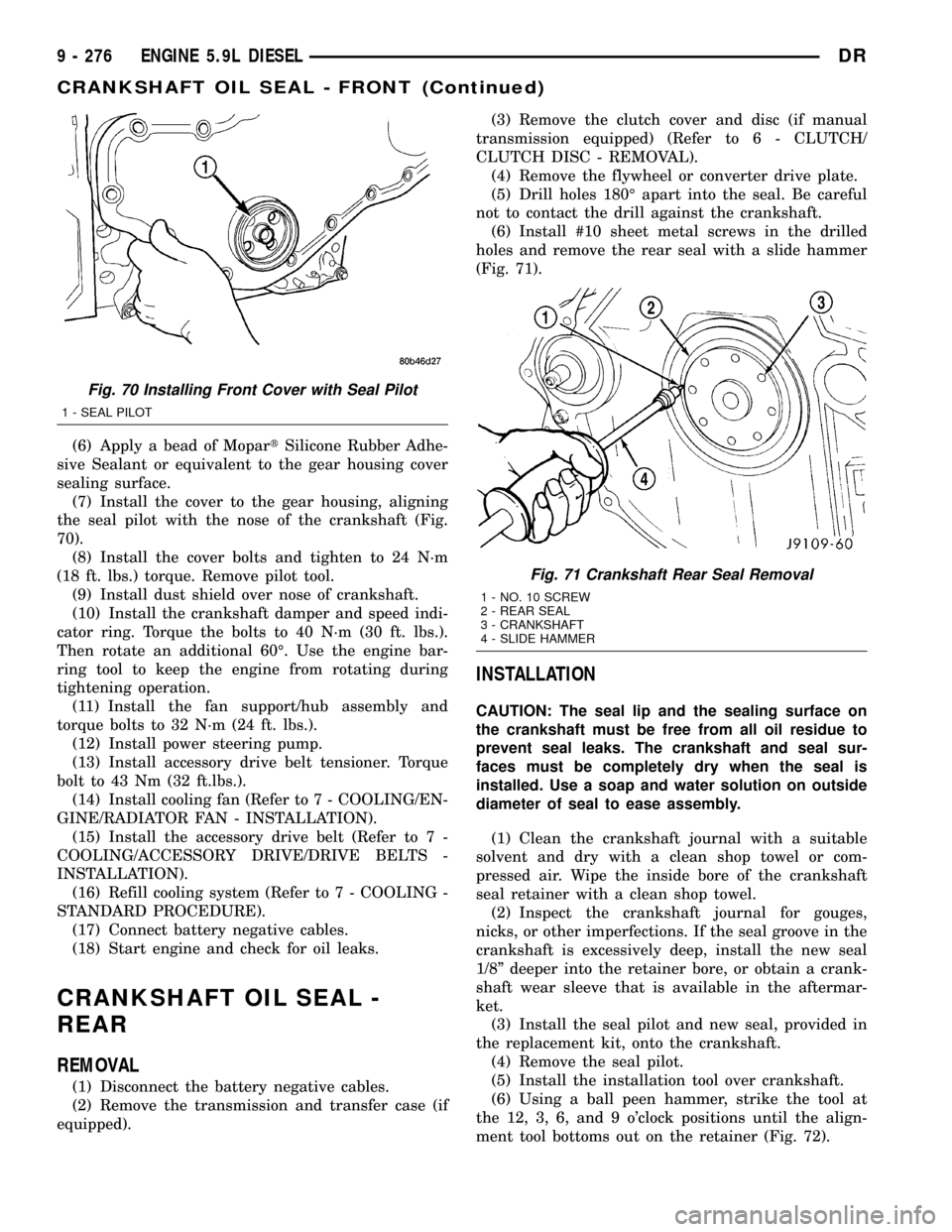
(7) Install the cover to the gear housing, aligning
the seal pilot with the nose of the crankshaft (Fig.
70).
(8) Install the cover bolts and tighten to 24 N´m
(18 ft. lbs.) torque. Remove pilot tool.
(9) Install dust shield over nose of crankshaft.
(10) Install the crankshaft damper and speed indi-
cator ring. Torque the bolts to 40 N´m (30 ft. lbs.).
Then rotate an additional 60É. Use the engine bar-
ring tool to keep the engine from rotating during
tightening operation.
(11) Install the fan support/hub assembly and
torque bolts to 32 N´m (24 ft. lbs.).
(12) Install power steering pump.
(13) Install accessory drive belt tensioner. Torque
bolt to 43 Nm (32 ft.lbs.).
(14) Install cooling fan (Refer to 7 - COOLING/EN-
GINE/RADIATOR FAN - INSTALLATION).
(15) Install the accessory drive belt (Refer to 7 -
COOLING/ACCESSORY DRIVE/DRIVE BELTS -
INSTALLATION).
(16) Refill cooling system (Refer to 7 - COOLING -
STANDARD PROCEDURE).
(17) Connect battery negative cables.
(18) Start engine and check for oil leaks.
CRANKSHAFT OIL SEAL -
REAR
REMOVAL
(1) Disconnect the battery negative cables.
(2) Remove the transmission and transfer case (if
equipped).(3) Remove the clutch cover and disc (if manual
transmission equipped) (Refer to 6 - CLUTCH/
CLUTCH DISC - REMOVAL).
(4) Remove the flywheel or converter drive plate.
(5) Drill holes 180É apart into the seal. Be careful
not to contact the drill against the crankshaft.
(6) Install #10 sheet metal screws in the drilled
holes and remove the rear seal with a slide hammer
(Fig. 71).
INSTALLATION
CAUTION: The seal lip and the sealing surface on
the crankshaft must be free from all oil residue to
prevent seal leaks. The crankshaft and seal sur-
faces must be completely dry when the seal is
installed. Use a soap and water solution on outside
diameter of seal to ease assembly.
(1) Clean the crankshaft journal with a suitable
solvent and dry with a clean shop towel or com-
pressed air. Wipe the inside bore of the crankshaft
seal retainer with a clean shop towel.
(2) Inspect the crankshaft journal for gouges,
nicks, or other imperfections. If the seal groove in the
crankshaft is excessively deep, install the new seal
1/8º deeper into the retainer bore, or obtain a crank-
shaft wear sleeve that is available in the aftermar-
ket.
(3) Install the seal pilot and new seal, provided in
the replacement kit, onto the crankshaft.
(4) Remove the seal pilot.
(5) Install the installation tool over crankshaft.
(6) Using a ball peen hammer, strike the tool at
the 12, 3, 6, and 9 o'clock positions until the align-
ment tool bottoms out on the retainer (Fig. 72).
Fig. 70 Installing Front Cover with Seal Pilot
1 - SEAL PILOT
Fig. 71 Crankshaft Rear Seal Removal
1 - NO. 10 SCREW
2 - REAR SEAL
3 - CRANKSHAFT
4 - SLIDE HAMMER
9 - 276 ENGINE 5.9L DIESELDR
CRANKSHAFT OIL SEAL - FRONT (Continued)
Page 1567 of 2627
TRANSMISSION
CROSSMEMBER
REMOVAL
(1) Raise and support the vehicle. (Refer to
LUBRICATION & MAINTENANCE/HOISTING -
STANDARD PROCEDURE)
(2) Remove the transfercase skid plate, if
equipped. (Refer to 13 - FRAME & BUMPERS/
FRAME/TRANSFER CASE SKID PLATE -
REMOVAL)
(3) Support the transmission with a suitable lifting
device.
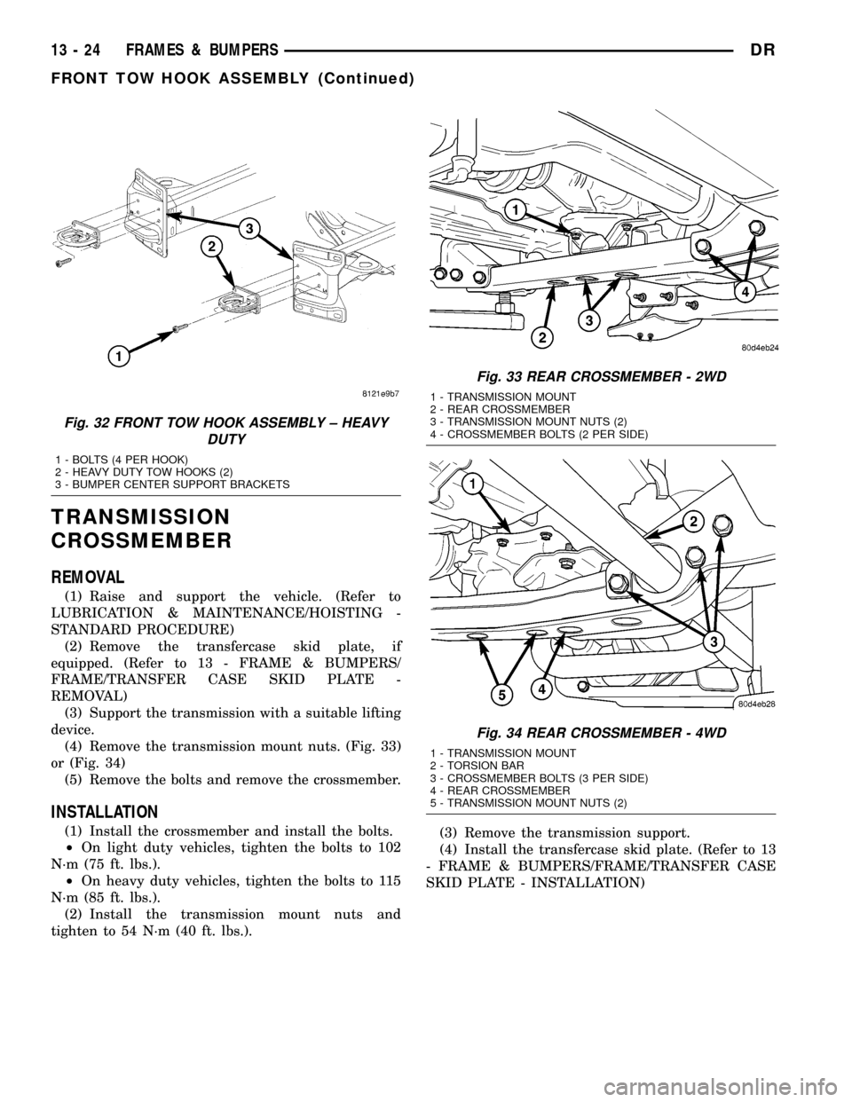
(4) Remove the transmission mount nuts. (Fig. 33)
or (Fig. 34)
(5) Remove the bolts and remove the crossmember.
INSTALLATION
(1) Install the crossmember and install the bolts.
²On light duty vehicles, tighten the bolts to 102
N´m (75 ft. lbs.).
²On heavy duty vehicles, tighten the bolts to 115
N´m (85 ft. lbs.).
(2) Install the transmission mount nuts and
tighten to 54 N´m (40 ft. lbs.).(3) Remove the transmission support.
(4) Install the transfercase skid plate. (Refer to 13
- FRAME & BUMPERS/FRAME/TRANSFER CASE
SKID PLATE - INSTALLATION)
Fig. 32 FRONT TOW HOOK ASSEMBLY ± HEAVY
DUTY
1 - BOLTS (4 PER HOOK)
2 - HEAVY DUTY TOW HOOKS (2)
3 - BUMPER CENTER SUPPORT BRACKETS
Fig. 33 REAR CROSSMEMBER - 2WD
1 - TRANSMISSION MOUNT
2 - REAR CROSSMEMBER
3 - TRANSMISSION MOUNT NUTS (2)
4 - CROSSMEMBER BOLTS (2 PER SIDE)
Fig. 34 REAR CROSSMEMBER - 4WD
1 - TRANSMISSION MOUNT
2 - TORSION BAR
3 - CROSSMEMBER BOLTS (3 PER SIDE)
4 - REAR CROSSMEMBER
5 - TRANSMISSION MOUNT NUTS (2)
13 - 24 FRAMES & BUMPERSDR
FRONT TOW HOOK ASSEMBLY (Continued)
Page 1823 of 2627
(10) Install reverse countershaft rear bearing onto
the countershaft reverse gear assembly with Installer
C-4652 and Handle C-4171.
(11) Install reverse idler gear rear bearing, bearing
spacer, front bearing, and front thrust washer onto
the idler gear shaft.
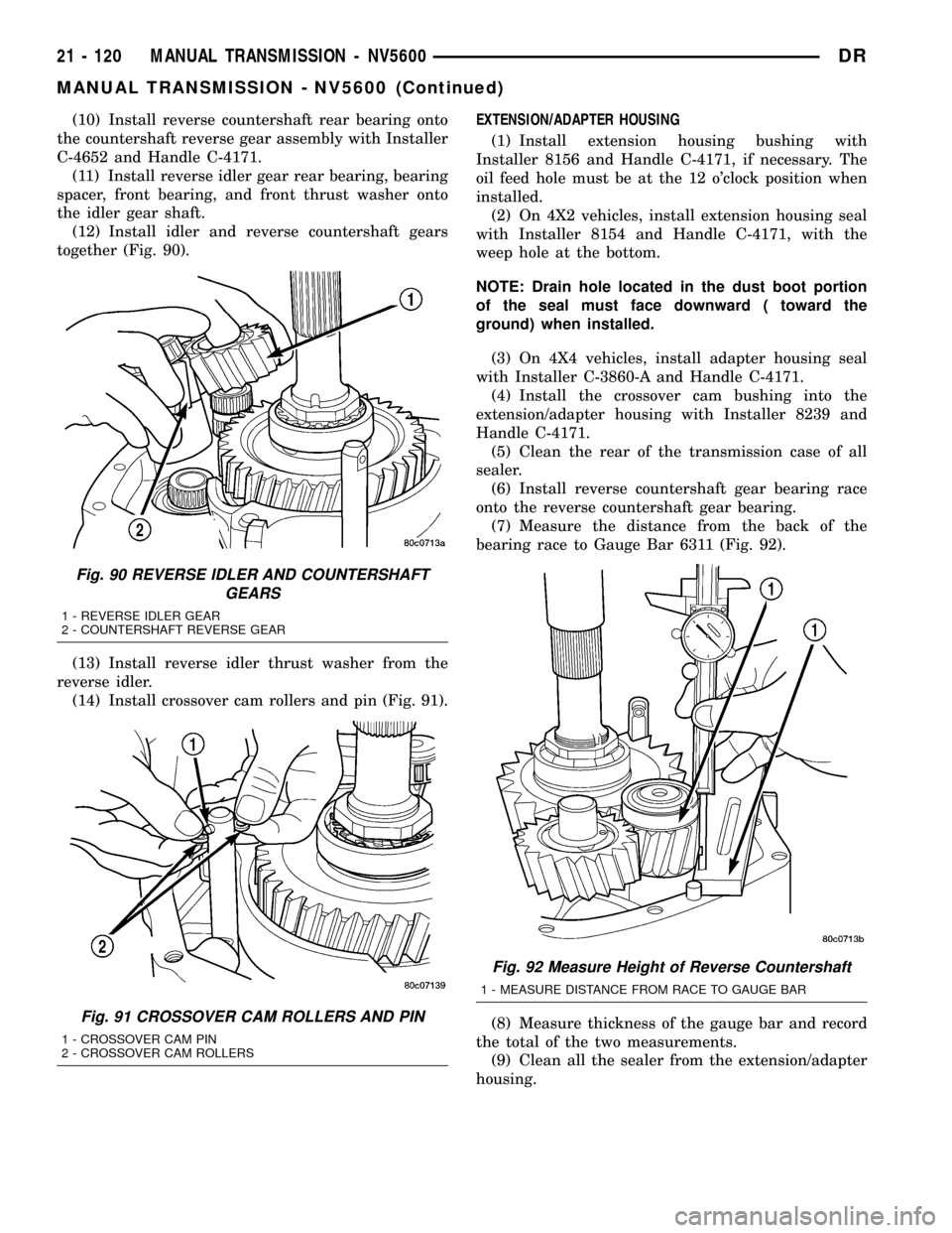
(12) Install idler and reverse countershaft gears
together (Fig. 90).
(13) Install reverse idler thrust washer from the
reverse idler.
(14) Install crossover cam rollers and pin (Fig. 91).EXTENSION/ADAPTER HOUSING
(1) Install extension housing bushing with
Installer 8156 and Handle C-4171, if necessary. The
oil feed hole must be at the 12 o'clock position when
installed.
(2) On 4X2 vehicles, install extension housing seal
with Installer 8154 and Handle C-4171, with the
weep hole at the bottom.
NOTE: Drain hole located in the dust boot portion
of the seal must face downward ( toward the
ground) when installed.
(3) On 4X4 vehicles, install adapter housing seal
with Installer C-3860-A and Handle C-4171.
(4) Install the crossover cam bushing into the
extension/adapter housing with Installer 8239 and
Handle C-4171.
(5) Clean the rear of the transmission case of all
sealer.
(6) Install reverse countershaft gear bearing race
onto the reverse countershaft gear bearing.
(7) Measure the distance from the back of the
bearing race to Gauge Bar 6311 (Fig. 92).
(8) Measure thickness of the gauge bar and record
the total of the two measurements.
(9) Clean all the sealer from the extension/adapter
housing.
Fig. 90 REVERSE IDLER AND COUNTERSHAFT
GEARS
1 - REVERSE IDLER GEAR
2 - COUNTERSHAFT REVERSE GEAR
Fig. 91 CROSSOVER CAM ROLLERS AND PIN
1 - CROSSOVER CAM PIN
2 - CROSSOVER CAM ROLLERS
Fig. 92 Measure Height of Reverse Countershaft
1 - MEASURE DISTANCE FROM RACE TO GAUGE BAR
21 - 120 MANUAL TRANSMISSION - NV5600DR
MANUAL TRANSMISSION - NV5600 (Continued)