1998 DODGE RAM 1500 engine coolant
[x] Cancel search: engine coolantPage 26 of 2627

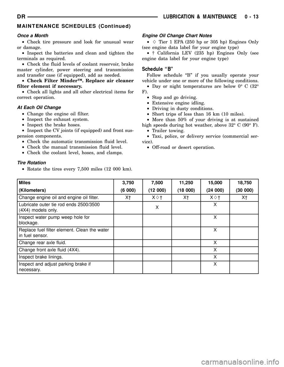
Once a Month
²Check tire pressure and look for unusual wear
or damage.
²Inspect the batteries and clean and tighten the
terminals as required.
²Check the fluid levels of coolant reservoir, brake
master cylinder, power steering and transmission
and transfer case (if equipped), add as needed.
²Check Filter MinderŸ. Replace air cleaner
filter element if necessary.
²Check all lights and all other electrical items for
correct operation.
At Each Oil Change
²Change the engine oil filter.
²Inspect the exhaust system.
²Inspect the brake hoses.
²Inspect the CV joints (if equipped) and front sus-
pension components.
²Check the automatic transmission fluid level.
²Check the manual transmission fluid level.
²Check the coolant level, hoses, and clamps.
Tire Rotation
²Rotate the tires every 7,500 miles (12 000 km).
Engine Oil Change Chart Notes
²LTier 1 EPA (250 hp or 305 hp) Engines Only
(see engine data label for your engine type)
²² California LEV (235 hp) Engines Only (see
engine data label for your engine type)
Schedule ªBº
Follow schedule ªBº if you usually operate your
vehicle under one or more of the following conditions.
²Day or night temperatures are below 0É C (32É
F).
²Stop and go driving.
²Extensive engine idling.
²Driving in dusty conditions.
²Short trips of less than 16 km (10 miles).
²More than 50% of your driving is at sustained
high speeds during hot weather, above 32É C (90É F).
²Trailer towing.
²Taxi, police, or delivery service (commercial ser-
vice).
²Off-road or desert operation.
Miles 3,750 7,500 11,250 15,000 18,750
(Kilometers) (6 000) (12 000) (18 000) (24 000) (30 000)
Change engine oil and engine oil filter. X² XL²X²XL²X²
Lubricate outer tie rod ends 2500/3500
(4X4) models only.XX
Inspect water pump weep hole for
blockage.X
Replace fuel filter element. Clean the water
in fuel sensor.X
Change rear axle fluid. X
Change front axle fluid (4X4). X
Inspect brake linings.X
Inspect and adjust parking brake if
necessary.X
DRLUBRICATION & MAINTENANCE 0 - 13
MAINTENANCE SCHEDULES (Continued)
Page 29 of 2627

Miles 97,500 100,000 101,250 105,000 108,750 112,500
(Kilometers) (156 000) (160 000) (162 000) (168 000) (174 000) (180 000)
Change engine oil and engine
oil filter.XL²X²XL²X² XL²
Lubricate outer tie rod ends
2500/3500 (4X4) models only.XXX
Flush and replace engine
coolant.X
Inspect drive belt, replace as
required.X
Inspect water pump weep
hole for blockage.X
Replace fuel filter element.
Clean the water in fuel sensor.X
Change rear axle fluid. X
Change front axle fluid (4X4). X
Inspect brake linings. X
Inspect and adjust parking
brake if necessary.X
Miles 116,250 120,000 123,750 127,500 131,250 135,000
(Kilometers) (186 000) (192 000) (198 000) (204 000) (210 000) (216 000)
Change engine oil and engine
oil filter.X² XL²X²XL²X² XL²
Lubricate outer tie rod ends
2500/3500 (4X4) models only.XXX
Clean engine air filter canister.X
Adjust valve lash clearance.X
Inspect drive belts, replace as
required.X
Drain and refill transfer case
fluid (4X4).X
Inspect fan hub. X
Inspect damper. X
Inspect water pump weep
hole for blockage.XX
Replace fuel filter element.
Clean the water in fuel sensor.XX
Inspect front wheel bearings. X
Change rear axle fluid. X X
Change front axle fluid (4X4). X X
Inspect brake linings. X X
Inspect and adjust parking
brake if necessary.XX
Drain and refill automatic
transmission fluid. Replace
filter and adjust bands.X
0 - 16 LUBRICATION & MAINTENANCEDR
MAINTENANCE SCHEDULES (Continued)
Page 30 of 2627

²LTier 1 EPA (250 hp or 305 hp) Engines Only
(see engine data label for your engine type)
²² California LEV (235 hp) Engines Only (see
engine data label for your engine type)Inspection and service should also be performed
anytime a malfunction is observed or suspected.
Schedule ªAº
Miles 7,500 15,000 22,500 30,000 37,500
(Kilometers) (12 000) (24 000) (36 000) (48 000) (60 000)
[Months] [6] [12] [18] [24] [30]
Change engine oil and engine oil filter. X² XL²X²XL²X²
Lubricate outer tie rod ends 2500/3500
(4X4) models only.XXXX X
Check transfer case fluid level (4X4). X
Inspect water pump weep hole for blockage X X
Replace fuel filter element. Clean the water
in fuel sensor.XX
Inspect drive belts, replace as necessary. X
Inspect brake linings. X
Inspect and adjust parking brake if
necessary.X
Inspect fan hub.X
Inspect damper.X
Inspect front wheel bearings. X
Miles 45,000 52,500 60,000 67,500 75,000
(Kilometers) (72 000) (84 000) (96 000) (108 000) (120 000)
[Months] [36] [42] [48] [54] [60]
Change engine oil and engine oil filter. XL²X²XL²X² XL²
Lubricate outer tie rod ends 2500/3500
(4X4) models only.XXXX X
Check transfer case fluid level. X
Flush and replace engine coolant at 60
months, regardless of mileage.X
Inspect drive belts, replace as necessary. X X
Inspect water pump weep hole for blockage X X X
Replace fuel filter element. Clean the water
in fuel sensor.XX
Inspect brake linings. X X
Inspect and adjust parking brake if
necessary.XX
Inspect fan hub. X
Inspect damper. X
Inspect front wheel bearings. X
Replace fuel filter element. Clean the water
in fuel sensorX
DRLUBRICATION & MAINTENANCE 0 - 17
MAINTENANCE SCHEDULES (Continued)
Page 31 of 2627
![DODGE RAM 1500 1998 2.G Workshop Manual Miles 82,500 90,000 97,500 100,000 105,000
(Kilometers) (132 000) (144 000) (156 000) (160 000) (168 000)
[Months] [66] [72] [78] [84]
Change engine oil and engine oil filter. X² XL²X² XL²
Lubrica DODGE RAM 1500 1998 2.G Workshop Manual Miles 82,500 90,000 97,500 100,000 105,000
(Kilometers) (132 000) (144 000) (156 000) (160 000) (168 000)
[Months] [66] [72] [78] [84]
Change engine oil and engine oil filter. X² XL²X² XL²
Lubrica](/manual-img/12/5702/w960_5702-30.png)
Miles 82,500 90,000 97,500 100,000 105,000
(Kilometers) (132 000) (144 000) (156 000) (160 000) (168 000)
[Months] [66] [72] [78] [84]
Change engine oil and engine oil filter. X² XL²X² XL²
Lubricate outer tie rod ends 2500/3500
(4X4) models only.XXXX X
Flush and replace engine coolant, if not
done at 60 mos.X
Check transfer case fluid level (4X4). X
Inspect drive belt, replace as required. X
Inspect fan hub. X
Inspect damper. X
Inspect water pump weep hole for
blockage.XX
Replace fuel filter element. Clean the water
in fuel sensor.XX
Inspect front wheel bearings. X
Inspect brake linings. X
Inspect and adjust parking brake if
necessary.X
Drain and refill automatic transmission fluid.
Replace filter and adjust bands.X
Miles 112,500 120,000 127,500 135,000 142,500 150,000
(Kilometers) (181 000) (193 000) (205 000) (217 000) (229 000) (241 000)
[Months] [90] [96] [102] [108] [114] [150]
Change engine oil and engine
oil filter.X² XL²X²XL²X² XL²
Lubricate outer tie rod ends
2500/3500 (4X4) models only.XXXXX X
Flush and replace engine
coolant, if it has been 160
000 km (100, 000 miles) or 60
months since last change.X
Inspect drive belt, replace as
required.XX
Drain and refill transfer case
fluid (4X4).X
Check tranfer case fluid level
(4X4).X
Inspect fan hub. X X
Inspect damper. X X
Inspect water pump weep
hole for blockage.XXX
Replace fuel filter element.
Clean the water in fuel
sensor.XXX
0 - 18 LUBRICATION & MAINTENANCEDR
MAINTENANCE SCHEDULES (Continued)
Page 316 of 2627

COOLING
TABLE OF CONTENTS
page page
COOLING
DESCRIPTION
DESCRIPTION - COOLING SYSTEM FLOW
3.7L/4.7L/5.7L ENGINE..................1
DESCRIPTION - COOLING SYSTEM FLOW -
5.9L DIESEL..........................3
DESCRIPTION - HOSE CLAMPS...........3
OPERATION
OPERATION - COOLING SYSTEM.........5
OPERATION - HOSE CLAMPS............5
DIAGNOSIS AND TESTING
DIAGNOSIS AND TESTINGÐON-BOARD
DIAGNOSTICS (OBD)...................5
DIAGNOSIS AND TESTING - COOLING
SYSTEM - TESTING FOR LEAKS..........5
DIAGNOSIS AND TESTING - COOLING
SYSTEM DIESEL ENGINE................7
DIAGNOSIS AND TESTING - PRELIMINARY
CHECKS............................10
STANDARD PROCEDURE
STANDARD PROCEDURE - COOLANT
LEVEL CHECK........................17STANDARD PROCEDURE - COOLING
SYSTEM CLEANING/REVERSE FLUSHING . . 17
STANDARD PROCEDURE - DRAINING
COOLING SYSTEM - ALL GAS ENGINES . . . 17
STANDARD PROCEDURE - REFILLING
COOLING SYSTEM - ALL GAS ENGINES . . . 18
STANDARD PROCEDURE - DRAINING
COOLING SYSTEM 5.9L DIESEL ENGINE . . . 18
STANDARD PROCEDURE - REFILLING
COOLING SYSTEM 5.9L DIESEL ENGINE . . . 19
STANDARD PROCEDURE - ADDING
ADDITIONAL COOLANT.................19
SPECIFICATIONS
TORQUE............................19
SPECIFICATIONS -....................20
SPECIAL TOOLS
COOLING...........................20
ACCESSORY DRIVE......................21
ENGINE...............................30
TRANSMISSION.........................67
COOLING
DESCRIPTION
DESCRIPTION - COOLING SYSTEM FLOW
3.7L/4.7L/5.7L ENGINE
The cooling system regulates engine operating tem-
perature. It allows the engine to reach normal oper-
ating temperature as quickly as possible. It also
maintains normal operating temperature and pre-
vents overheating.The cooling system provides a means of heating
the passenger compartment and cooling the auto-
matic transmission fluid (if equipped). The cooling
system is pressurized and uses a centrifugal water
pump to circulate coolant through the system. The
coolant recovery/reserve system utilizes an ambient
overflow bottle (Fig. 2).
An optional factory installed maximum duty cool-
ing package is available on most models. This pack-
age will provide additional cooling capacity for
vehicles used under extreme conditions such as
trailer towing in high ambient temperatures (Fig. 1).
DRCOOLING 7 - 1
Page 317 of 2627

Fig. 1 Engine Cooling System Flow - 3.7L/4.7L
1 - LH CYL. HEAD
2 - BLEED
3 - THERMOSTAT LOCATION
4 - RH CYL. HEAD
5 - RH BANK CYL. BLOCK6 - LH BANK CYL. BLOCK
7 - COOLANT TEMP. SENSOR
8 - FROM HEATER CORE
9 - TO HEATER CORE
7 - 2 COOLINGDR
COOLING (Continued)
Page 318 of 2627

DESCRIPTION - COOLING SYSTEM FLOW -
5.9L DIESEL
The diesel engine cooling system consists of :
²Cross-flow radiator
²Belt driven water pump
²Cooling fan (attached to the electronic viscous
fan drive)
²Belt driven Electronic viscous fan drive
²Two piece fan shroud
²Radiator pressure cap
²Vertically mounted thermostat
²Coolant reserve/recovery system
²Transmission oil cooler
²Coolant
Coolant flow circuits for the 5.9L diesel engine are
shown in (Fig. 3).
DESCRIPTION - HOSE CLAMPS
The cooling system utilizes spring type hose
clamps. If a spring type clamp replacement is neces-
sary, replace with the original Mopartequipment
spring type clamp.
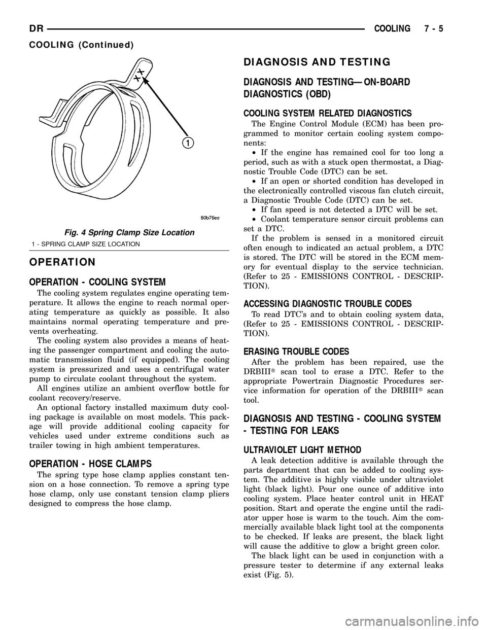
CAUTION: A number or letter is stamped into the
tongue of constant tension clamps. If replacement
is necessary, use only a original equipment clamp
with matching number or letter and ensure the
clamp has the same size width (Fig. 4).
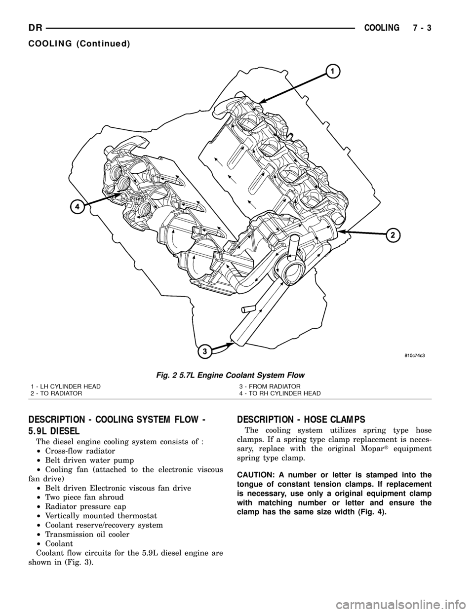
Fig. 2 5.7L Engine Coolant System Flow
1 - LH CYLINDER HEAD
2 - TO RADIATOR3 - FROM RADIATOR
4 - TO RH CYLINDER HEAD
DRCOOLING 7 - 3
COOLING (Continued)
Page 320 of 2627

OPERATION
OPERATION - COOLING SYSTEM
The cooling system regulates engine operating tem-
perature. It allows the engine to reach normal oper-
ating temperature as quickly as possible. It also
maintains normal operating temperature and pre-
vents overheating.
The cooling system also provides a means of heat-
ing the passenger compartment and cooling the auto-
matic transmission fluid (if equipped). The cooling
system is pressurized and uses a centrifugal water
pump to circulate coolant throughout the system.
All engines utilize an ambient overflow bottle for
coolant recovery/reserve.
An optional factory installed maximum duty cool-
ing package is available on most models. This pack-
age will provide additional cooling capacity for
vehicles used under extreme conditions such as
trailer towing in high ambient temperatures.
OPERATION - HOSE CLAMPS
The spring type hose clamp applies constant ten-
sion on a hose connection. To remove a spring type
hose clamp, only use constant tension clamp pliers
designed to compress the hose clamp.
DIAGNOSIS AND TESTING
DIAGNOSIS AND TESTINGÐON-BOARD
DIAGNOSTICS (OBD)
COOLING SYSTEM RELATED DIAGNOSTICS
The Engine Control Module (ECM) has been pro-
grammed to monitor certain cooling system compo-
nents:
²If the engine has remained cool for too long a
period, such as with a stuck open thermostat, a Diag-
nostic Trouble Code (DTC) can be set.
²If an open or shorted condition has developed in
the electronically controlled viscous fan clutch circuit,
a Diagnostic Trouble Code (DTC) can be set.
²If fan speed is not detected a DTC will be set.
²Coolant temperature sensor circuit problems can
set a DTC.
If the problem is sensed in a monitored circuit
often enough to indicated an actual problem, a DTC
is stored. The DTC will be stored in the ECM mem-
ory for eventual display to the service technician.
(Refer to 25 - EMISSIONS CONTROL - DESCRIP-
TION).
ACCESSING DIAGNOSTIC TROUBLE CODES
To read DTC's and to obtain cooling system data,
(Refer to 25 - EMISSIONS CONTROL - DESCRIP-
TION).
ERASING TROUBLE CODES
After the problem has been repaired, use the
DRBIIItscan tool to erase a DTC. Refer to the
appropriate Powertrain Diagnostic Procedures ser-
vice information for operation of the DRBIIItscan
tool.
DIAGNOSIS AND TESTING - COOLING SYSTEM
- TESTING FOR LEAKS
ULTRAVIOLET LIGHT METHOD
A leak detection additive is available through the
parts department that can be added to cooling sys-
tem. The additive is highly visible under ultraviolet
light (black light). Pour one ounce of additive into
cooling system. Place heater control unit in HEAT
position. Start and operate the engine until the radi-
ator upper hose is warm to the touch. Aim the com-
mercially available black light tool at the components
to be checked. If leaks are present, the black light
will cause the additive to glow a bright green color.
The black light can be used in conjunction with a
pressure tester to determine if any external leaks
exist (Fig. 5).
Fig. 4 Spring Clamp Size Location
1 - SPRING CLAMP SIZE LOCATION
DRCOOLING 7 - 5
COOLING (Continued)