1998 DODGE RAM 1500 Passenger Window
[x] Cancel search: Passenger WindowPage 1082 of 2627
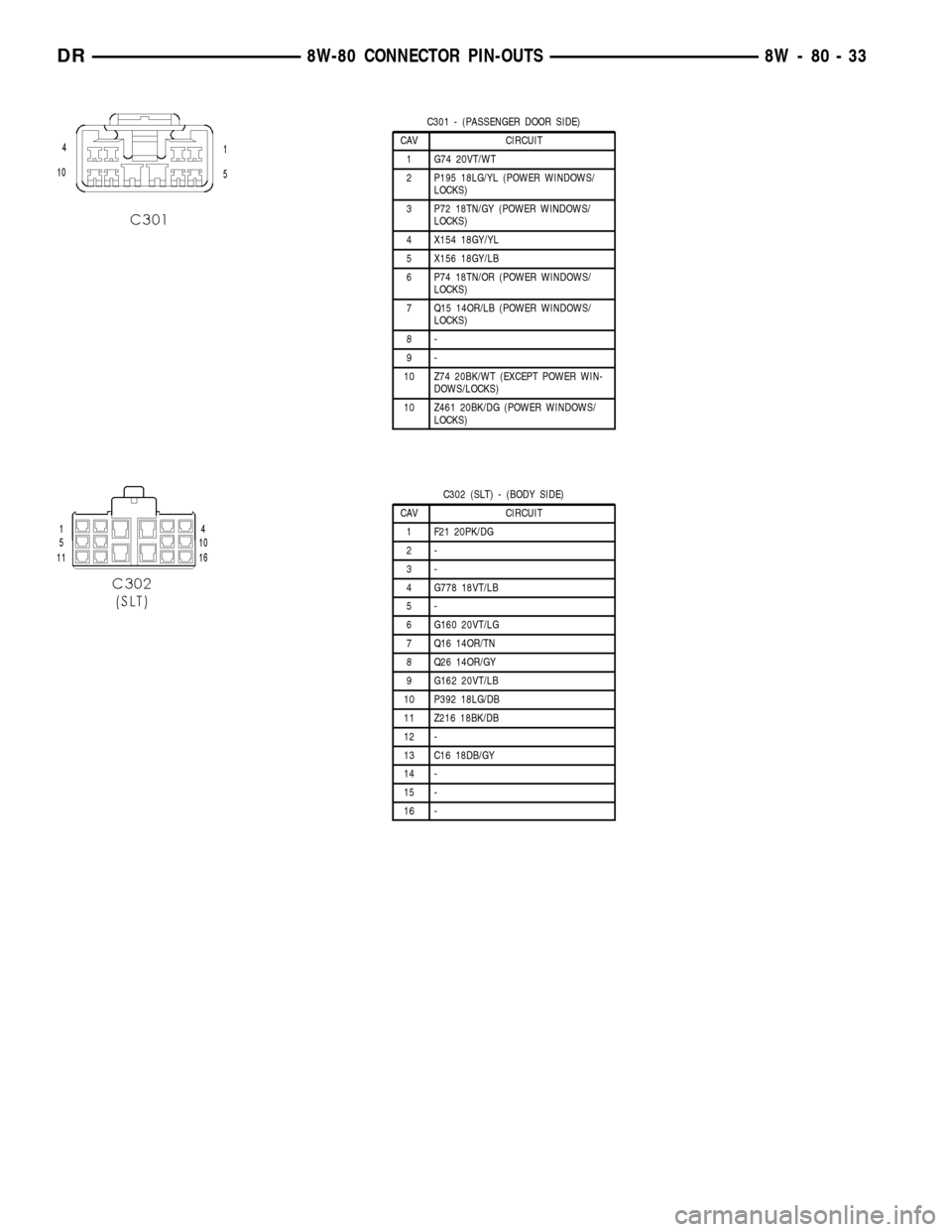
C301 - (PASSENGER DOOR SIDE)
CAV CIRCUIT
1 G74 20VT/WT
2 P195 18LG/YL (POWER WINDOWS/
LOCKS)
3 P72 18TN/GY (POWER WINDOWS/
LOCKS)
4 X154 18GY/YL
5 X156 18GY/LB
6 P74 18TN/OR (POWER WINDOWS/
LOCKS)
7 Q15 14OR/LB (POWER WINDOWS/
LOCKS)
8-
9-
10 Z74 20BK/WT (EXCEPT POWER WIN-
DOWS/LOCKS)
10 Z461 20BK/DG (POWER WINDOWS/
LOCKS)
C302 (SLT) - (BODY SIDE)
CAV CIRCUIT
1 F21 20PK/DG
2-
3-
4 G778 18VT/LB
5-
6 G160 20VT/LG
7 Q16 14OR/TN
8 Q26 14OR/GY
9 G162 20VT/LB
10 P392 18LG/DB
11 Z216 18BK/DB
12 -
13 C16 18DB/GY
14 -
15 -
16 -
DR8W-80 CONNECTOR PIN-OUTS 8W - 80 - 33
Page 1083 of 2627
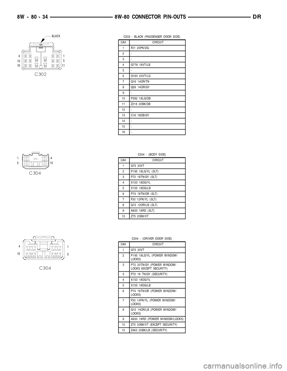
C302 - BLACK (PASSENGER DOOR SIDE)
CAV CIRCUIT
1 F21 20PK/DG
2-
3-
4 G778 18VT/LB
5-
6 G160 20VT/LG
7 Q16 14OR/TN
8 Q26 14OR/GY
9-
10 P392 18LG/DB
11 Z216 20BK/DB
12 -
13 C16 18DB/GY
14 -
15 -
16 -
C304 - (BODY SIDE)
CAV CIRCUIT
1 G75 20VT
2 P195 18LG/YL (SLT)
3 P72 18TN/GY (SLT)
4 X153 18DG/YL
5 X155 18DG/LB
6 P74 18TN/OR (SLT)
7 F30 12PK/YL (SLT)
8 Q15 12OR/LB (SLT)
9 A930 18RD (SLT)
10 Z75 20BK/VT
C304 - (DRIVER DOOR SIDE)
CAV CIRCUIT
1 G75 20VT
2 P195 18LG/YL (POWER WINDOW/
LOCKS)
3 P72 20TN/GY (POWER WINDOW/
LOCKS EXCEPT SECURITY)
3 P72 18 TN/GY (SECURITY)
4 X153 18DG/YL
5 X155 18DG/LB
6 P74 18TN/OR (POWER WINDOW/
LOCKS)
7 F30 14PK/YL (POWER WINDOW/
LOCKS)
8 Q15 14OR/LB (POWER WINDOW/
LOCKS)
9 A930 18RD (POWER WINDOW/LOCKS)
10 Z75 20BK/VT (EXCEPT SECURITY)
10 Z463 20BK/LB (SECURITY)
8W - 80 - 34 8W-80 CONNECTOR PIN-OUTSDR
Page 1089 of 2627
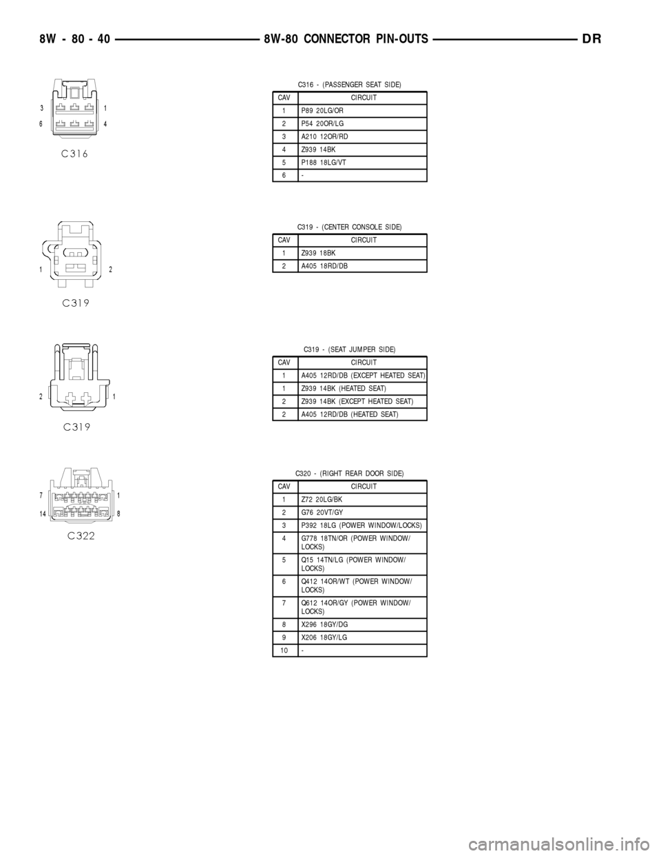
C316 - (PASSENGER SEAT SIDE)
CAV CIRCUIT
1 P89 20LG/OR
2 P54 20OR/LG
3 A210 12OR/RD
4 Z939 14BK
5 P188 18LG/VT
6-
C319 - (CENTER CONSOLE SIDE)
CAV CIRCUIT
1 Z939 18BK
2 A405 18RD/DB
C319 - (SEAT JUMPER SIDE)
CAV CIRCUIT
1 A405 12RD/DB (EXCEPT HEATED SEAT)
1 Z939 14BK (HEATED SEAT)
2 Z939 14BK (EXCEPT HEATED SEAT)
2 A405 12RD/DB (HEATED SEAT)
C320 - (RIGHT REAR DOOR SIDE)
CAV CIRCUIT
1 Z72 20LG/BK
2 G76 20VT/GY
3 P392 18LG (POWER WINDOW/LOCKS)
4 G778 18TN/OR (POWER WINDOW/
LOCKS)
5 Q15 14TN/LG (POWER WINDOW/
LOCKS)
6 Q412 14OR/WT (POWER WINDOW/
LOCKS)
7 Q612 14OR/GY (POWER WINDOW/
LOCKS)
8 X296 18GY/DG
9 X206 18GY/LG
10 -
8W - 80 - 40 8W-80 CONNECTOR PIN-OUTSDR
Page 1135 of 2627
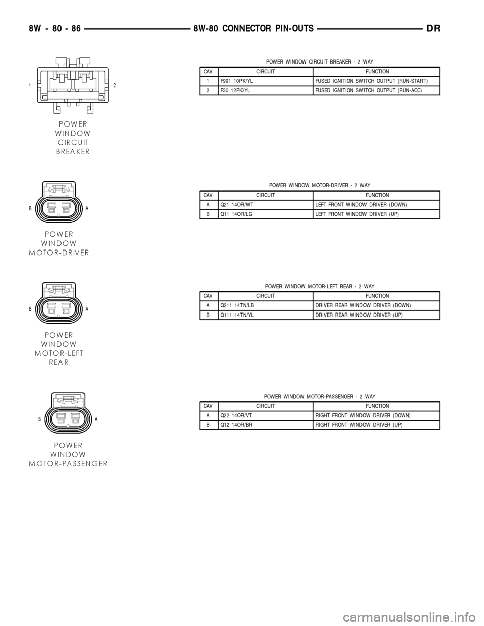
POWER WINDOW CIRCUIT BREAKER-2WAY
CAV CIRCUIT FUNCTION
1 F991 10PK/YL FUSED IGNITION SWITCH OUTPUT (RUN-START)
2 F30 12PK/YL FUSED IGNITION SWITCH OUTPUT (RUN-ACC)
POWER WINDOW MOTOR-DRIVER-2WAY
CAV CIRCUIT FUNCTION
A Q21 14OR/WT LEFT FRONT WINDOW DRIVER (DOWN)
B Q11 14OR/LG LEFT FRONT WINDOW DRIVER (UP)
POWER WINDOW MOTOR-LEFT REAR-2WAY
CAV CIRCUIT FUNCTION
A Q211 14TN/LB DRIVER REAR WINDOW DRIVER (DOWN)
B Q111 14TN/YL DRIVER REAR WINDOW DRIVER (UP)
POWER WINDOW MOTOR-PASSENGER-2WAY
CAV CIRCUIT FUNCTION
A Q22 14OR/VT RIGHT FRONT WINDOW DRIVER (DOWN)
B Q12 14OR/BR RIGHT FRONT WINDOW DRIVER (UP)
8W - 80 - 86 8W-80 CONNECTOR PIN-OUTSDR
Page 1136 of 2627
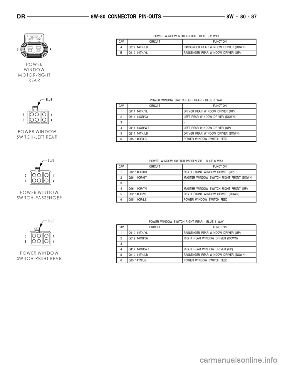
POWER WINDOW MOTOR-RIGHT REAR-2WAY
CAV CIRCUIT FUNCTION
A Q212 14TN/LB PASSENGER REAR WINDOW DRIVER (DOWN)
B Q112 14TN/YL PASSENGER REAR WINDOW DRIVER (UP)
POWER WINDOW SWITCH-LEFT REAR - BLUE 6 WAY
CAV CIRCUIT FUNCTION
1 Q111 14TN/YL DRIVER REAR WINDOW DRIVER (UP)
2 Q611 14OR/GY LEFT REAR WINDOW DRIVER (DOWN)
3- -
4 Q411 14OR/WT LEFT REAR WINDOW DRIVER (UP)
5 Q211 14TN/LB DRIVER REAR WINDOW DRIVER (DOWN)
6 Q15 14OR/LB POWER WINDOW SWITCH FEED
POWER WINDOW SWITCH-PASSENGER - BLUE 6 WAY
CAV CIRCUIT FUNCTION
1 Q12 14OR/BR RIGHT FRONT WINDOW DRIVER (UP)
2 Q26 14OR/GY MASTER WINDOW SWITCH RIGHT FRONT (DOWN)
3- -
4 Q16 14OR/TN MASTER WINDOW SWITCH RIGHT FRONT (UP)
5 Q22 14OR/VT RIGHT FRONT WINDOW DRIVER (DOWN)
6 Q15 14OR/LB POWER WINDOW SWITCH FEED
POWER WINDOW SWITCH-RIGHT REAR - BLUE 6 WAY
CAV CIRCUIT FUNCTION
1 Q112 14TN/YL PASSENGER REAR WINDOW DRIVER (UP)
2 Q612 14OR/GY RIGHT REAR WINDOW DRIVER (DOWN)
3- -
4 Q412 14OR/WT RIGHT REAR WINDOW DRIVER (UP)
5 Q212 14TN/LB PASSENGER REAR WINDOW DRIVER (DOWN)
6 Q15 14TN/LG POWER WINDOW SWITCH FEED
DR8W-80 CONNECTOR PIN-OUTS 8W - 80 - 87
Page 1159 of 2627
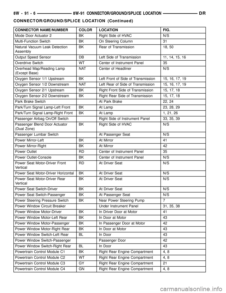
CONNECTOR NAME/NUMBER COLOR LOCATION FIG.
Mode Door Actuator 2 BK Right Side of HVAC N/S
Multi-Function Switch BK On Steering Column 31
Natural Vacuum Leak Detection
AssemblyBK Rear of Transmission 18, 50
Output Speed Sensor DB Left Side of Transmission 11, 14, 15, 16
Overdrive Switch WT Center of Instrument Panel 35
Overhead Map/Reading Lamp
(Except Base)NAT Center of Headliner N/S
Oxygen Sensor 1/1 Upstream BK Left Front of Side of Transmission 15, 16, 17, 19
Oxygen Sensor 1/2 Downstream NAT Left Rear of Side of Transmission 15, 16, 17, 19
Oxygen Sensor 2/1 Upstream BK Right Front Side of Transmission 15, 17, 18
Oxygen Sensor 2/2 Downstream BK Right Rear Side of Transmission 15, 17, 18
Park Brake Switch At Park Brake 22, 24
Park/Turn Signal Lamp-Left Front BK At Lamp 23, 28, 29
Park/Turn Signal Lamp-Right Front BK At Lamp 1, 21, 26
Passenger Airbag On/Off Switch Right Side of Instrument Panel 33, 35, 39
Passenger Blend Door Actuator
(Dual Zone)BK Right Side of HVAC N/S
Passenger Lumbar Switch At Passenger Seat N/S
Power Mirror-Left BK At Mirror 41
Power Mirror-Right BK At Mirror 42
Power Outlet RD Center of Instrument Panel 35
Power Outlet-Console BK Center of Instrument Panel N/S
Power Seat Motor-Driver Front
VerticalRD At Driver Seat N/S
Power Seat Motor-Driver Horizontal BK At Driver Seat N/S
Power Seat Motor-Driver Rear
VerticalBK At Driver Seat N/S
Power Seat Switch-Driver BK At Driver Seat N/S
Power Seat Switch-Passenger BK At Passenger Seat N/S
Power Steering Pressure Switch BK Near Power Steering Pump 7
Power Window Circuit Breaker Under Instrument Panel 31, 35, 38
Power Window Motor-Driver BK In Driver Door at Motor 41
Power Window Motor-Left Rear BK In Door at Motor 43
Power Window Motor-Passenger BK In Passenger Door at Motor 42
Power Window Motor-Right Rear BK In Door at Motor 43
Power Window Switch-Left Rear BL In Door 43
Power Window Switch-Passenger Passenger Door 42
Power Window Switch-Right Rear BL In Door 43
Powertrain Control Module C1 BK Right Rear Engine Compartment 4, 8
Powertrain Control Module C2 WT Right Rear Engine Compartment 4, 8
Powertrain Control Module C3 GY Right Rear Engine Compartment 21
Powertrain Control Module C4 GN Right Rear Engine Compartment 4, 8
8W - 91 - 6 8W-91 CONNECTOR/GROUND/SPLICE LOCATIONDR
CONNECTOR/GROUND/SPLICE LOCATION (Continued)
Page 2297 of 2627

VISUAL INSPECTION BEFORE WATER LEAK TESTS
Verify that floor and body plugs are in place, body
drains are clear, and body components are properly
aligned and sealed. If component alignment or seal-
ing is necessary, refer to the appropriate section of
this group for proper procedures.
WATER LEAK TESTS
WARNING: DO NOT USE ELECTRIC SHOP LIGHTS
OR TOOLS IN WATER TEST AREA. PERSONAL
INJURY CAN RESULT.
When the conditions causing a water leak have
been determined, simulate the conditions as closely
as possible.
²If a leak occurs with the vehicle parked in a
steady light rain, flood the leak area with an open-
ended garden hose.
²If a leak occurs while driving at highway speeds
in a steady rain, test the leak area with a reasonable
velocity stream or fan spray of water. Direct the
spray in a direction comparable to actual conditions.
²If a leak occurs when the vehicle is parked on an
incline, hoist the end or side of the vehicle to simu-
late this condition. This method can be used when
the leak occurs when the vehicle accelerates, stops or
turns. If the leak occurs on acceleration, hoist the
front of the vehicle. If the leak occurs when braking,
hoist the back of the vehicle. If the leak occurs on left
turns, hoist the left side of the vehicle. If the leak
occurs on right turns, hoist the right side of the vehi-
cle. For hoisting recommendations (Refer to LUBRI-
CATION & MAINTENANCE/HOISTING -
STANDARD PROCEDURE).
WATER LEAK DETECTION
To detect a water leak point-of-entry, do a water
test and watch for water tracks or droplets forming
on the inside of the vehicle. If necessary, remove inte-
rior trim covers or panels to gain visual access to the
leak area. If the hose cannot be positioned without
being held, have someone help do the water test.
Some water leaks must be tested for a considerable
length of time to become apparent. When a leak
appears, find the highest point of the water track or
drop. The highest point usually will show the point of
entry. After leak point has been found, repair the
leak and water test to verify that the leak has
stopped.
Locating the entry point of water that is leaking
into a cavity between panels can be difficult. The
trapped water may splash or run from the cavity,
often at a distance from the entry point. Most water
leaks of this type become apparent after accelerating,
stopping, turning, or when on an incline.MIRROR INSPECTION METHOD
When a leak point area is visually obstructed, use
a suitable mirror to gain visual access. A mirror can
also be used to deflect light to a limited-access area
to assist in locating a leak point.
BRIGHT LIGHT LEAK TEST METHOD
Some water leaks in the luggage compartment can
be detected without water testing. Position the vehi-
cle in a brightly lit area. From inside the darkened
luggage compartment inspect around seals and body
seams. If necessary, have a helper direct a drop light
over the suspected leak areas around the luggage
compartment. If light is visible through a normally
sealed location, water could enter through the open-
ing.
PRESSURIZED LEAK TEST METHOD
When a water leak into the passenger compart-
ment cannot be detected by water testing, pressurize
the passenger compartment and soap test exterior of
the vehicle. To pressurize the passenger compart-
ment, close all doors and windows, start engine, and
set heater control to high blower in HEAT position. If
engine can not be started, connect a charger to the
battery to ensure adequate voltage to the blower.
With interior pressurized, apply dish detergent solu-
tion to suspected leak area on the exterior of the
vehicle. Apply detergent solution with spray device or
soft bristle brush. If soap bubbles occur at a body
seam, joint, seal or gasket, the leak entry point could
be at that location.
DIAGNOSIS AND TESTING - WIND NOISE
Wind noise is the result of most air leaks. Air leaks
can be caused by poor sealing, improper body compo-
nent alignment, body seam porosity, or missing plugs
in the engine compartment or door hinge pillar areas.
All body sealing points should be airtight in normal
driving conditions. Moving sealing surfaces will not
always seal airtight under all conditions. At times,
side glass or door seals will allow wind noise to be
noticed in the passenger compartment during high
cross winds. Over compensating on door or glass
adjustments to stop wind noise that occurs under
severe conditions can cause premature seal wear and
excessive closing or latching effort. After a repair pro-
cedure has been performed, test vehicle to verify
noise has stopped before returning vehicle to use.
VISUAL INSPECTION BEFORE TESTS
Verify that floor and body plugs are in place and
body components are aligned and sealed. If compo-
nent alignment or sealing is necessary, refer to the
appropriate section of this group for proper proce-
dures.
23 - 2 BODYDR
BODY (Continued)
Page 2488 of 2627

HEATING & AIR CONDITIONING
TABLE OF CONTENTS
page page
HEATING & AIR CONDITIONING
DESCRIPTION
DESCRIPTION - ENGINE COOLING
SYSTEM REQUIREMENTS...............1
DESCRIPTION - HEATER AND AIR
CONDITIONER........................1
OPERATION - HEATER AND AIR
CONDITIONER........................1
DIAGNOSIS AND TESTING
DIAGNOSIS AND TESTING - A/C
PERFORMANCE.......................3DIAGNOSIS AND TESTING - HEATER
PERFORMANCE TEST..................6
SPECIFICATIONS - A/C SYSTEM............7
CONTROLS.............................9
DISTRIBUTION..........................26
PLUMBING.............................41
HEATING & AIR
CONDITIONING
DESCRIPTION
DESCRIPTION - ENGINE COOLING SYSTEM
REQUIREMENTS
To maintain the performance level of the heating,
ventilation and air conditioning (HVAC) system, the
engine cooling system must be properly maintained.
The use of a bug screen is not recommended. Any
obstructions in front of the radiator or A/C condenser
will reduce the performance of the A/C and engine
cooling systems.
The engine cooling system includes the radiator,
thermostat, radiator hoses and the engine coolant
pump. Refer to Cooling for more information before
opening or attempting any service to the engine cool-
ing system.
DESCRIPTION - HEATER AND AIR
CONDITIONER
A manually controlled single zone type heating-air
conditioning system or a manually controlled dual
zone type heating-air conditioning system is available
on this model.
All vehicles are equipped with a common heater,
ventilation and air conditioning (HVAC) housing (Fig.
1). The system combines air conditioning, heating,
and ventilating capabilities in a single unit housing
mounted within the passenger compartment under
the instrument panel. The HVAC housing includes:
²Blower motor
²Blower motor resistor block²Heater core
²Evaporator coil
²Blend door and actuator
²Defrost door and actuator
²Mode door and actuator
²Recirculation door and actuator
Based upon the system and mode selected, condi-
tioned air can exit the HVAC housing through one or
a combination of the three main housing outlets:
defrost, panel or floor. The defrost outlet is located on
the top of the housing, the panel outlet is located on
the face of the housing and the floor outlet is located
on the bottom of the housing. Once the conditioned
air exits the unit housing, it is further directed
through molded plastic ducts to the various outlets in
the vehicle interior. These outlets and their locations
are as follows:
²Defroster Outlet- A single large defroster out-
let is located in the center of the instrument panel
top cover, near the base of the windshield.
²Side Window Demister Outlets- There are
two side window demister outlets, one is located at
each outboard end of the instrument panel top cover,
near the belt line at the A-pillars.
²Panel Outlets- There are four panel outlets in
the instrument panel, one located near each outboard
end of the instrument panel facing the rear of the
vehicle and two located near the top of the instru-
ment panel center bezel.
²Front Floor Outlets- There are two front floor
outlets, one located above each side of the floor panel
center tunnel near the dash panel.
OPERATION - HEATER AND AIR CONDITIONER
The heating and air conditioning systems pulls
outside (ambient) air through the cowl opening at the
base of the windshield, then into the plenum cham-
DRHEATING & AIR CONDITIONING 24 - 1