1998 DODGE RAM 1500 cluster
[x] Cancel search: clusterPage 1052 of 2627
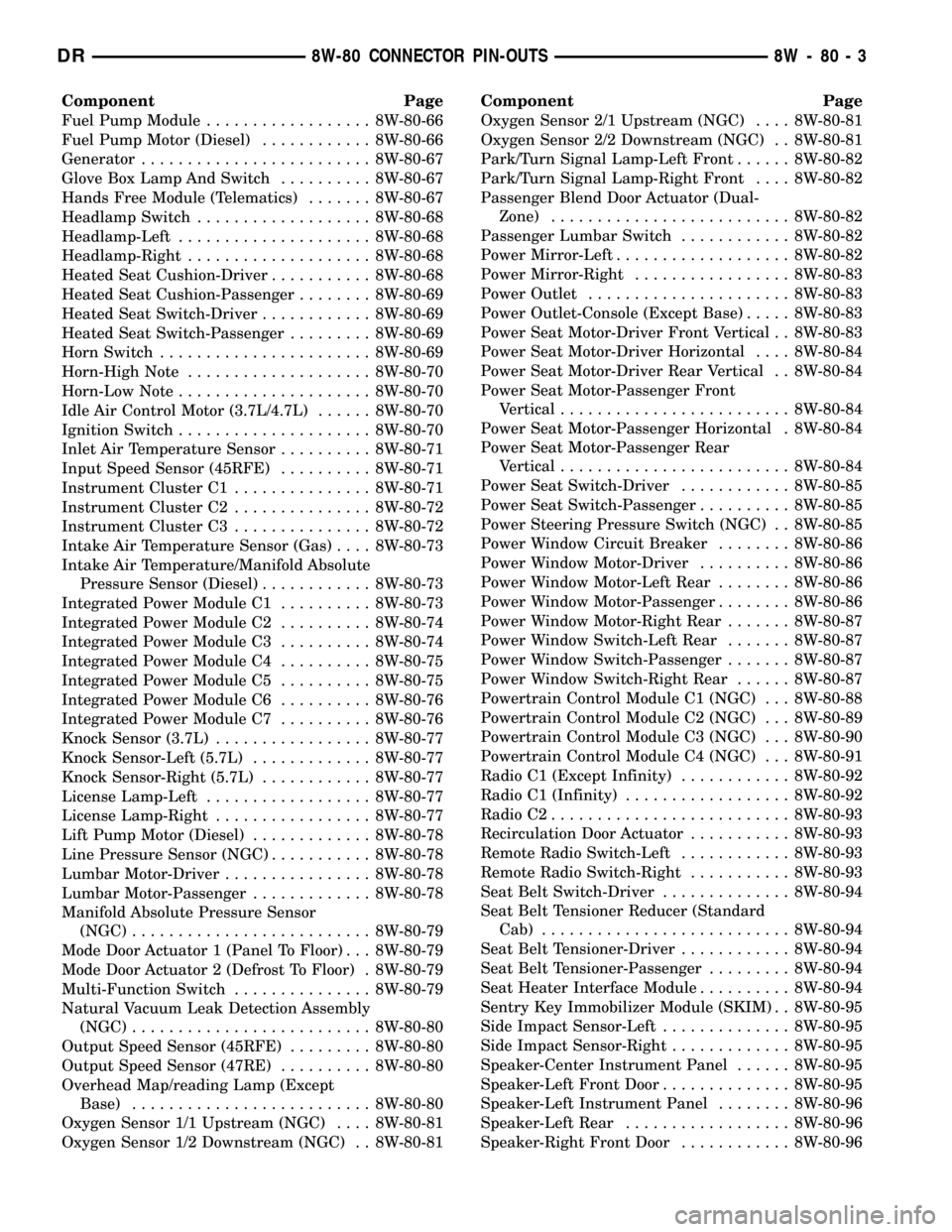
Component Page
Fuel Pump Module.................. 8W-80-66
Fuel Pump Motor (Diesel)............ 8W-80-66
Generator......................... 8W-80-67
Glove Box Lamp And Switch.......... 8W-80-67
Hands Free Module (Telematics)....... 8W-80-67
Headlamp Switch................... 8W-80-68
Headlamp-Left..................... 8W-80-68
Headlamp-Right.................... 8W-80-68
Heated Seat Cushion-Driver........... 8W-80-68
Heated Seat Cushion-Passenger........ 8W-80-69
Heated Seat Switch-Driver............ 8W-80-69
Heated Seat Switch-Passenger......... 8W-80-69
Horn Switch....................... 8W-80-69
Horn-High Note.................... 8W-80-70
Horn-Low Note..................... 8W-80-70
Idle Air Control Motor (3.7L/4.7L)...... 8W-80-70
Ignition Switch..................... 8W-80-70
Inlet Air Temperature Sensor.......... 8W-80-71
Input Speed Sensor (45RFE).......... 8W-80-71
Instrument Cluster C1............... 8W-80-71
Instrument Cluster C2............... 8W-80-72
Instrument Cluster C3............... 8W-80-72
Intake Air Temperature Sensor (Gas).... 8W-80-73
Intake Air Temperature/Manifold Absolute
Pressure Sensor (Diesel)............ 8W-80-73
Integrated Power Module C1.......... 8W-80-73
Integrated Power Module C2.......... 8W-80-74
Integrated Power Module C3.......... 8W-80-74
Integrated Power Module C4.......... 8W-80-75
Integrated Power Module C5.......... 8W-80-75
Integrated Power Module C6.......... 8W-80-76
Integrated Power Module C7.......... 8W-80-76
Knock Sensor (3.7L)................. 8W-80-77
Knock Sensor-Left (5.7L)............. 8W-80-77
Knock Sensor-Right (5.7L)............ 8W-80-77
License Lamp-Left.................. 8W-80-77
License Lamp-Right................. 8W-80-77
Lift Pump Motor (Diesel)............. 8W-80-78
Line Pressure Sensor (NGC)........... 8W-80-78
Lumbar Motor-Driver................ 8W-80-78
Lumbar Motor-Passenger............. 8W-80-78
Manifold Absolute Pressure Sensor
(NGC).......................... 8W-80-79
Mode Door Actuator 1 (Panel To Floor) . . . 8W-80-79
Mode Door Actuator 2 (Defrost To Floor) . 8W-80-79
Multi-Function Switch............... 8W-80-79
Natural Vacuum Leak Detection Assembly
(NGC).......................... 8W-80-80
Output Speed Sensor (45RFE)......... 8W-80-80
Output Speed Sensor (47RE).......... 8W-80-80
Overhead Map/reading Lamp (Except
Base).......................... 8W-80-80
Oxygen Sensor 1/1 Upstream (NGC).... 8W-80-81
Oxygen Sensor 1/2 Downstream (NGC) . . 8W-80-81Component Page
Oxygen Sensor 2/1 Upstream (NGC).... 8W-80-81
Oxygen Sensor 2/2 Downstream (NGC) . . 8W-80-81
Park/Turn Signal Lamp-Left Front...... 8W-80-82
Park/Turn Signal Lamp-Right Front.... 8W-80-82
Passenger Blend Door Actuator (Dual-
Zone).......................... 8W-80-82
Passenger Lumbar Switch............ 8W-80-82
Power Mirror-Left................... 8W-80-82
Power Mirror-Right................. 8W-80-83
Power Outlet...................... 8W-80-83
Power Outlet-Console (Except Base)..... 8W-80-83
Power Seat Motor-Driver Front Vertical . . 8W-80-83
Power Seat Motor-Driver Horizontal.... 8W-80-84
Power Seat Motor-Driver Rear Vertical . . 8W-80-84
Power Seat Motor-Passenger Front
Vertical......................... 8W-80-84
Power Seat Motor-Passenger Horizontal . 8W-80-84
Power Seat Motor-Passenger Rear
Vertical......................... 8W-80-84
Power Seat Switch-Driver............ 8W-80-85
Power Seat Switch-Passenger.......... 8W-80-85
Power Steering Pressure Switch (NGC) . . 8W-80-85
Power Window Circuit Breaker........ 8W-80-86
Power Window Motor-Driver.......... 8W-80-86
Power Window Motor-Left Rear........ 8W-80-86
Power Window Motor-Passenger........ 8W-80-86
Power Window Motor-Right Rear....... 8W-80-87
Power Window Switch-Left Rear....... 8W-80-87
Power Window Switch-Passenger....... 8W-80-87
Power Window Switch-Right Rear...... 8W-80-87
Powertrain Control Module C1 (NGC) . . . 8W-80-88
Powertrain Control Module C2 (NGC) . . . 8W-80-89
Powertrain Control Module C3 (NGC) . . . 8W-80-90
Powertrain Control Module C4 (NGC) . . . 8W-80-91
Radio C1 (Except Infinity)............ 8W-80-92
Radio C1 (Infinity).................. 8W-80-92
Radio C2.......................... 8W-80-93
Recirculation Door Actuator........... 8W-80-93
Remote Radio Switch-Left............ 8W-80-93
Remote Radio Switch-Right........... 8W-80-93
Seat Belt Switch-Driver.............. 8W-80-94
Seat Belt Tensioner Reducer (Standard
Cab)........................... 8W-80-94
Seat Belt Tensioner-Driver............ 8W-80-94
Seat Belt Tensioner-Passenger......... 8W-80-94
Seat Heater Interface Module.......... 8W-80-94
Sentry Key Immobilizer Module (SKIM) . . 8W-80-95
Side Impact Sensor-Left.............. 8W-80-95
Side Impact Sensor-Right............. 8W-80-95
Speaker-Center Instrument Panel...... 8W-80-95
Speaker-Left Front Door.............. 8W-80-95
Speaker-Left Instrument Panel........ 8W-80-96
Speaker-Left Rear.................. 8W-80-96
Speaker-Right Front Door............ 8W-80-96
DR8W-80 CONNECTOR PIN-OUTS 8W - 80 - 3
Page 1120 of 2627
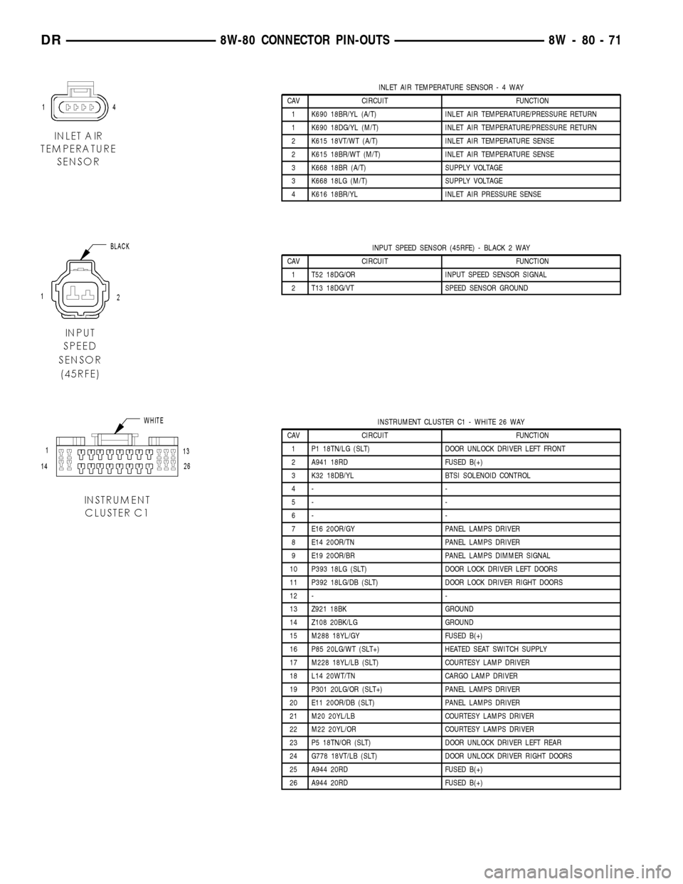
INLET AIR TEMPERATURE SENSOR-4WAY
CAV CIRCUIT FUNCTION
1 K690 18BR/YL (A/T) INLET AIR TEMPERATURE/PRESSURE RETURN
1 K690 18DG/YL (M/T) INLET AIR TEMPERATURE/PRESSURE RETURN
2 K615 18VT/WT (A/T) INLET AIR TEMPERATURE SENSE
2 K615 18BR/WT (M/T) INLET AIR TEMPERATURE SENSE
3 K668 18BR (A/T) SUPPLY VOLTAGE
3 K668 18LG (M/T) SUPPLY VOLTAGE
4 K616 18BR/YL INLET AIR PRESSURE SENSE
INPUT SPEED SENSOR (45RFE) - BLACK 2 WAY
CAV CIRCUIT FUNCTION
1 T52 18DG/OR INPUT SPEED SENSOR SIGNAL
2 T13 18DG/VT SPEED SENSOR GROUND
INSTRUMENT CLUSTER C1 - WHITE 26 WAY
CAV CIRCUIT FUNCTION
1 P1 18TN/LG (SLT) DOOR UNLOCK DRIVER LEFT FRONT
2 A941 18RD FUSED B(+)
3 K32 18DB/YL BTSI SOLENOID CONTROL
4- -
5- -
6- -
7 E16 20OR/GY PANEL LAMPS DRIVER
8 E14 20OR/TN PANEL LAMPS DRIVER
9 E19 20OR/BR PANEL LAMPS DIMMER SIGNAL
10 P393 18LG (SLT) DOOR LOCK DRIVER LEFT DOORS
11 P392 18LG/DB (SLT) DOOR LOCK DRIVER RIGHT DOORS
12 - -
13 Z921 18BK GROUND
14 Z108 20BK/LG GROUND
15 M288 18YL/GY FUSED B(+)
16 P85 20LG/WT (SLT+) HEATED SEAT SWITCH SUPPLY
17 M228 18YL/LB (SLT) COURTESY LAMP DRIVER
18 L14 20WT/TN CARGO LAMP DRIVER
19 P301 20LG/OR (SLT+) PANEL LAMPS DRIVER
20 E11 20OR/DB (SLT) PANEL LAMPS DRIVER
21 M20 20YL/LB COURTESY LAMPS DRIVER
22 M22 20YL/OR COURTESY LAMPS DRIVER
23 P5 18TN/OR (SLT) DOOR UNLOCK DRIVER LEFT REAR
24 G778 18VT/LB (SLT) DOOR UNLOCK DRIVER RIGHT DOORS
25 A944 20RD FUSED B(+)
26 A944 20RD FUSED B(+)
DR8W-80 CONNECTOR PIN-OUTS 8W - 80 - 71
Page 1121 of 2627
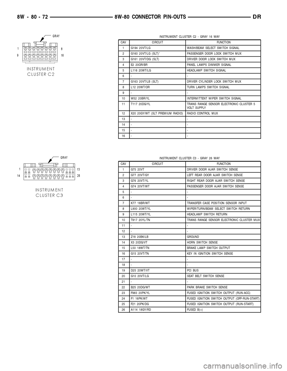
INSTRUMENT CLUSTER C2 - GRAY 16 WAY
CAV CIRCUIT FUNCTION
1 G194 20VT/LG WASH/BEAM SELECT SWITCH SIGNAL
2 G160 20VT/LG (SLT)8PASSENGER DOOR LOCK SWITCH MUX
3 G161 20VT/DG (SLT) DRIVER DOOR LOCK SWITCH MUX
4 E2 20OR/BR PANEL LAMPS DIMMER SIGNAL
5 L116 20WT/LG HEADLAMP SWITCH SIGNAL
6- -
7 G163 20VT/LB (SLT) DRIVER CYLINDER LOCK SWITCH MUX
8 L12 20WT/OR TURN LAMPS SWITCH SIGNAL
9- -
10 W52 20BR/YL INTERMITTENT WIPER SWITCH SIGNAL
11 T117 20DG/YL TRANS RANGE SENSOR ELECTRONIC CLUSTER 5
VOLT SUPPLY
12 X20 20GY/WT (SLT PREMIUM RADIO) RADIO CONTROL MUX
13 - -
14 - -
15 - -
16 - -
INSTRUMENT CLUSTER C3 - GRAY 26 WAY
CAV CIRCUIT FUNCTION
1 G75 20VT DRIVER DOOR AJAR SWITCH SENSE
2 G77 20VT/GY LEFT REAR DOOR AJAR SWITCH SENSE
3 G76 20VT/YL RIGHT REAR DOOR AJAR SWITCH SENSE
4 G74 20VT/WT PASSENGER DOOR AJAR SWITCH SENSE
5- -
6- -
7 K77 18BR/WT TRANSFER CASE POSITION SENSOR INPUT
8 L900 20WT/YL WIPER/TURN/BEAM SELECT SWITCH RETURN
9 L115 20WT/YL HEADLAMP SWITCH RETURN
10 T917 20YL/TN TRANS RANGE SENSOR ELECTRONIC CLUSTER MUX
11 - -
12 - -
13 Z18 20BK/LB GROUND
14 X3 20DG/VT HORN SWITCH SENSE
15 L50 18WT/TN BRAKE LAMP SWITCH OUTPUT
16 G15 20VT/TN KEY IN IGNITION SWITCH SENSE
17 - -
18 - -
19 D25 20WT/VT PCI BUS
20 G10 20VT/LG SEAT BELT SWITCH SENSE
21 - -
22 B25 20DG/WT PARK BRAKE SWITCH SENSE
23 F983 20PK/YL FUSED IGNITION SWITCH OUTPUT (RUN-ACC)
24 F1 16PK/WT FUSED IGNITION SWITCH OUTPUT (OFF-RUN-START)
25 F21 20PK/DG FUSED IGNITION SWITCH OUTPUT (RUN-START)
26 A114 18GY/RD FUSED B(+)
8W - 80 - 72 8W-80 CONNECTOR PIN-OUTSDR
Page 1151 of 2627
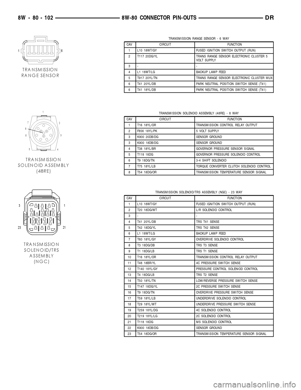
TRANSMISSION RANGE SENSOR-6WAY
CAV CIRCUIT FUNCTION
1 L10 18WT/GY FUSED IGNITION SWITCH OUTPUT (RUN)
2 T117 20DG/YL TRANS RANGE SENSOR ELECTRONIC CLUSTER 5
VOLT SUPPLY
3- -
4 L1 18WT/LG BACKUP LAMP FEED
5 T917 20YL/TN TRANS RANGE SENSOR ELECTRONIC CLUSTER MUX
6 T41 20YL/DB PARK NEUTRAL POSITION SWITCH SENSE (T41)
6 T41 18YL/DB PARK NEUTRAL POSITION SWITCH SENSE (T41)
TRANSMISSION SOLENOID ASSEMBLY (48RE)-8WAY
CAV CIRCUIT FUNCTION
1 T16 18YL/OR TRANSMISSION CONTROL RELAY OUTPUT
2 F856 18YL/PK 5 VOLT SUPPLY
3 K900 20DB/DG SENSOR GROUND
3 K900 18DB/DG SENSOR GROUND
4 T38 18YL/BR GOVERNOR PRESSURE SENSOR SIGNAL
5 T118 18DG GOVERNOR PRESSURE SOLENOID CONTROL
6 T9 18DG/TN 3-4 SHIFT SOLENOID
7 T75 18YL/LB TORQUE CONVERTER CLUTCH SOLENOID CONTROL
8 T54 18DG/OR TRANSMISSION TEMPERATURE SENSOR SIGNAL
TRANSMISSION SOLENOID/TRS ASSEMBLY (NGC) - 23 WAY
CAV CIRCUIT FUNCTION
1 L10 18WT/GY FUSED IGNITION SWITCH OUTPUT (RUN)
2 T20 18DG/WT L/R SOLENOID CONTROL
3- -
4 T41 20YL/DB TRS T41 SENSE
5 T42 18DG/YL TRS T42 SENSE
6 L1 18WT/LG BACKUP LAMP FEED
7 T60 18YL/GY OVERDRIVE SOLENOID CONTROL
8 T3 18DG/DB TRS T3 SENSE
9 T1 18DG/LB TRS T1 SENSE
10 T16 18YL/OR TRANSMISSION CONTROL RELAY OUTPUT
11 T48 18BR/YL 4C PRESSURE SWITCH SENSE
12 T140 18YL/GY PRESSURE CONTROL SOLENIOD CONTROL
13 T4 18DG/LB TRS T2 SENSE
14 T50 18YL/TN LOW/REVERSE PRESSURE SWITCH SENSE
15 T147 18DG/YL 2C PRESSURE SWITCH SENSE
16 T9 18DG/TN OVERDRIVE PRESSURE SWITCH SENSE
17 T59 18YL/LB UNDERDRIVE SOLENOID CONTROL
18 T29 18YL/WT UNDERDRIVE PRESSURE SWITCH SENSE
19 T259 18YL/DG 4C SOLENOID CONTROL
20 T219 18YL/LG 2C SOLENOID CONTROL
21 T118 18DG MS SOLENOID CONTROL
22 K900 18DB/DG SENSOR GROUND
23 T54 18DG/OR TRANSMISSION TEMPERATURE SENSOR SIGNAL
8W - 80 - 102 8W-80 CONNECTOR PIN-OUTSDR
Page 1158 of 2627
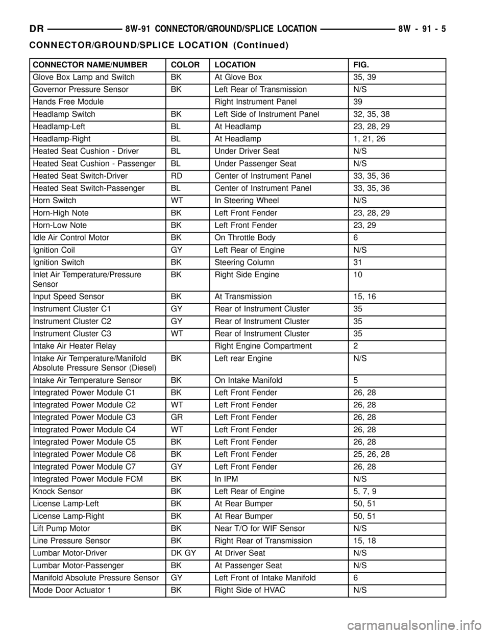
CONNECTOR NAME/NUMBER COLOR LOCATION FIG.
Glove Box Lamp and Switch BK At Glove Box 35, 39
Governor Pressure Sensor BK Left Rear of Transmission N/S
Hands Free Module Right Instrument Panel 39
Headlamp Switch BK Left Side of Instrument Panel 32, 35, 38
Headlamp-Left BL At Headlamp 23, 28, 29
Headlamp-Right BL At Headlamp 1, 21, 26
Heated Seat Cushion - Driver BL Under Driver Seat N/S
Heated Seat Cushion - Passenger BL Under Passenger Seat N/S
Heated Seat Switch-Driver RD Center of Instrument Panel 33, 35, 36
Heated Seat Switch-Passenger BL Center of Instrument Panel 33, 35, 36
Horn Switch WT In Steering Wheel N/S
Horn-High Note BK Left Front Fender 23, 28, 29
Horn-Low Note BK Left Front Fender 23, 29
Idle Air Control Motor BK On Throttle Body 6
Ignition Coil GY Left Rear of Engine N/S
Ignition Switch BK Steering Column 31
Inlet Air Temperature/Pressure
SensorBK Right Side Engine 10
Input Speed Sensor BK At Transmission 15, 16
Instrument Cluster C1 GY Rear of Instrument Cluster 35
Instrument Cluster C2 GY Rear of Instrument Cluster 35
Instrument Cluster C3 WT Rear of Instrument Cluster 35
Intake Air Heater Relay Right Engine Compartment 2
Intake Air Temperature/Manifold
Absolute Pressure Sensor (Diesel)BK Left rear Engine N/S
Intake Air Temperature Sensor BK On Intake Manifold 5
Integrated Power Module C1 BK Left Front Fender 26, 28
Integrated Power Module C2 WT Left Front Fender 26, 28
Integrated Power Module C3 GR Left Front Fender 26, 28
Integrated Power Module C4 WT Left Front Fender 26, 28
Integrated Power Module C5 BK Left Front Fender 26, 28
Integrated Power Module C6 BK Left Front Fender 25, 26, 28
Integrated Power Module C7 GY Left Front Fender 26, 28
Integrated Power Module FCM BK In IPM N/S
Knock Sensor BK Left Rear of Engine 5, 7, 9
License Lamp-Left BK At Rear Bumper 50, 51
License Lamp-Right BK At Rear Bumper 50, 51
Lift Pump Motor BK Near T/O for WIF Sensor N/S
Line Pressure Sensor BK Right Rear of Transmission 15, 18
Lumbar Motor-Driver DK GY At Driver Seat N/S
Lumbar Motor-Passenger BK At Passenger Seat N/S
Manifold Absolute Pressure Sensor GY Left Front of Intake Manifold 6
Mode Door Actuator 1 BK Right Side of HVAC N/S
DR8W-91 CONNECTOR/GROUND/SPLICE LOCATION 8W - 91 - 5
CONNECTOR/GROUND/SPLICE LOCATION (Continued)
Page 1221 of 2627
requires the use of a DRB IIItscan tool and the
proper Body Diagnostic Procedures manual.
Before any testing of the front control module is
attempted, the battery should be fully charged and
all wire harness and ground connections inspected
around the affected areas on the vehicle.
REMOVAL
(1) Disconnect the positive and negative battery
cables from the battery.
(2) Partially remove the integrated power module
from the engine compartment (Refer to 8 - ELECTRI-
CAL/POWER DISTRIBUTION/INTEGRATED
POWER MODULE - REMOVAL).
(3) Remove the front control module retaining
screws.
(4) Using both hands, pull the front control module
straightfrom the integrated power module assembly
to disconnect the 49-way electrical connector and
remove the front control module from the vehicle.
INSTALLATION
(1) Install the front control module on the inte-
grated power module assembly by pushing the
49-way electrical connector straight in.
(2) Install the front control module retaining
screws. Torque the screws to 7 in. lbs.
(3) Install the integrated power module (Refer to 8
- ELECTRICAL/POWER DISTRIBUTION/INTE-
GRATED POWER MODULE - INSTALLATION).
(4) Connect the positive and negative battery
cables.
IOD FUSE
DESCRIPTION
All vehicles are equipped with an Ignition-Off
Draw (IOD) fuse that is disconnected within the Inte-
grated Power Module when the vehicle is shipped
from the factory. Dealer personnel are to reconnect
the IOD fuse in the Integrated Power Module as part
of the preparation procedures performed just prior to
new vehicle delivery.
A laser printed fuse layout map is integral to the
Integrated Power Module cover to ensure proper fuse
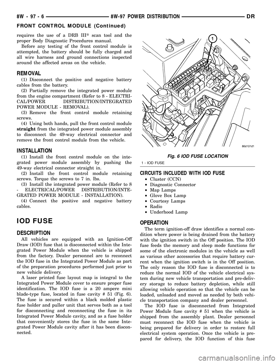
identification. The IOD fuse is a 20 ampere mini
blade-type fuse, located in fuse cavity # 51 (Fig. 6).
The fuse is secured within a black molded plastic
fuse holder and puller unit that serves both as a tool
for disconnecting and reconnecting the fuse in its
Integrated Power Module cavity, and as a fuse holder
that conveniently stores the fuse in the same Inte-
grated Power Module cavity after it has been discon-
nected.
CIRCUITS INCLUDED WITH IOD FUSE
²Cluster (CCN)
²Diagnostic Connector
²Map Lamps
²Glove Box Lamp
²Courtesy Lamps
²Radio
²Underhood Lamp
OPERATION
The term ignition-off draw identifies a normal con-
dition where power is being drained from the battery
with the ignition switch in the Off position. The IOD
fuse feeds the memory and sleep mode functions for
some of the electronic modules in the vehicle as well
as various other accessories that require battery cur-
rent when the ignition switch is in the Off position.
The only reason the IOD fuse is disconnected is to
reduce the normal IOD of the vehicle electrical sys-
tem during new vehicle transportation and pre-deliv-
ery storage to reduce battery depletion, while still
allowing vehicle operation so that the vehicle can be
loaded, unloaded and moved as needed by both vehi-
cle transportation company and dealer personnel.
The IOD fuse is disconnected from Integrated
Power Module fuse cavity # 51 when the vehicle is
shipped from the assembly plant. Dealer personnel
must reconnect the IOD fuse when the vehicle is
being prepared for delivery in order to restore full
electrical system operation. Once the vehicle is pre-
pared for delivery, the IOD function of this fuse
Fig. 6 IOD FUSE LOCATION
1 - IOD FUSE
8W - 97 - 6 8W-97 POWER DISTRIBUTIONDR
FRONT CONTROL MODULE (Continued)
Page 1575 of 2627
OPERATION
Fuel Pressure Regulator Operation:The pres-
sure regulator is a mechanical device that is not con-
trolled by engine vacuum or the Powertrain Control
Module (PCM).
The regulator is calibrated to maintain fuel system
operating pressure of approximately 58 2 psi at the
fuel injectors. It contains a diaphragm, calibrated
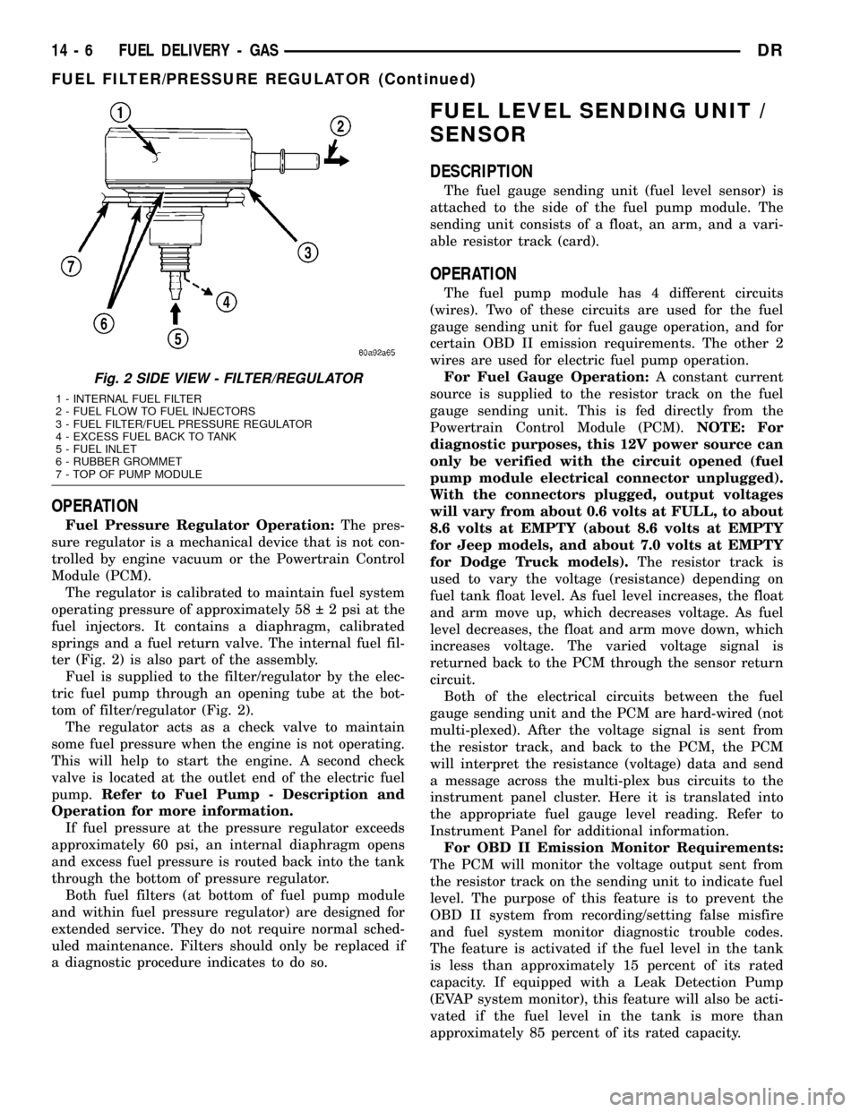
springs and a fuel return valve. The internal fuel fil-
ter (Fig. 2) is also part of the assembly.
Fuel is supplied to the filter/regulator by the elec-
tric fuel pump through an opening tube at the bot-
tom of filter/regulator (Fig. 2).
The regulator acts as a check valve to maintain
some fuel pressure when the engine is not operating.
This will help to start the engine. A second check
valve is located at the outlet end of the electric fuel
pump.Refer to Fuel Pump - Description and
Operation for more information.
If fuel pressure at the pressure regulator exceeds
approximately 60 psi, an internal diaphragm opens
and excess fuel pressure is routed back into the tank
through the bottom of pressure regulator.
Both fuel filters (at bottom of fuel pump module
and within fuel pressure regulator) are designed for
extended service. They do not require normal sched-
uled maintenance. Filters should only be replaced if
a diagnostic procedure indicates to do so.
FUEL LEVEL SENDING UNIT /
SENSOR
DESCRIPTION
The fuel gauge sending unit (fuel level sensor) is
attached to the side of the fuel pump module. The
sending unit consists of a float, an arm, and a vari-
able resistor track (card).
OPERATION
The fuel pump module has 4 different circuits
(wires). Two of these circuits are used for the fuel
gauge sending unit for fuel gauge operation, and for
certain OBD II emission requirements. The other 2
wires are used for electric fuel pump operation.
For Fuel Gauge Operation:A constant current
source is supplied to the resistor track on the fuel
gauge sending unit. This is fed directly from the
Powertrain Control Module (PCM).NOTE: For
diagnostic purposes, this 12V power source can
only be verified with the circuit opened (fuel
pump module electrical connector unplugged).
With the connectors plugged, output voltages
will vary from about 0.6 volts at FULL, to about
8.6 volts at EMPTY (about 8.6 volts at EMPTY
for Jeep models, and about 7.0 volts at EMPTY
for Dodge Truck models).The resistor track is
used to vary the voltage (resistance) depending on
fuel tank float level. As fuel level increases, the float
and arm move up, which decreases voltage. As fuel
level decreases, the float and arm move down, which
increases voltage. The varied voltage signal is
returned back to the PCM through the sensor return
circuit.
Both of the electrical circuits between the fuel
gauge sending unit and the PCM are hard-wired (not
multi-plexed). After the voltage signal is sent from
the resistor track, and back to the PCM, the PCM
will interpret the resistance (voltage) data and send
a message across the multi-plex bus circuits to the
instrument panel cluster. Here it is translated into
the appropriate fuel gauge level reading. Refer to
Instrument Panel for additional information.
For OBD II Emission Monitor Requirements:
The PCM will monitor the voltage output sent from
the resistor track on the sending unit to indicate fuel
level. The purpose of this feature is to prevent the
OBD II system from recording/setting false misfire
and fuel system monitor diagnostic trouble codes.
The feature is activated if the fuel level in the tank
is less than approximately 15 percent of its rated
capacity. If equipped with a Leak Detection Pump
(EVAP system monitor), this feature will also be acti-
vated if the fuel level in the tank is more than
approximately 85 percent of its rated capacity.
Fig. 2 SIDE VIEW - FILTER/REGULATOR
1 - INTERNAL FUEL FILTER
2 - FUEL FLOW TO FUEL INJECTORS
3 - FUEL FILTER/FUEL PRESSURE REGULATOR
4 - EXCESS FUEL BACK TO TANK
5 - FUEL INLET
6 - RUBBER GROMMET
7 - TOP OF PUMP MODULE
14 - 6 FUEL DELIVERY - GASDR
FUEL FILTER/PRESSURE REGULATOR (Continued)
Page 1626 of 2627
FUEL LEVEL SENDING UNIT /
SENSOR
DESCRIPTION
The fuel gauge sending unit (fuel level sensor) is
attached to the side of the fuel tank module. The
sending unit consists of a float, an arm, and a vari-
able resistor track (card).
OPERATION
The fuel tank module on diesel powered models
has 2 different circuits (wires). Two of these circuits
are used at the fuel gauge sending unit for fuel
gauge operation. The diesel engine does not have a
fuel tank module mounted electric fuel pump. The
electric fuel pump (fuel transfer pump) is mounted to
the engine.
For Fuel Gauge Operation:A constant input
voltage source of about 12 volts (battery voltage) is
supplied to the resistor track on the fuel gauge send-
ing unit. This is fed directly from the Engine Control
Module (ECM).NOTE: For diagnostic purposes,
this 12V power source can only be verified with
the circuit opened (fuel tank module electrical
connector unplugged). With the connectors
plugged, output voltages will vary from about .6
volts at FULL, to about 7.0 volts at EMPTY.The
resistor track is used to vary the voltage (resistance)
depending on fuel tank float level. As fuel level
increases, the float and arm move up, which
decreases voltage. As fuel level decreases, the float
and arm move down, which increases voltage. The
varied voltage signal is returned back to the ECM
through the sensor return circuit.
Both of the electrical circuits between the fuel
gauge sending unit and the ECM are hard-wired (not
multi-plexed). After the voltage signal is sent from
the resistor track, and back to the ECM, the ECM
will interpret the resistance (voltage) data and send
a message across the multi-plex bus circuits to the
instrument panel cluster. Here it is translated into
the appropriate fuel gauge level reading. Refer to
Instrument Panel for additional information.
REMOVAL
REMOVAL/INSTALLATION
For diesel removal and installation procedures,
refer to the gas section of Fuel System/Fuel Delivery.
See Fuel Level Sending Unit/Sensor Removal/Instal-
lation.
FUEL LINES
DESCRIPTION
Low-Pressure Lines Are:
²the fuel supply line from fuel tank to fuel trans-
fer (lift) pump.
²the fuel return line back to fuel tank.
²the fuel drain (manifold) line at rear of cylinder
head.
²the fuel supply line from fuel filter to fuel injec-
tion pump.
²the fuel injection pump return line.
High-Pressure Lines Are:
²the fuel line from fuel injection pump to fuel
rail.
²the 6 fuel lines from fuel rail up to injector con-
nector tubes
WARNING: HIGH-PRESSURE FUEL LINES DELIVER
DIESEL FUEL UNDER EXTREME PRESSURE FROM
THE INJECTION PUMP TO THE FUEL INJECTORS.
THIS MAY BE AS HIGH AS 160,000 KPA (23,206
PSI). USE EXTREME CAUTION WHEN INSPECTING
FOR HIGH-PRESSURE FUEL LEAKS. INSPECT FOR
HIGH-PRESSURE FUEL LEAKS WITH A SHEET OF
CARDBOARD. HIGH FUEL INJECTION PRESSURE
CAN CAUSE PERSONAL INJURY IF CONTACT IS
MADE WITH THE SKIN.
OPERATION
High-Pressure Lines
CAUTION: The high-pressure fuel lines must be
held securely in place in their holders. The lines
cannot contact each other or other components. Do
not attempt to weld high-pressure fuel lines or to
repair lines that are damaged. If lines are ever
kinked or bent, they must be replaced. Use only the
recommended lines when replacement of high-pres-
sure fuel line is necessary.
High-pressure fuel lines deliver fuel (under pres-
sure) of up to approximately 160,000 kPa (23,206
PSI) from the injection pump to the fuel injectors.
The lines expand and contract from the high-pres-
sure fuel pulses generated during the injection pro-
cess. All high-pressure fuel lines are of the same
length and inside diameter. Correct high-pressure
fuel line usage and installation is critical to smooth
engine operation.
DRFUEL DELIVERY - DIESEL 14 - 57