1998 DODGE RAM 1500 ABS
[x] Cancel search: ABSPage 1330 of 2627
AIR CLEANER ELEMENT
REMOVAL
Filter Element Only
Housing removal is not necessary for element (fil-
ter) replacement.
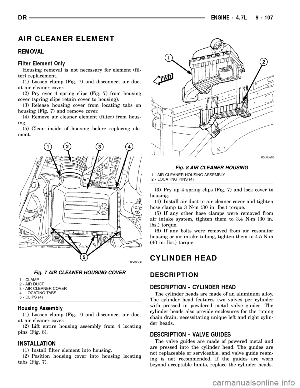
(1) Loosen clamp (Fig. 7) and disconnect air duct
at air cleaner cover.
(2) Pry over 4 spring clips (Fig. 7) from housing
cover (spring clips retain cover to housing).
(3) Release housing cover from locating tabs on
housing (Fig. 7) and remove cover.
(4) Remove air cleaner element (filter) from hous-
ing.
(5) Clean inside of housing before replacing ele-
ment.
Housing Assembly
(1) Loosen clamp (Fig. 7) and disconnect air duct
at air cleaner cover.
(2) Lift entire housing assembly from 4 locating
pins (Fig. 8).
INSTALLATION
(1) Install filter element into housing.
(2) Position housing cover into housing locating
tabs (Fig. 7).(3) Pry up 4 spring clips (Fig. 7) and lock cover to
housing.
(4) Install air duct to air cleaner cover and tighten
hose clamp to 3 N´m (30 in. lbs.) torque.
(5) If any other hose clamps were removed from
air intake system, tighten them to 3.4 N´m (30 in.
lbs.) torque.
(6) If any bolts were removed from air resonator
housing or air intake tubing, tighten them to 4.5 N´m
(40 in. lbs.) torque.
CYLINDER HEAD
DESCRIPTION
DESCRIPTION - CYLINDER HEAD
The cylinder heads are made of an aluminum alloy.
The cylinder head features two valves per cylinder
with pressed in powdered metal valve guides. The
cylinder heads also provide enclosures for the timing
chain drain, necessitating unique left and right cylin-
der heads.
DESCRIPTION - VALVE GUIDES
The valve guides are made of powered metal and
are pressed into the cylinder head. The guides are
not replaceable or serviceable, and valve guide ream-
ing is not recommended. If the guides are worn
beyond acceptable limits, replace the cylinder heads.
Fig. 7 AIR CLEANER HOUSING COVER
1 - CLAMP
2 - AIR DUCT
3 - AIR CLEANER COVER
4 - LOCATING TABS
5 - CLIPS (4)
Fig. 8 AIR CLEANER HOUSING
1 - AIR CLEANER HOUSING ASSEMBLY
2 - LOCATING PINS (4)
DRENGINE - 4.7L 9 - 107
Page 1352 of 2627
the measurement near the middle of the bore, then
repeat the measurement near the bottom of the bore.
(4) Determine taper by subtracting the smaller
diameter from the larger diameter.
(5) Rotate measuring device 90É and repeat steps
above.
(6) Determine out-of-roundness by comparing the
difference between each measurement.
(7) If cylinder bore taper does not exceed 0.025
mm (0.001 inch) and out-of-roundness does not
exceed 0.025 mm (0.001 inch), the cylinder bore can
be honed. If the cylinder bore taper or out- of-round
condition exceeds these maximum limits, the cylinder
block must be replaced. A slight amount of taper
always exists in the cylinder bore after the engine
has been in use for a period of time.
CONNECTING ROD BEARINGS
STANDARD PROCEDURE - CONNECTING ROD
BEARING FITTING
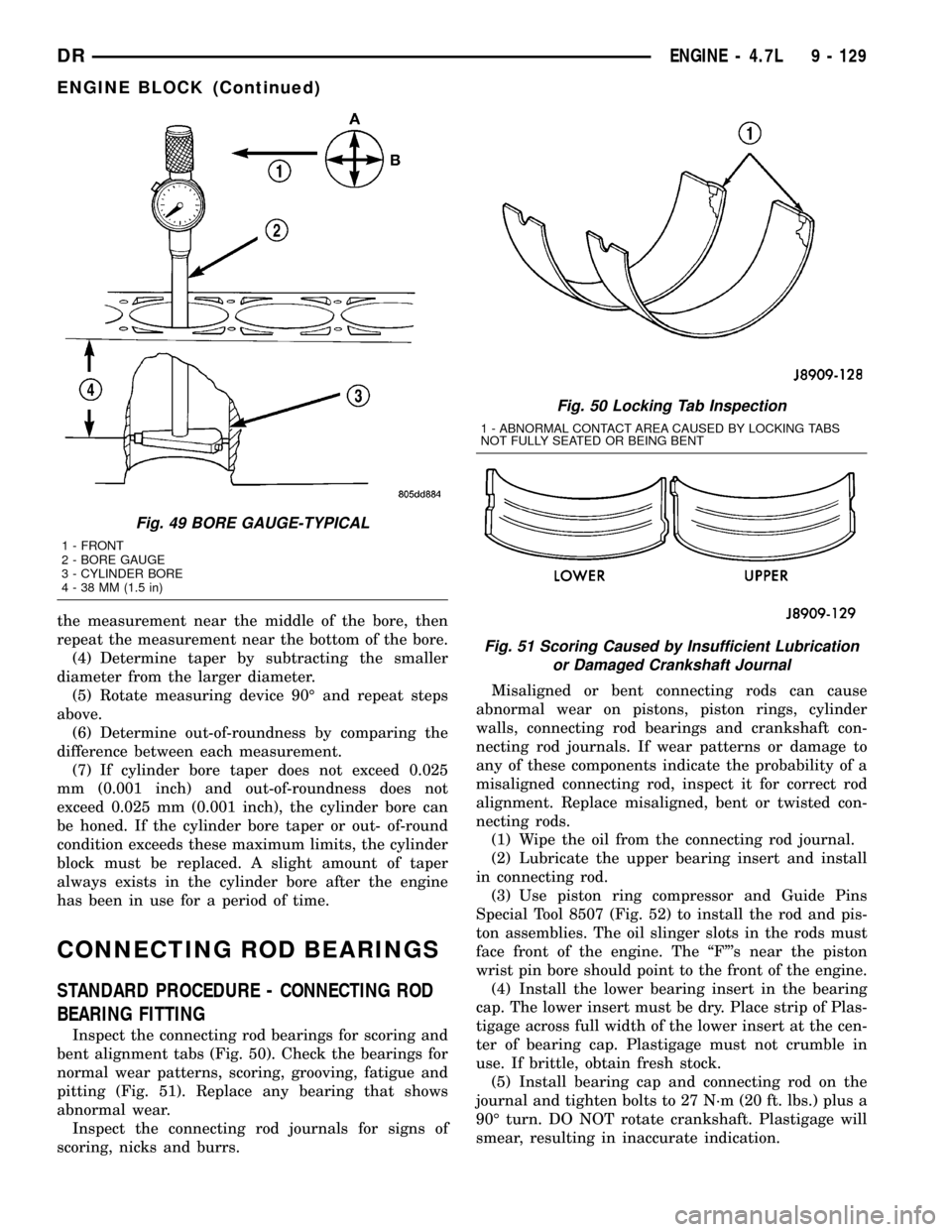
Inspect the connecting rod bearings for scoring and
bent alignment tabs (Fig. 50). Check the bearings for
normal wear patterns, scoring, grooving, fatigue and
pitting (Fig. 51). Replace any bearing that shows
abnormal wear.
Inspect the connecting rod journals for signs of
scoring, nicks and burrs.Misaligned or bent connecting rods can cause
abnormal wear on pistons, piston rings, cylinder
walls, connecting rod bearings and crankshaft con-
necting rod journals. If wear patterns or damage to
any of these components indicate the probability of a
misaligned connecting rod, inspect it for correct rod
alignment. Replace misaligned, bent or twisted con-
necting rods.
(1) Wipe the oil from the connecting rod journal.
(2) Lubricate the upper bearing insert and install
in connecting rod.
(3) Use piston ring compressor and Guide Pins
Special Tool 8507 (Fig. 52) to install the rod and pis-
ton assemblies. The oil slinger slots in the rods must
face front of the engine. The ªFº's near the piston
wrist pin bore should point to the front of the engine.
(4) Install the lower bearing insert in the bearing
cap. The lower insert must be dry. Place strip of Plas-
tigage across full width of the lower insert at the cen-
ter of bearing cap. Plastigage must not crumble in
use. If brittle, obtain fresh stock.
(5) Install bearing cap and connecting rod on the
journal and tighten bolts to 27 N´m (20 ft. lbs.) plus a
90É turn. DO NOT rotate crankshaft. Plastigage will
smear, resulting in inaccurate indication.
Fig. 49 BORE GAUGE-TYPICAL
1 - FRONT
2 - BORE GAUGE
3 - CYLINDER BORE
4 - 38 MM (1.5 in)
Fig. 50 Locking Tab Inspection
1 - ABNORMAL CONTACT AREA CAUSED BY LOCKING TABS
NOT FULLY SEATED OR BEING BENT
Fig. 51 Scoring Caused by Insufficient Lubrication
or Damaged Crankshaft Journal
DRENGINE - 4.7L 9 - 129
ENGINE BLOCK (Continued)
Page 1358 of 2627
nal number 1, 2, 3, 4 and 5. The crankshaft position
sensor target wheel is mounted to the number 8
counter weight on the crankshaft.
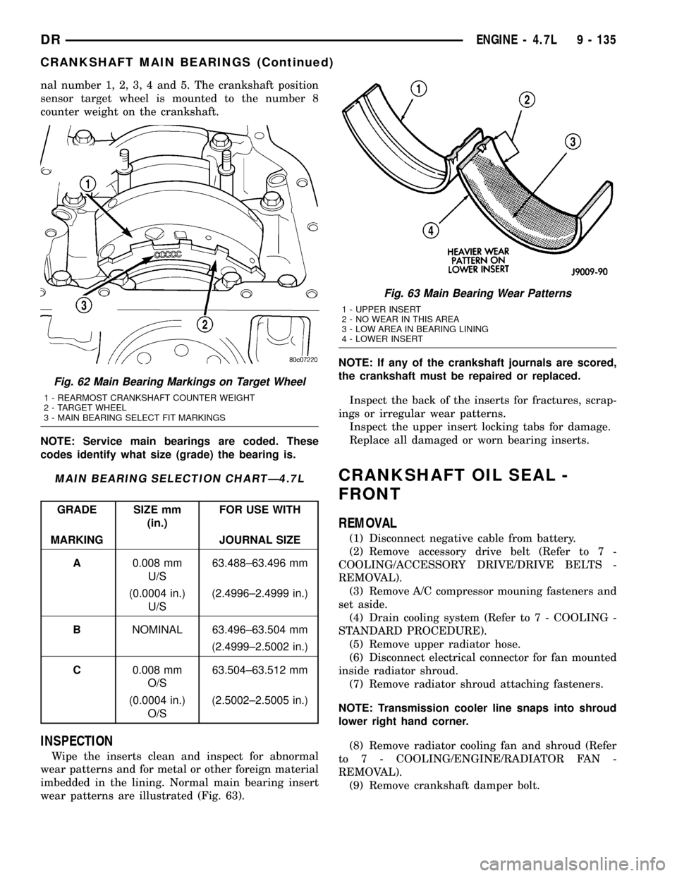
NOTE: Service main bearings are coded. These
codes identify what size (grade) the bearing is.
MAIN BEARING SELECTION CHARTÐ4.7L
GRADE SIZE mm
(in.)FOR USE WITH
MARKING JOURNAL SIZE
A0.008 mm
U/S63.488±63.496 mm
(0.0004 in.)
U/S(2.4996±2.4999 in.)
BNOMINAL 63.496±63.504 mm
(2.4999±2.5002 in.)
C0.008 mm
O/S63.504±63.512 mm
(0.0004 in.)
O/S(2.5002±2.5005 in.)
INSPECTION
Wipe the inserts clean and inspect for abnormal
wear patterns and for metal or other foreign material
imbedded in the lining. Normal main bearing insert
wear patterns are illustrated (Fig. 63).NOTE: If any of the crankshaft journals are scored,
the crankshaft must be repaired or replaced.
Inspect the back of the inserts for fractures, scrap-
ings or irregular wear patterns.
Inspect the upper insert locking tabs for damage.
Replace all damaged or worn bearing inserts.
CRANKSHAFT OIL SEAL -
FRONT
REMOVAL
(1) Disconnect negative cable from battery.
(2) Remove accessory drive belt (Refer to 7 -
COOLING/ACCESSORY DRIVE/DRIVE BELTS -
REMOVAL).
(3) Remove A/C compressor mouning fasteners and
set aside.
(4) Drain cooling system (Refer to 7 - COOLING -
STANDARD PROCEDURE).
(5) Remove upper radiator hose.
(6) Disconnect electrical connector for fan mounted
inside radiator shroud.
(7) Remove radiator shroud attaching fasteners.
NOTE: Transmission cooler line snaps into shroud
lower right hand corner.
(8) Remove radiator cooling fan and shroud (Refer
to 7 - COOLING/ENGINE/RADIATOR FAN -
REMOVAL).
(9) Remove crankshaft damper bolt.
Fig. 62 Main Bearing Markings on Target Wheel
1 - REARMOST CRANKSHAFT COUNTER WEIGHT
2 - TARGET WHEEL
3 - MAIN BEARING SELECT FIT MARKINGS
Fig. 63 Main Bearing Wear Patterns
1 - UPPER INSERT
2 - NO WEAR IN THIS AREA
3 - LOW AREA IN BEARING LINING
4 - LOWER INSERT
DRENGINE - 4.7L 9 - 135
CRANKSHAFT MAIN BEARINGS (Continued)
Page 1379 of 2627
OIL PRESSURE SENSOR/
SWITCH
DESCRIPTION
DESCRIPTION
The 3 wire, solid-state engine oil pressure sensor
(sending unit) is located in an engine oil pressure
gallery.
DESCRIPTION
The 3±wire, electrical/mechanical engine oil pres-
sure sensor (sending unit) is located in an engine oil
pressure gallery.
OPERATION
OPERATION
The oil pressure sensor uses three circuits. They
are:
²A 5 volt power supply from the Powertrain Con-
trol Module (PCM)
²A sensor ground through the PCM's sensor
return
²A signal to the PCM relating to engine oil pres-
sure
The oil pressure sensor has a 3 wire electrical
function very much like the Manifold Absolute Pres-
sure (MAP) sensor. Meaning different pressures
relate to different output voltages.
A 5 volt supply is sent to the sensor from the PCM
to power up the sensor. The sensor returns a voltage
signal back to the PCM relating to engine oil pres-
sure. This signal is then transferred (bussed) to the
instrument panel on either a CCD or PCI bus circuit
(depending on vehicle line) to operate the oil pressure
gauge and the check gauges lamp. Ground for the
sensor is provided by the PCM through a low-noise
sensor return.
OPERATION
The oil pressure sensor uses two circuits. They are:
²A signal to the PCM relating to engine oil pres-
sure
²A sensor ground through the PCM's sensor
return
The oil pressure sensor returns a voltage signal
back to the PCM relating to engine oil pressure. This
signal is then transferred (bussed) to the instrument
panel on a CCD bus circuit to operate the oil pres-
sure gauge and the check gauges lamp. Ground for
the sensor is provided by the PCM through a low-
noise sensor return.
REMOVAL
(1) Disconnect the negative cable from the battery.
(2) Raise vehicle on hoist.
(3) Remove front splash shield.
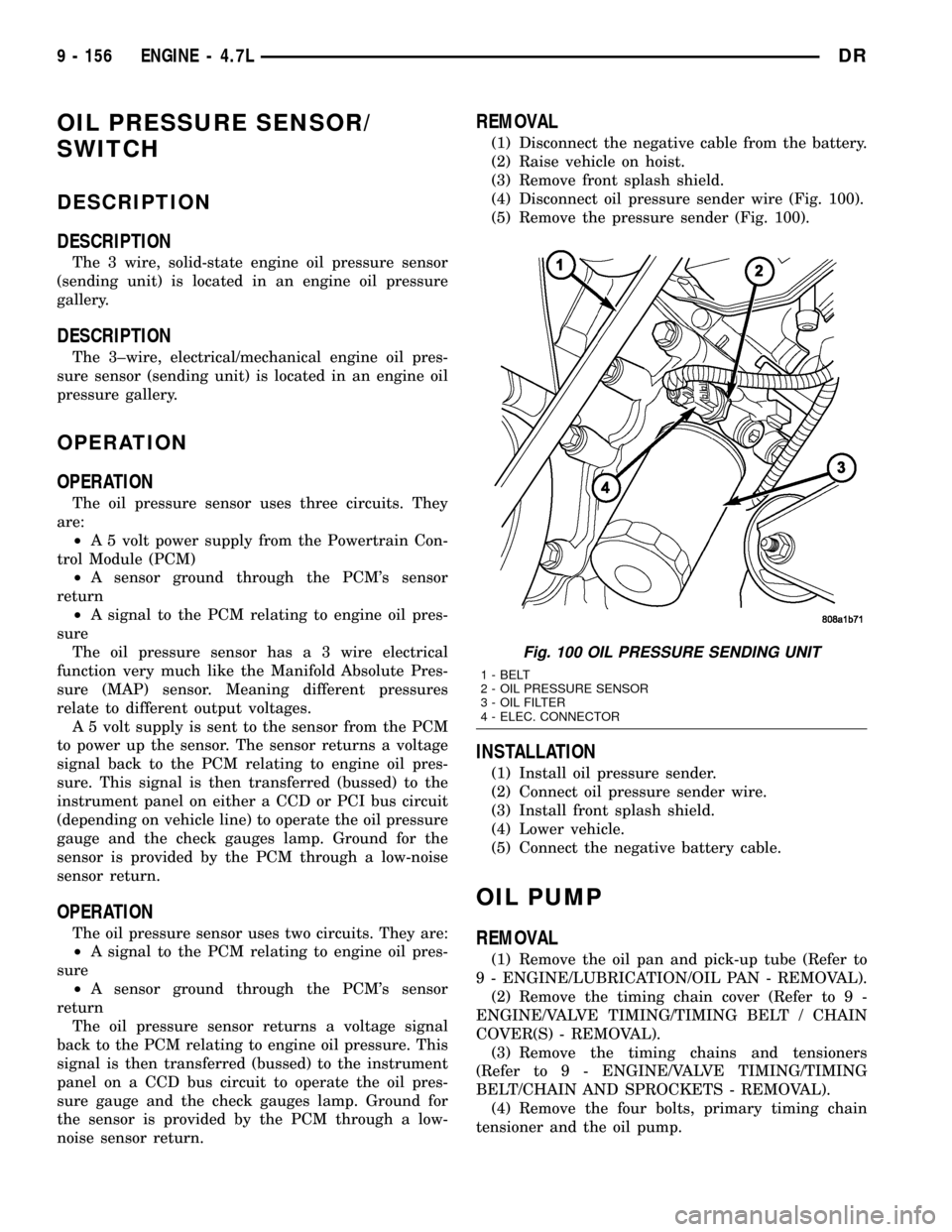
(4) Disconnect oil pressure sender wire (Fig. 100).
(5) Remove the pressure sender (Fig. 100).
INSTALLATION
(1) Install oil pressure sender.
(2) Connect oil pressure sender wire.
(3) Install front splash shield.
(4) Lower vehicle.
(5) Connect the negative battery cable.
OIL PUMP
REMOVAL
(1) Remove the oil pan and pick-up tube (Refer to
9 - ENGINE/LUBRICATION/OIL PAN - REMOVAL).
(2) Remove the timing chain cover (Refer to 9 -
ENGINE/VALVE TIMING/TIMING BELT / CHAIN
COVER(S) - REMOVAL).
(3) Remove the timing chains and tensioners
(Refer to 9 - ENGINE/VALVE TIMING/TIMING
BELT/CHAIN AND SPROCKETS - REMOVAL).
(4) Remove the four bolts, primary timing chain
tensioner and the oil pump.
Fig. 100 OIL PRESSURE SENDING UNIT
1 - BELT
2 - OIL PRESSURE SENSOR
3 - OIL FILTER
4 - ELEC. CONNECTOR
9 - 156 ENGINE - 4.7LDR
Page 1382 of 2627

INSTALLATION
(1) Position the oil pump onto the crankshaft and
install one oil pump retaining bolts.
(2) Position the primary timing chain tensioner
and install three retaining bolts.
(3) Tighten the oil pump and primary timing chain
tensioner retaining bolts to 28 N´m (250 in. lbs.) in
the sequence shown (Fig. 107).
(4) Install the secondary timing chain tensioners
and timing chains (Refer to 9 - ENGINE/VALVE
TIMING/TIMING BELT/CHAIN AND SPROCKETS -
INSTALLATION).
(5) Install the timing chain cover (Refer to 9 -
ENGINE/VALVE TIMING/TIMING BELT / CHAIN
COVER(S) - INSTALLATION).
(6) Install the pick-up tube and oil pan (Refer to 9
- ENGINE/LUBRICATION/OIL PAN - INSTALLA-
TION).
INTAKE MANIFOLD
DESCRIPTION
The intake manifold is made of a composite mate-
rial and features long runners which maximizes low
end torque. The intake manifold uses single plane
sealing which consist of eight individual press in
place port gaskets to prevent leaks. Eight studs and
two bolts are used to fasten the intake to the head.
DIAGNOSIS AND TESTINGÐINTAKE
MANIFOLD LEAKAGE
An intake manifold air leak is characterized by
lower than normal manifold vacuum. Also, one or
more cylinders may not be functioning.
WARNING: USE EXTREME CAUTION WHEN THE
ENGINE IS OPERATING. DO NOT STAND IN A
DIRECT LINE WITH THE FAN. DO NOT PUT YOUR
HANDS NEAR THE PULLEYS, BELTS OR THE FAN.
DO NOT WEAR LOOSE CLOTHING.
(1) Start the engine.
(2) Spray a small stream of water at the suspected
leak area.
(3) If a change in RPM is observed the area of the
suspected leak has been found.
(4) Repair as required.
REMOVAL
(1) Disconnect negative cable from battery.
(2) Remove resonator assembly and air inlet hose.
(3) Disconnect throttle and speed control cables.
(4) Disconnect electrical connectors for the follow-
ing components:
²Manifold Absolute Pressure (MAP) Sensor
²Intake Air Temperature (IAT) Sensor
²Throttle Position (TPS) Sensor
²Coolant Temperature (CTS) Sensor
²Idle Air Control (IAC) Motor
(5) Disconnect brake booster hose and positive
crankcase ventilation (PCV) hose.
(6) Disconnect generator electrical connections.
(7) Disconnect air conditioning compressor electri-
cal connections.
(8) Disconnect left and right radio suppressor
straps.
(9) Disconnect and remove ignition coil towers
(Refer to 8 - ELECTRICAL/IGNITION CONTROL/
IGNITION COIL - REMOVAL).
(10) Remove top oil dipstick tube retaining bolt
and ground strap.
(11) Bleed fuel system (Refer to 14 - FUEL SYS-
TEM/FUEL DELIVERY - STANDARD PROCE-
DURE).
(12) Remove fuel rail (Refer to 14 - FUEL SYS-
TEM/FUEL DELIVERY/FUEL RAIL - REMOVAL).
(13) Remove throttle body assembly and mounting
bracket.
(14) Drain cooling system below coolant tempera-
ture level (Refer to 7 - COOLING - STANDARD
PROCEDURE).
(15) Remove the heater hoses from the engine
front cover and the heater core.
Fig. 107 Oil Pump And Primary Timing Chain
Tensioner Tightening Sequence
DRENGINE - 4.7L 9 - 159
OIL PUMP (Continued)
Page 1383 of 2627
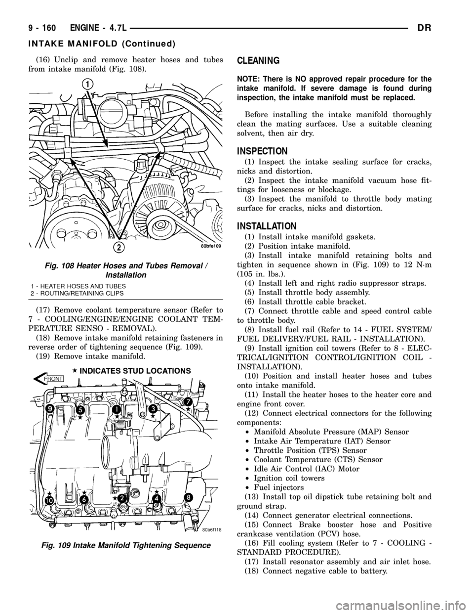
(16) Unclip and remove heater hoses and tubes
from intake manifold (Fig. 108).
(17) Remove coolant temperature sensor (Refer to
7 - COOLING/ENGINE/ENGINE COOLANT TEM-
PERATURE SENSO - REMOVAL).
(18) Remove intake manifold retaining fasteners in
reverse order of tightening sequence (Fig. 109).
(19) Remove intake manifold.CLEANING
NOTE: There is NO approved repair procedure for the
intake manifold. If severe damage is found during
inspection, the intake manifold must be replaced.
Before installing the intake manifold thoroughly
clean the mating surfaces. Use a suitable cleaning
solvent, then air dry.
INSPECTION
(1) Inspect the intake sealing surface for cracks,
nicks and distortion.
(2) Inspect the intake manifold vacuum hose fit-
tings for looseness or blockage.
(3) Inspect the manifold to throttle body mating
surface for cracks, nicks and distortion.
INSTALLATION
(1) Install intake manifold gaskets.
(2) Position intake manifold.
(3) Install intake manifold retaining bolts and
tighten in sequence shown in (Fig. 109) to 12 N´m
(105 in. lbs.).
(4) Install left and right radio suppressor straps.
(5) Install throttle body assembly.
(6) Install throttle cable bracket.
(7) Connect throttle cable and speed control cable
to throttle body.
(8) Install fuel rail (Refer to 14 - FUEL SYSTEM/
FUEL DELIVERY/FUEL RAIL - INSTALLATION).
(9) Install ignition coil towers (Refer to 8 - ELEC-
TRICAL/IGNITION CONTROL/IGNITION COIL -
INSTALLATION).
(10) Position and install heater hoses and tubes
onto intake manifold.
(11) Install the heater hoses to the heater core and
engine front cover.
(12) Connect electrical connectors for the following
components:
²Manifold Absolute Pressure (MAP) Sensor
²Intake Air Temperature (IAT) Sensor
²Throttle Position (TPS) Sensor
²Coolant Temperature (CTS) Sensor
²Idle Air Control (IAC) Motor
²Ignition coil towers
²Fuel injectors
(13) Install top oil dipstick tube retaining bolt and
ground strap.
(14) Connect generator electrical connections.
(15) Connect Brake booster hose and Positive
crankcase ventilation (PCV) hose.
(16) Fill cooling system (Refer to 7 - COOLING -
STANDARD PROCEDURE).
(17) Install resonator assembly and air inlet hose.
(18) Connect negative cable to battery.
Fig. 108 Heater Hoses and Tubes Removal /
Installation
1 - HEATER HOSES AND TUBES
2 - ROUTING/RETAINING CLIPS
Fig. 109 Intake Manifold Tightening Sequence
9 - 160 ENGINE - 4.7LDR
INTAKE MANIFOLD (Continued)
Page 1422 of 2627
AIR INTAKE SYSTEM
REMOVAL
Filter Element Only
Housing removal is not necessary for element (fil-
ter) replacement.
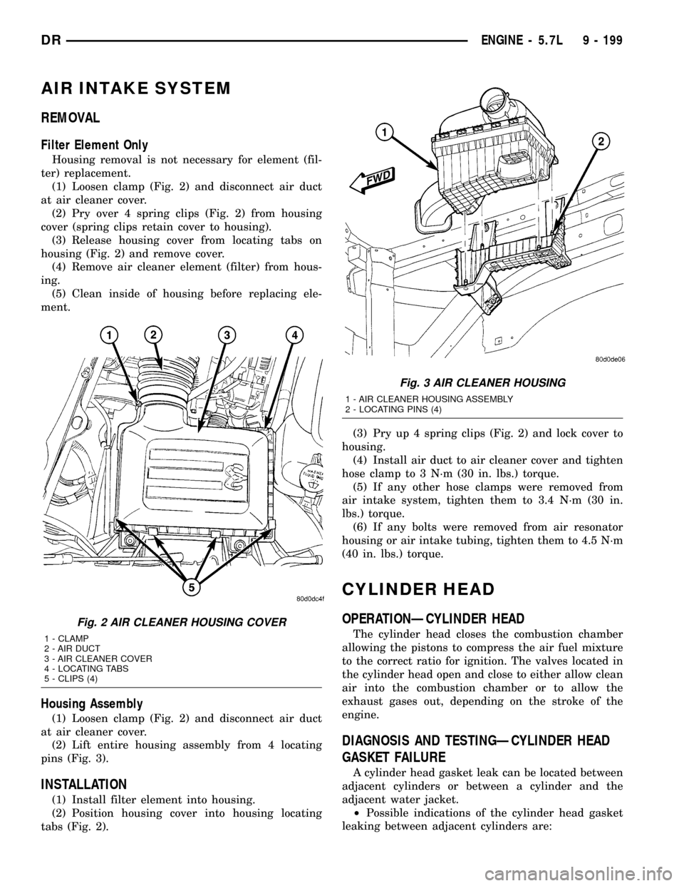
(1) Loosen clamp (Fig. 2) and disconnect air duct
at air cleaner cover.
(2) Pry over 4 spring clips (Fig. 2) from housing
cover (spring clips retain cover to housing).
(3) Release housing cover from locating tabs on
housing (Fig. 2) and remove cover.
(4) Remove air cleaner element (filter) from hous-
ing.
(5) Clean inside of housing before replacing ele-
ment.
Housing Assembly
(1) Loosen clamp (Fig. 2) and disconnect air duct
at air cleaner cover.
(2) Lift entire housing assembly from 4 locating
pins (Fig. 3).
INSTALLATION
(1) Install filter element into housing.
(2) Position housing cover into housing locating
tabs (Fig. 2).(3) Pry up 4 spring clips (Fig. 2) and lock cover to
housing.
(4) Install air duct to air cleaner cover and tighten
hose clamp to 3 N´m (30 in. lbs.) torque.
(5) If any other hose clamps were removed from
air intake system, tighten them to 3.4 N´m (30 in.
lbs.) torque.
(6) If any bolts were removed from air resonator
housing or air intake tubing, tighten them to 4.5 N´m
(40 in. lbs.) torque.
CYLINDER HEAD
OPERATIONÐCYLINDER HEAD
The cylinder head closes the combustion chamber
allowing the pistons to compress the air fuel mixture
to the correct ratio for ignition. The valves located in
the cylinder head open and close to either allow clean
air into the combustion chamber or to allow the
exhaust gases out, depending on the stroke of the
engine.
DIAGNOSIS AND TESTINGÐCYLINDER HEAD
GASKET FAILURE
A cylinder head gasket leak can be located between
adjacent cylinders or between a cylinder and the
adjacent water jacket.
²Possible indications of the cylinder head gasket
leaking between adjacent cylinders are:
Fig. 2 AIR CLEANER HOUSING COVER
1 - CLAMP
2 - AIR DUCT
3 - AIR CLEANER COVER
4 - LOCATING TABS
5 - CLIPS (4)
Fig. 3 AIR CLEANER HOUSING
1 - AIR CLEANER HOUSING ASSEMBLY
2 - LOCATING PINS (4)
DRENGINE - 5.7L 9 - 199
Page 1431 of 2627
shaft counterweight has grade identification marks
stamped into it. These marks are read from left to
right, corresponding with journal number 1, 2, 3, 4
and 5.
NOTE: Service main bearings are coded. These
codes identify what size (grade) the bearing is.
MAIN BEARING SELECTION CHART - 5.7L
GRADE SIZE mm
(in.)FOR USE WITH
MARKING JOURNAL SIZE
A0.008 mm
U/S64.988±64.995 mm
(0.0004 in.)
U/S(2.5585± 2.5588in.)
BNOMINAL 64.996±65.004 mm
(2.5588±2.5592 in.)
C0.008 mm
O/S65.005±65.012 mm
(0.0004 in.)
O/S(2.5592±2.5595 in.)
INSPECTION
Wipe the inserts clean and inspect for abnormal
wear patterns and for metal or other foreign material
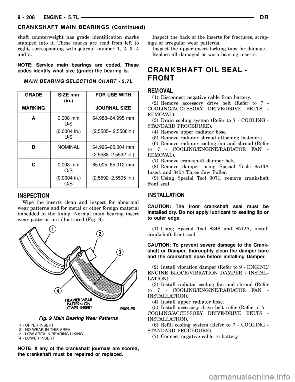
imbedded in the lining. Normal main bearing insert
wear patterns are illustrated (Fig. 9).
NOTE: If any of the crankshaft journals are scored,
the crankshaft must be repaired or replaced.Inspect the back of the inserts for fractures, scrap-
ings or irregular wear patterns.
Inspect the upper insert locking tabs for damage.
Replace all damaged or worn bearing inserts.
CRANKSHAFT OIL SEAL -
FRONT
REMOVAL
(1) Disconnect negative cable from battery.
(2) Remove accessory drive belt (Refer to 7 -
COOLING/ACCESSORY DRIVE/DRIVE BELTS -
REMOVAL).
(3) Drain cooling system (Refer to 7 - COOLING -
STANDARD PROCEDURE).
(4) Remove upper radiator hose.
(5) Remove radiator shroud attaching fasteners.
(6) Remove radiator cooling fan and shroud (Refer
to 7 - COOLING/ENGINE/RADIATOR FAN -
REMOVAL).
(7) Remove crankshaft damper bolt.
(8) Remove damper using Special Tools 8513A
Insert and 8454 Three Jaw Puller.
(9) Using Special Tool 9071, remove crankshaft
front seal.
INSTALLATION
CAUTION: The front crankshaft seal must be
installed dry. Do not apply lubricant to sealing lip or
to outer edge.
(1) Using Special Tool 8348 and 8512A, install
crankshaft front seal.
CAUTION: To prevent severe damage to the Crank-
shaft or Damper, thoroughly clean the damper bore
and the crankshaft nose before installing Damper.
(2) Install vibration damper (Refer to 9 - ENGINE/
ENGINE BLOCK/VIBRATION DAMPER - INSTAL-
LATION).
(3) Install radiator cooling fan and shroud (Refer
to 7 - COOLING/ENGINE/RADIATOR FAN -
INSTALLATION).
(4) Install upper radiator hose.
(5) Install accessory drive belt refer (Refer to 7 -
COOLING/ACCESSORY DRIVE/DRIVE BELTS -
INSTALLATION).
(6) Refill cooling system (Refer to 7 - COOLING -
STANDARD PROCEDURE).
(7) Connect negative cable to battery.
Fig. 9 Main Bearing Wear Patterns
1 - UPPER INSERT
2 - NO WEAR IN THIS AREA
3 - LOW AREA IN BEARING LINING
4 - LOWER INSERT
9 - 208 ENGINE - 5.7LDR
CRANKSHAFT MAIN BEARINGS (Continued)