1998 DODGE RAM 1500 heater
[x] Cancel search: heaterPage 1622 of 2627
(3) Check condition of relay terminals and PDC
connector terminals for damage or corrosion. Repair
if necessary before installing relay.
(4) Check for pin height (pin height should be the
same for all terminals within the PDC connector).
Repair if necessary before installing relay.
INSTALLATION
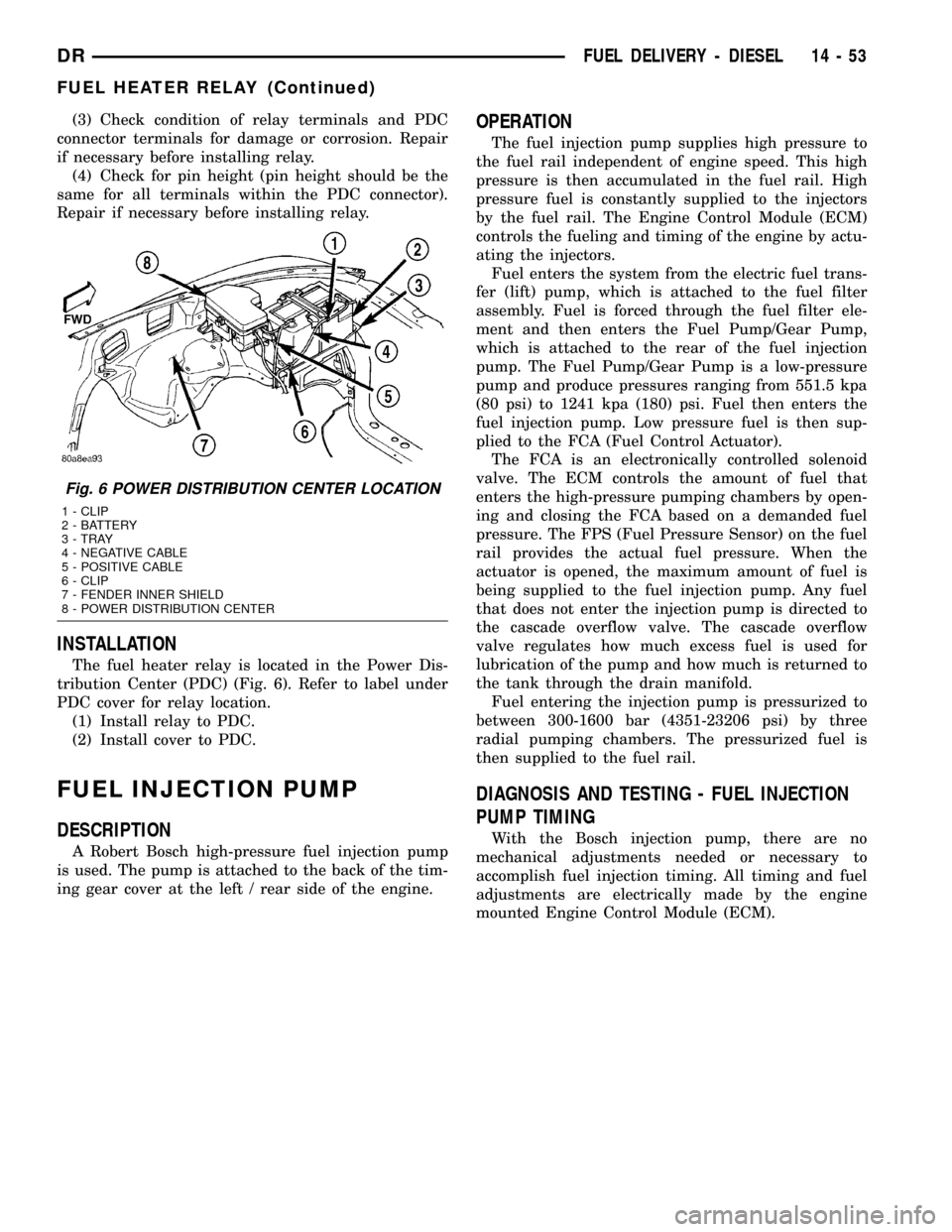
The fuel heater relay is located in the Power Dis-
tribution Center (PDC) (Fig. 6). Refer to label under
PDC cover for relay location.
(1) Install relay to PDC.
(2) Install cover to PDC.
FUEL INJECTION PUMP
DESCRIPTION
A Robert Bosch high-pressure fuel injection pump
is used. The pump is attached to the back of the tim-
ing gear cover at the left / rear side of the engine.
OPERATION
The fuel injection pump supplies high pressure to
the fuel rail independent of engine speed. This high
pressure is then accumulated in the fuel rail. High
pressure fuel is constantly supplied to the injectors
by the fuel rail. The Engine Control Module (ECM)
controls the fueling and timing of the engine by actu-
ating the injectors.
Fuel enters the system from the electric fuel trans-
fer (lift) pump, which is attached to the fuel filter
assembly. Fuel is forced through the fuel filter ele-
ment and then enters the Fuel Pump/Gear Pump,
which is attached to the rear of the fuel injection
pump. The Fuel Pump/Gear Pump is a low-pressure
pump and produce pressures ranging from 551.5 kpa
(80 psi) to 1241 kpa (180) psi. Fuel then enters the
fuel injection pump. Low pressure fuel is then sup-
plied to the FCA (Fuel Control Actuator).
The FCA is an electronically controlled solenoid
valve. The ECM controls the amount of fuel that
enters the high-pressure pumping chambers by open-
ing and closing the FCA based on a demanded fuel
pressure. The FPS (Fuel Pressure Sensor) on the fuel
rail provides the actual fuel pressure. When the
actuator is opened, the maximum amount of fuel is
being supplied to the fuel injection pump. Any fuel
that does not enter the injection pump is directed to
the cascade overflow valve. The cascade overflow
valve regulates how much excess fuel is used for
lubrication of the pump and how much is returned to
the tank through the drain manifold.
Fuel entering the injection pump is pressurized to
between 300-1600 bar (4351-23206 psi) by three
radial pumping chambers. The pressurized fuel is
then supplied to the fuel rail.
DIAGNOSIS AND TESTING - FUEL INJECTION
PUMP TIMING
With the Bosch injection pump, there are no
mechanical adjustments needed or necessary to
accomplish fuel injection timing. All timing and fuel
adjustments are electrically made by the engine
mounted Engine Control Module (ECM).
Fig. 6 POWER DISTRIBUTION CENTER LOCATION
1 - CLIP
2 - BATTERY
3 - TRAY
4 - NEGATIVE CABLE
5 - POSITIVE CABLE
6 - CLIP
7 - FENDER INNER SHIELD
8 - POWER DISTRIBUTION CENTER
DRFUEL DELIVERY - DIESEL 14 - 53
FUEL HEATER RELAY (Continued)
Page 1623 of 2627

REMOVAL
CAUTION: Cleanliness cannot be overemphasized
when handling or replacing diesel fuel system com-
ponents. This especially includes the fuel injectors,
high-pressure fuel lines and fuel injection pump.
Very tight tolerances are used with these parts. Dirt
contamination could cause rapid part wear and pos-
sible plugging of fuel injector nozzle tip holes. This
in turn could lead to possible engine misfire.
Always wash/clean any fuel system component
thoroughly before disassembly and then air dry.
Cap or cover any open part after disassembly.
Before assembly, examine each part for dirt, grease
or other contaminants and clean if necessary. When
installing new parts, lubricate them with clean
engine oil or clean diesel fuel only.
(1) Disconnect both negative battery cables at both
batteries. Cover and isolate ends of both cables.
(2) Remove intake manifold air intake tube (above
injection pump) and its rubber connector hose (Fig.
7).
(3) Remove accessory drive belt.
(4) Thoroughly clean the rear of injection pump,
and attachment points for its 3 fuel lines (Fig. 8).
Also clean the opposite ends of these same 3 lines at
their attachment points.
(5) Disconnect Fuel Control Actuator (FCA) electri-
cal connector at rear of injection pump (Fig. 9).
CAUTION: Whenever a fuel line fitting is connected
to a secondary fitting, always use a back-up wrench
on the secondary fitting. Do not allow the second-
ary fitting to rotate.
(6) Remove fuel line (injection pump-to-fuel pres-
sure limiting valve).
(7) Remove fuel line (injection pump-to-fuel rail).
Use back-up wrench on fitting at fuel pump.
(8) Remove fuel line (injection pump-to-fuel filter
housing).
(9) Remove fuel pump drive gear access cover
(plate) with a 3/8º drive ratchet. Plate is threaded to
timing gear cover (Fig. 10).
(10) Remove fuel pump drive gear mounting nut
and washer.
(11) Attach C3428B, or L4407A (or equivalent)
gear puller (Fig. 11) to pump drive gear with 2 bolts,
and separate gear from pump (a keyway is not used
on this particular injection pump). Leave drive gear
hanging loose within timing gear cover.
(12) Remove 3 injection pump mounting nuts (Fig.
12), and remove pump from engine.
Fig. 7 INTAKE TUBE AND CONNECTING HOSE
1 - MANIFOLD ABOVE HEATERS
2 - RUBBER CONNECTING HOSE
3 - METAL INTAKE TUBE
4 - CLAMPS (2)
Fig. 8 OVERFLOW VALVE
1 - BANJO BOLTS
2 - PUMP MOUNTING NUTS (3)
3 - FUEL INJECTION PUMP
4 - CASCADE OVERFLOW VALVE
14 - 54 FUEL DELIVERY - DIESELDR
FUEL INJECTION PUMP (Continued)
Page 1627 of 2627
WARNING: USE EXTREME CAUTION WHEN
INSPECTING FOR HIGH-PRESSURE FUEL LEAKS.
INSPECT FOR HIGH-PRESSURE FUEL LEAKS WITH
A SHEET OF CARDBOARD. HIGH FUEL INJECTION
PRESSURE CAN CAUSE PERSONAL INJURY IF
CONTACT IS MADE WITH THE SKIN.
DIAGNOSIS AND TESTING - HIGH-PRESSURE
FUEL LINE LEAKS
High-pressure fuel line leaks can cause starting
problems and poor engine performance.
WARNING: DUE TO EXTREME FUEL PRESSURES
OF UP TO 160,000 kPa (23,206 PSI), USE EXTREME
CAUTION WHEN INSPECTING FOR HIGH-PRES-
SURE FUEL LEAKS. DO NOT GET YOUR HAND OR
A FINGER NEAR A SUSPECTED LEAK. INSPECT
FOR HIGH-PRESSURE FUEL LEAKS WITH A SHEET
OF CARDBOARD. HIGH FUEL INJECTION PRES-
SURE CAN CAUSE PERSONAL INJURY IF CON-
TACT IS MADE WITH THE SKIN.
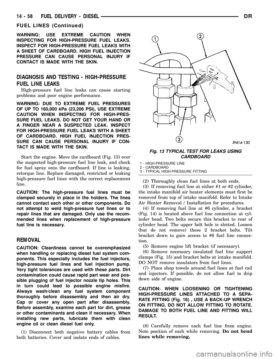
Start the engine. Move the cardboard (Fig. 13) over
the suspected high-pressure fuel line leak, and check
for fuel spray onto the cardboard. If line is leaking,
retorque line. Replace damaged, restricted or leaking
high-pressure fuel lines with the correct replacement
line.
CAUTION: The high-pressure fuel lines must be
clamped securely in place in the holders. The lines
cannot contact each other or other components. Do
not attempt to weld high-pressure fuel lines or to
repair lines that are damaged. Only use the recom-
mended lines when replacement of high-pressure
fuel line is necessary.
REMOVAL
CAUTION: Cleanliness cannot be overemphasized
when handling or replacing diesel fuel system com-
ponents. This especially includes the fuel injectors,
high-pressure fuel lines and fuel injection pump.
Very tight tolerances are used with these parts. Dirt
contamination could cause rapid part wear and pos-
sible plugging of fuel injector nozzle tip holes. This
in turn could lead to possible engine misfire.
Always wash/clean any fuel system component
thoroughly before disassembly and then air dry.
Cap or cover any open part after disassembly.
Before assembly, examine each part for dirt, grease
or other contaminants and clean if necessary. When
installing new parts, lubricate them with clean
engine oil or clean diesel fuel only.
(1) Disconnect both negative battery cables from
both batteries. Cover and isolate ends of cables.(2) Thoroughly clean fuel lines at both ends.
(3) If removing fuel line at either #1 or #2 cylinder,
the intake manifold air heater elements must first be
removed from top of intake manifold. Refer to Intake
Air Heater Removal / Installation for procedures.
(4) If removing fuel line at #6 cylinder, a bracket
(Fig. 14) is located above fuel line connection at cyl-
inder head. Two bolts secure this bracket to rear of
cylinder head. The upper bolt hole is slotted. Loosen
(but do not remove) these 2 bracket bolts. Tilt
bracket down to gain access to #6 fuel line connec-
tion.
(5) Remove engine lift bracket (if necessary).
(6) Remove necessary insulated fuel line support
clamps (Fig. 15) and bracket bolts at intake manifold.
DO NOT remove insulators from fuel lines.
(7) Place shop towels around fuel lines at fuel rail
and injectors. If possible, do not allow fuel to drip
down side of engine.
CAUTION: WHEN LOOSENING OR TIGHTENING
HIGH-PRESSURE LINES ATTACHED TO A SEPA-
RATE FITTING (Fig. 16) , USE A BACK-UP WRENCH
ON FITTING. DO NOT ALLOW FITTING TO ROTATE.
DAMAGE TO BOTH FUEL LINE AND FITTING WILL
RESULT.
(8) Carefully remove each fuel line from engine.
Note position of each while removing.Do not bend
lines while removing.
Fig. 13 TYPICAL TEST FOR LEAKS USING
CARDBOARD
1 - HIGH-PRESSURE LINE
2 - CARDBOARD
3 - TYPICAL HIGH-PRESSURE FITTING
14 - 58 FUEL DELIVERY - DIESELDR
FUEL LINES (Continued)
Page 1629 of 2627
INSTALLATION
All high-pressure fuel lines are of the same length
and inside diameter. Correct high-pressure fuel line
usage and installation is critical to smooth engine
operation.
CAUTION: Anytime a high-pressure line is removed
from the engine, its fuel connector nut at the cylin-
der head must first be retorqued. Refer to Torque
Specifications.
(1) Tighten fuel lines at high pressure injector con-
nector. Refer to Torque Specifications.
(2) Position fuel line support clamp(s) to fuel
line(s). Install clamp nuts/bolts and tighten finger
tight.
(3) Position proper fuel line to proper injector on
engine. Tighten fittings hand tight at both ends of
line.
(4) Tighten fuel lines at fuel rail. Refer to Torque
Specifications.
(5) Tighten clamp/support nuts and bolts. Refer to
Torque Specifications.
(6) Install engine lifting bracket and bolt. Refer to
Torque Specifications.
(7) If fuel line at either #1 or #2 cylinder has been
replaced, install intake manifold air heater elements
to top of intake manifold. Refer to Intake Air Heater
Removal / Installation for procedures.
(8) If fuel line at #6 cylinder has been replaced, tilt
metal bracket upward and tighten 2 bolts at rear of
cylinder head. Refer to Torque Specifications.
(9) Install remaining fuel line support clamps and
bracket bolts at intake manifold. Refer to Torque
Specifications.
(10) Connect both negative battery cables to both
batteries.
(11) Prime fuel system. Refer to Fuel System
Priming.
(12) Check lines/fittings for leaks.
FUEL PRESSURE SENSOR
DESCRIPTION
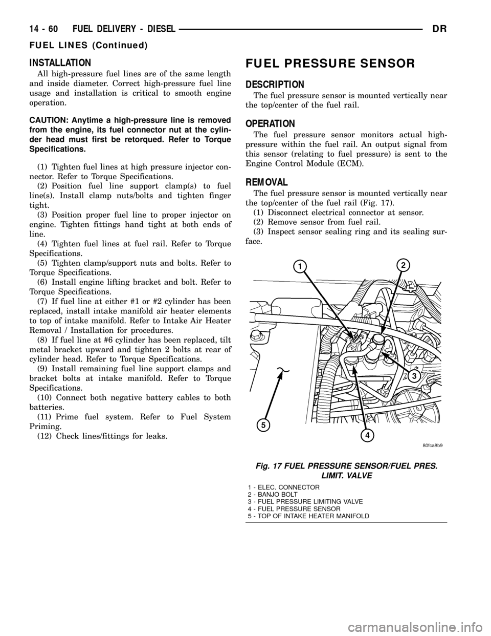
The fuel pressure sensor is mounted vertically near
the top/center of the fuel rail.
OPERATION
The fuel pressure sensor monitors actual high-
pressure within the fuel rail. An output signal from
this sensor (relating to fuel pressure) is sent to the
Engine Control Module (ECM).
REMOVAL
The fuel pressure sensor is mounted vertically near
the top/center of the fuel rail (Fig. 17).
(1) Disconnect electrical connector at sensor.
(2) Remove sensor from fuel rail.
(3) Inspect sensor sealing ring and its sealing sur-
face.
Fig. 17 FUEL PRESSURE SENSOR/FUEL PRES.
LIMIT. VALVE
1 - ELEC. CONNECTOR
2 - BANJO BOLT
3 - FUEL PRESSURE LIMITING VALVE
4 - FUEL PRESSURE SENSOR
5 - TOP OF INTAKE HEATER MANIFOLD
14 - 60 FUEL DELIVERY - DIESELDR
FUEL LINES (Continued)
Page 1630 of 2627
INSTALLATION
(1) Inspect fuel pressure sensor sealing surface.
(2) Lubricate sensor threads with clean diesel fuel.
(3) Install sensor into fuel rail.
(4) To prevent leaks, sensormustbe tightened to
prescribed torque. Refer to Torque Specifications.
(5) Connect electrical connector to sensor.
(6) Start engine and check for fuel leaks.
FUEL PRESSURE LIMITING
VA LV E
DESCRIPTION
The fuel pressure limiting valve is located on the
top of the fuel rail.
OPERATION
Fuel pressure at the fuel rail is monitored by the
fuel rail pressure sensor. If fuel pressure becomes
excessive, the pressure limiting valve opens and
vents excess pressure into the fuel drain circuit.
REMOVAL
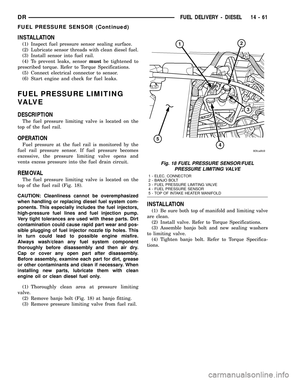
The fuel pressure limiting valve is located on the
top of the fuel rail (Fig. 18).
CAUTION: Cleanliness cannot be overemphasized
when handling or replacing diesel fuel system com-
ponents. This especially includes the fuel injectors,
high-pressure fuel lines and fuel injection pump.
Very tight tolerances are used with these parts. Dirt
contamination could cause rapid part wear and pos-
sible plugging of fuel injector nozzle tip holes. This
in turn could lead to possible engine misfire.
Always wash/clean any fuel system component
thoroughly before disassembly and then air dry.
Cap or cover any open part after disassembly.
Before assembly, examine each part for dirt, grease
or other contaminants and clean if necessary. When
installing new parts, lubricate them with clean
engine oil or clean diesel fuel only.
(1) Thoroughly clean area at pressure limiting
valve.
(2) Remove banjo bolt (Fig. 18) at banjo fitting.
(3) Remove pressure limiting valve from fuel rail.
INSTALLATION
(1) Be sure both top of manifold and limiting valve
are clean.
(2) Install valve. Refer to Torque Specifications.
(3) Assemble banjo bolt and new sealing washers
to limiting valve.
(4) Tighten banjo bolt. Refer to Torque Specifica-
tions.
Fig. 18 FUEL PRESSURE SENSOR/FUEL
PRESSURE LIMITING VALVE
1 - ELEC. CONNECTOR
2 - BANJO BOLT
3 - FUEL PRESSURE LIMITING VALVE
4 - FUEL PRESSURE SENSOR
5 - TOP OF INTAKE HEATER MANIFOLD
DRFUEL DELIVERY - DIESEL 14 - 61
FUEL PRESSURE SENSOR (Continued)
Page 1635 of 2627
CASCADE OVERFLOW VALVE
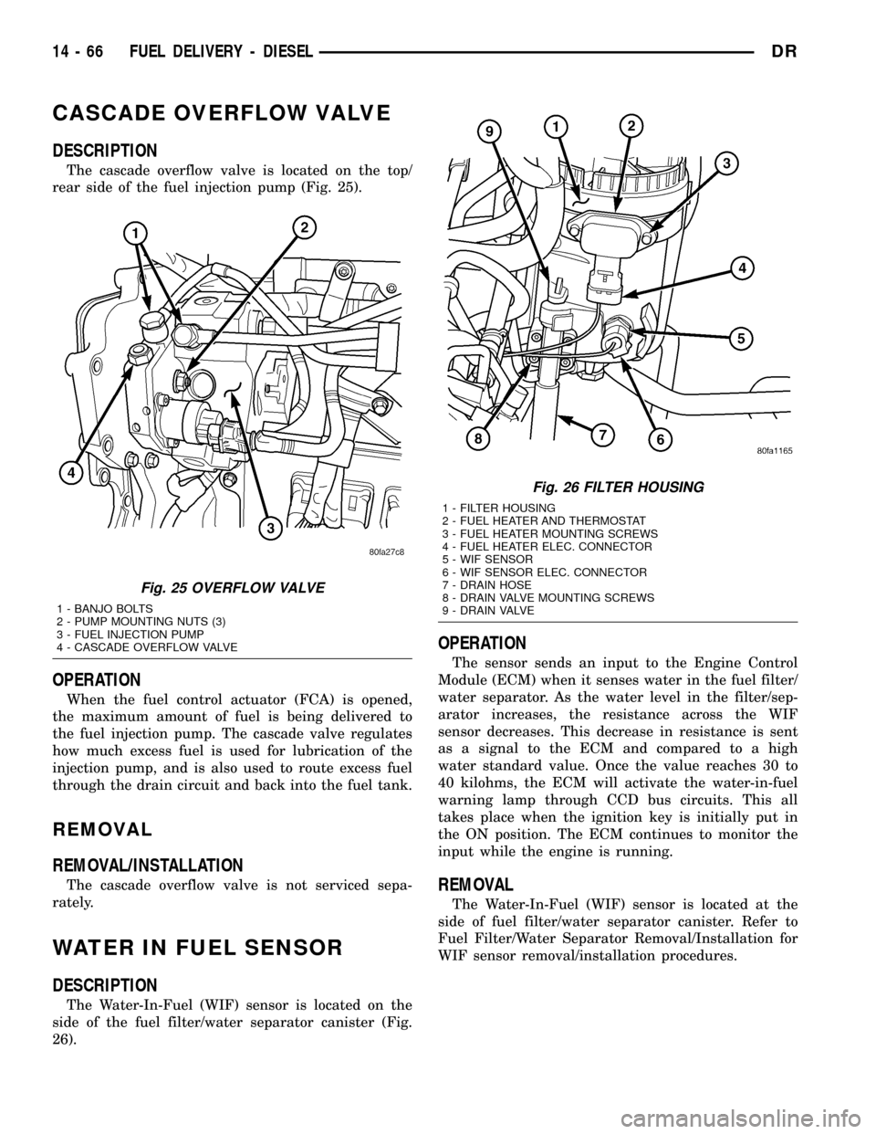
DESCRIPTION
The cascade overflow valve is located on the top/
rear side of the fuel injection pump (Fig. 25).
OPERATION
When the fuel control actuator (FCA) is opened,
the maximum amount of fuel is being delivered to
the fuel injection pump. The cascade valve regulates
how much excess fuel is used for lubrication of the
injection pump, and is also used to route excess fuel
through the drain circuit and back into the fuel tank.
REMOVAL
REMOVAL/INSTALLATION
The cascade overflow valve is not serviced sepa-
rately.
WATER IN FUEL SENSOR
DESCRIPTION
The Water-In-Fuel (WIF) sensor is located on the
side of the fuel filter/water separator canister (Fig.
26).
OPERATION
The sensor sends an input to the Engine Control
Module (ECM) when it senses water in the fuel filter/
water separator. As the water level in the filter/sep-
arator increases, the resistance across the WIF
sensor decreases. This decrease in resistance is sent
as a signal to the ECM and compared to a high
water standard value. Once the value reaches 30 to
40 kilohms, the ECM will activate the water-in-fuel
warning lamp through CCD bus circuits. This all
takes place when the ignition key is initially put in
the ON position. The ECM continues to monitor the
input while the engine is running.
REMOVAL
The Water-In-Fuel (WIF) sensor is located at the
side of fuel filter/water separator canister. Refer to
Fuel Filter/Water Separator Removal/Installation for
WIF sensor removal/installation procedures.
Fig. 25 OVERFLOW VALVE
1 - BANJO BOLTS
2 - PUMP MOUNTING NUTS (3)
3 - FUEL INJECTION PUMP
4 - CASCADE OVERFLOW VALVE
Fig. 26 FILTER HOUSING
1 - FILTER HOUSING
2 - FUEL HEATER AND THERMOSTAT
3 - FUEL HEATER MOUNTING SCREWS
4 - FUEL HEATER ELEC. CONNECTOR
5 - WIF SENSOR
6 - WIF SENSOR ELEC. CONNECTOR
7 - DRAIN HOSE
8 - DRAIN VALVE MOUNTING SCREWS
9 - DRAIN VALVE
14 - 66 FUEL DELIVERY - DIESELDR
Page 1637 of 2627

FUEL INJECTION - DIESEL
TABLE OF CONTENTS
page page
ACCELERATOR PEDAL POSITION SENSOR
DESCRIPTION.........................68
OPERATION...........................68
REMOVAL.............................68
INSTALLATION.........................71
CAMSHAFT POSITION SENSOR
DESCRIPTION.........................71
OPERATION...........................71
REMOVAL.............................72
INSTALLATION.........................72
CRANKSHAFT POSITION SENSOR
DESCRIPTION.........................72
OPERATION...........................72
REMOVAL.............................73
INSTALLATION.........................73
FUEL CONTROL ACTUATOR
DESCRIPTION.........................74
OPERATION...........................74
REMOVAL.............................74
FUEL INJECTOR
DESCRIPTION.........................74
OPERATION...........................74
REMOVAL.............................75
INSTALLATION.........................77
FUEL INJECTOR RAIL
DESCRIPTION.........................78
OPERATION...........................78
REMOVAL.............................78
INSTALLATION.........................78INLET AIR TEMPERATURE SENSOR/
PRESSURE SENSOR
DESCRIPTION.........................79
OPERATION...........................79
REMOVAL.............................79
INSTALLATION.........................79
INTAKE AIR HEATER
DESCRIPTION.........................80
OPERATION...........................80
REMOVAL.............................80
INSTALLATION.........................80
INTAKE AIR HEATER RELAY
DESCRIPTION.........................82
OPERATION...........................82
REMOVAL.............................82
INSTALLATION.........................82
INTAKE AIR TEMPERATURE SENSOR/MAP
SENSOR
DESCRIPTION.........................82
OPERATION...........................82
REMOVAL.............................82
INSTALLATION.........................82
MAP SENSOR
DESCRIPTION.........................83
THROTTLE CONTROL CABLE
REMOVAL.............................83
INSTALLATION.........................84
PTO SWITCH
DESCRIPTION.........................85
OPERATION...........................85
ACCELERATOR PEDAL
POSITION SENSOR
DESCRIPTION
Engine Mounted Sensor:The APPS assembly is
located at the top-left-front of the engine. A plastic
cover is used to cover the assembly. The actual sen-
sor is located behind its mounting bracket.
Battery Tray Mounted Sensor:The Accelerator
Pedal Position Sensor (APPS) assembly is located
under the vehicle battery tray. A cable connects the
assembly to the accelerator pedal. A plastic cover
with a movable door is used to cover the assembly.
OPERATION
Engine Mounted Sensor:The Accelerator Pedal
Position Sensor (APPS) is a linear potentiometer. Itprovides the Engine Control Module (ECM) with a
DC voltage signal proportional to the angle, or posi-
tion of the accelerator pedal.
Battery Tray Mounted Sensor:The APPS pro-
vides the ECM with two DC voltage signals which
change as the position of the accelerator changes.
One of the DC voltage signals will be half the voltage
of the other signal.
REMOVAL
Engine Mounted Sensor :
The APPS is serviced (replaced) as one assembly
including the lever, brackets and sensor. The APPS is
calibrated to its mounting bracket. The APPS assem-
bly is located at left-front of engine below plastic
cable/lever/linkage cover (Fig. 1).
14 - 68 FUEL INJECTION - DIESELDR
Page 1647 of 2627

(6) Install injector into cylinder head with male
connector port facing the intake manifold. Push down
on fuel injector mounting flange to engage o-ring and
seat injector.
(7) Tightening Sequence:
(a) Install fuel injector holdown clamp (mount-
ing flange) bolts.Do a preliminary tightening
of these bolts to 5 N´m (44 in. lbs.) torque.
This preliminary tightening insures the fuel
injector is seated and centered.
(b) After tightening, relieve bolt torque, but
leave both bolts threaded in place.
(c) Install high-pressure connector and retaining
nut. Do a preliminary tightening to 15 N´m (11 ft.
lbs.) torque.
(d) Alternately tighten injector holdown bolts to
10 N´m (89 in. lbs.) torque.
(e) Do a final tightening of the high-pressure
connector and retaining nut. Tighten to 50 N´m (37
ft. lbs.) torque.
(8) Connect injector solenoid wires and nuts to top
of injectors (Fig. 18). Tighten connector nuts to 1.25
N´m (11 in. lbs.) torque.Be very careful not to
overtighten these nuts as damage to fuel injec-
tor will occur.
(9) Install exhaust rocker arm assembly. Refer to
Engine.
(10) Set exhaust valve lash. Refer to Engine.
(11) Install high pressure fuel line. Refer to Torque
Specifications.Be sure to use a secondary
back-up wrench on the connector nut (fitting)
while torquing fuel line fitting.Refer to Fuel Line
Installation for additional information.
(12) Install valve cover. Refer to Engine.
(13) Install breather assembly.
(14) Connect negative battery cables to both bat-
teries.
FUEL INJECTOR RAIL
DESCRIPTION
The fuel injector rail is bolted to the top of the
intake manifold.
OPERATION
The fuel rail is used as a distribution device to
supply high-pressure fuel to the high-pressure fuel
lines.
REMOVAL
CAUTION: Cleanliness cannot be overemphasized
when handling or replacing diesel fuel system com-
ponents. This especially includes the fuel injectors,
high-pressure fuel lines and fuel injection pump.Very tight tolerances are used with these parts. Dirt
contamination could cause rapid part wear and pos-
sible plugging of fuel injector nozzle tip holes. This
in turn could lead to possible engine misfire.
Always wash/clean any fuel system component
thoroughly before disassembly and then air dry.
Cap or cover any open part after disassembly.
Before assembly, examine each part for dirt, grease
or other contaminants and clean if necessary. When
installing new parts, lubricate them with clean
engine oil or clean diesel fuel only.
(1) Disconnect both negative battery cables at both
batteries. Isolate ends of both cables.
(2) Disconnect electrical connector at fuel pressure
sensor.
(3) Remove banjo bolt at fuel limiting valve.
(4) Disconnect necessary wiring harness retention
clips from intake manifold.
(5) Lift 2 rubber covers to gain access to positive
(+), intake heater cable nuts. Remove 2 nuts and
remove 2 cables from studs.
(6) Carefully remove 4 high-pressure fuel lines
from top of injector rail engine. Note position of each
line while removing.Do not bend lines while
removing.
CAUTION: WHEN LOOSENING OR TIGHTENING
HIGH-PRESSURE LINES ATTACHED TO A SEPA-
RATE FITTING, USE A BACK-UP WRENCH ON FIT-
TING. DO NOT ALLOW FITTING TO ROTATE.
DAMAGE TO BOTH FUEL LINE AND FITTING WILL
RESULT.
(7) Carefully remove 2 high-pressure fuel lines at
each end of injector rail. Note position of each line
while removing.Do not bend lines while remov-
ing.
(8) Remove fuel line connecting injector pump to
fuel rail.
(9) Remove 3 injector rail mounting bolts (Fig. 22).
(10) Remove rail from top of intake manifold.
INSTALLATION
(1) Clean any dirt/debris from top of intake mani-
fold and bottom of fuel rail.
(2) Position fuel rail to top of manifold and install
3 mounting bolts. Refer to Torque Specifications.
(3) Install all high-pressure lines to rail. Refer to
Fuel Lines for procedures.
(4) Reposition wiring harness to intake manifold
and install new tie wraps.
(5) Install and tighten fuel limiting valve banjo
bolt. Refer to Torque Specifications.
(6) Connect electrical connector to fuel pressure
sensor.
(7) Position 2 positive (+) cables to intake heater
studs. Install 2 nuts.
14 - 78 FUEL INJECTION - DIESELDR
FUEL INJECTOR (Continued)