1998 DODGE RAM 1500 battery temp
[x] Cancel search: battery tempPage 1155 of 2627
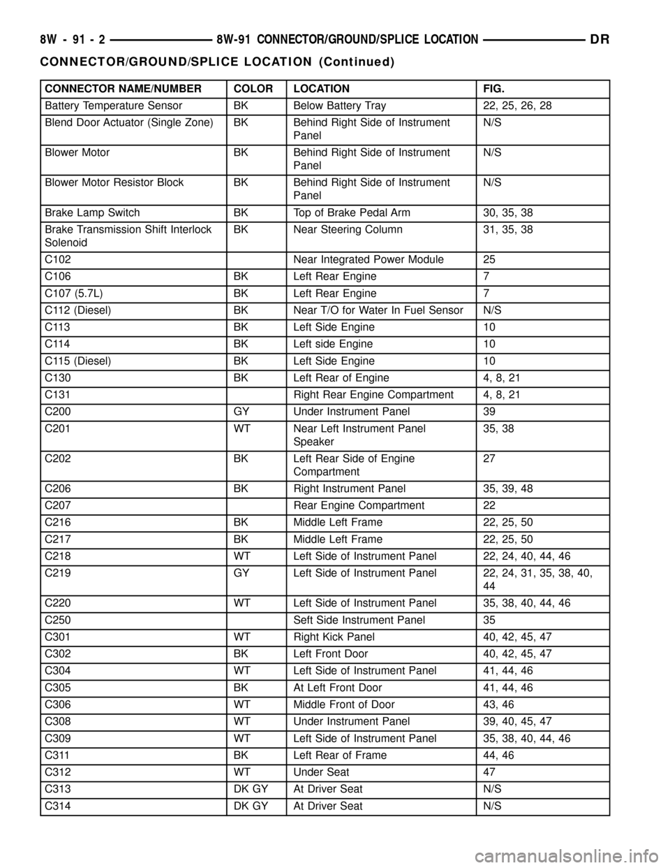
CONNECTOR NAME/NUMBER COLOR LOCATION FIG.
Battery Temperature Sensor BK Below Battery Tray 22, 25, 26, 28
Blend Door Actuator (Single Zone) BK Behind Right Side of Instrument
PanelN/S
Blower Motor BK Behind Right Side of Instrument
PanelN/S
Blower Motor Resistor Block BK Behind Right Side of Instrument
PanelN/S
Brake Lamp Switch BK Top of Brake Pedal Arm 30, 35, 38
Brake Transmission Shift Interlock
SolenoidBK Near Steering Column 31, 35, 38
C102 Near Integrated Power Module 25
C106 BK Left Rear Engine 7
C107 (5.7L) BK Left Rear Engine 7
C112 (Diesel) BK Near T/O for Water In Fuel Sensor N/S
C113 BK Left Side Engine 10
C114 BK Left side Engine 10
C115 (Diesel) BK Left Side Engine 10
C130 BK Left Rear of Engine 4, 8, 21
C131 Right Rear Engine Compartment 4, 8, 21
C200 GY Under Instrument Panel 39
C201 WT Near Left Instrument Panel
Speaker35, 38
C202 BK Left Rear Side of Engine
Compartment27
C206 BK Right Instrument Panel 35, 39, 48
C207 Rear Engine Compartment 22
C216 BK Middle Left Frame 22, 25, 50
C217 BK Middle Left Frame 22, 25, 50
C218 WT Left Side of Instrument Panel 22, 24, 40, 44, 46
C219 GY Left Side of Instrument Panel 22, 24, 31, 35, 38, 40,
44
C220 WT Left Side of Instrument Panel 35, 38, 40, 44, 46
C250 Seft Side Instrument Panel 35
C301 WT Right Kick Panel 40, 42, 45, 47
C302 BK Left Front Door 40, 42, 45, 47
C304 WT Left Side of Instrument Panel 41, 44, 46
C305 BK At Left Front Door 41, 44, 46
C306 WT Middle Front of Door 43, 46
C308 WT Under Instrument Panel 39, 40, 45, 47
C309 WT Left Side of Instrument Panel 35, 38, 40, 44, 46
C311 BK Left Rear of Frame 44, 46
C312 WT Under Seat 47
C313 DK GY At Driver Seat N/S
C314 DK GY At Driver Seat N/S
8W - 91 - 2 8W-91 CONNECTOR/GROUND/SPLICE LOCATIONDR
CONNECTOR/GROUND/SPLICE LOCATION (Continued)
Page 1220 of 2627
(3) Connect the electrical connectors by pushing
straight on and rotating the connector arm inboard,
until the connector is firmly locked in place on the
module assembly.
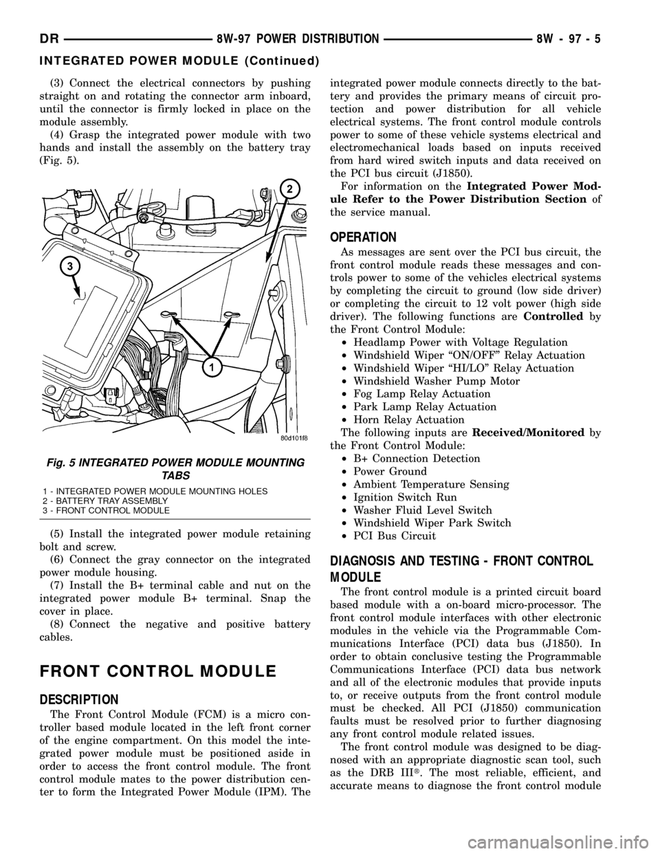
(4) Grasp the integrated power module with two
hands and install the assembly on the battery tray
(Fig. 5).
(5) Install the integrated power module retaining
bolt and screw.
(6) Connect the gray connector on the integrated
power module housing.
(7) Install the B+ terminal cable and nut on the
integrated power module B+ terminal. Snap the
cover in place.
(8) Connect the negative and positive battery
cables.
FRONT CONTROL MODULE
DESCRIPTION
The Front Control Module (FCM) is a micro con-
troller based module located in the left front corner
of the engine compartment. On this model the inte-
grated power module must be positioned aside in
order to access the front control module. The front
control module mates to the power distribution cen-
ter to form the Integrated Power Module (IPM). Theintegrated power module connects directly to the bat-
tery and provides the primary means of circuit pro-
tection and power distribution for all vehicle
electrical systems. The front control module controls
power to some of these vehicle systems electrical and
electromechanical loads based on inputs received
from hard wired switch inputs and data received on
the PCI bus circuit (J1850).
For information on theIntegrated Power Mod-
ule Refer to the Power Distribution Sectionof
the service manual.
OPERATION
As messages are sent over the PCI bus circuit, the
front control module reads these messages and con-
trols power to some of the vehicles electrical systems
by completing the circuit to ground (low side driver)
or completing the circuit to 12 volt power (high side
driver). The following functions areControlledby
the Front Control Module:
²Headlamp Power with Voltage Regulation
²Windshield Wiper ªON/OFFº Relay Actuation
²Windshield Wiper ªHI/LOº Relay Actuation
²Windshield Washer Pump Motor
²Fog Lamp Relay Actuation
²Park Lamp Relay Actuation
²Horn Relay Actuation
The following inputs areReceived/Monitoredby
the Front Control Module:
²B+ Connection Detection
²Power Ground
²Ambient Temperature Sensing
²Ignition Switch Run
²Washer Fluid Level Switch
²Windshield Wiper Park Switch
²PCI Bus Circuit
DIAGNOSIS AND TESTING - FRONT CONTROL
MODULE
The front control module is a printed circuit board
based module with a on-board micro-processor. The
front control module interfaces with other electronic
modules in the vehicle via the Programmable Com-
munications Interface (PCI) data bus (J1850). In
order to obtain conclusive testing the Programmable
Communications Interface (PCI) data bus network
and all of the electronic modules that provide inputs
to, or receive outputs from the front control module
must be checked. All PCI (J1850) communication
faults must be resolved prior to further diagnosing
any front control module related issues.
The front control module was designed to be diag-
nosed with an appropriate diagnostic scan tool, such
as the DRB IIIt. The most reliable, efficient, and
accurate means to diagnose the front control module
Fig. 5 INTEGRATED POWER MODULE MOUNTING
TABS
1 - INTEGRATED POWER MODULE MOUNTING HOLES
2 - BATTERY TRAY ASSEMBLY
3 - FRONT CONTROL MODULE
DR8W-97 POWER DISTRIBUTION 8W - 97 - 5
INTEGRATED POWER MODULE (Continued)
Page 1221 of 2627
requires the use of a DRB IIItscan tool and the
proper Body Diagnostic Procedures manual.
Before any testing of the front control module is
attempted, the battery should be fully charged and
all wire harness and ground connections inspected
around the affected areas on the vehicle.
REMOVAL
(1) Disconnect the positive and negative battery
cables from the battery.
(2) Partially remove the integrated power module
from the engine compartment (Refer to 8 - ELECTRI-
CAL/POWER DISTRIBUTION/INTEGRATED
POWER MODULE - REMOVAL).
(3) Remove the front control module retaining
screws.
(4) Using both hands, pull the front control module
straightfrom the integrated power module assembly
to disconnect the 49-way electrical connector and
remove the front control module from the vehicle.
INSTALLATION
(1) Install the front control module on the inte-
grated power module assembly by pushing the
49-way electrical connector straight in.
(2) Install the front control module retaining
screws. Torque the screws to 7 in. lbs.
(3) Install the integrated power module (Refer to 8
- ELECTRICAL/POWER DISTRIBUTION/INTE-
GRATED POWER MODULE - INSTALLATION).
(4) Connect the positive and negative battery
cables.
IOD FUSE
DESCRIPTION
All vehicles are equipped with an Ignition-Off
Draw (IOD) fuse that is disconnected within the Inte-
grated Power Module when the vehicle is shipped
from the factory. Dealer personnel are to reconnect
the IOD fuse in the Integrated Power Module as part
of the preparation procedures performed just prior to
new vehicle delivery.
A laser printed fuse layout map is integral to the
Integrated Power Module cover to ensure proper fuse
identification. The IOD fuse is a 20 ampere mini
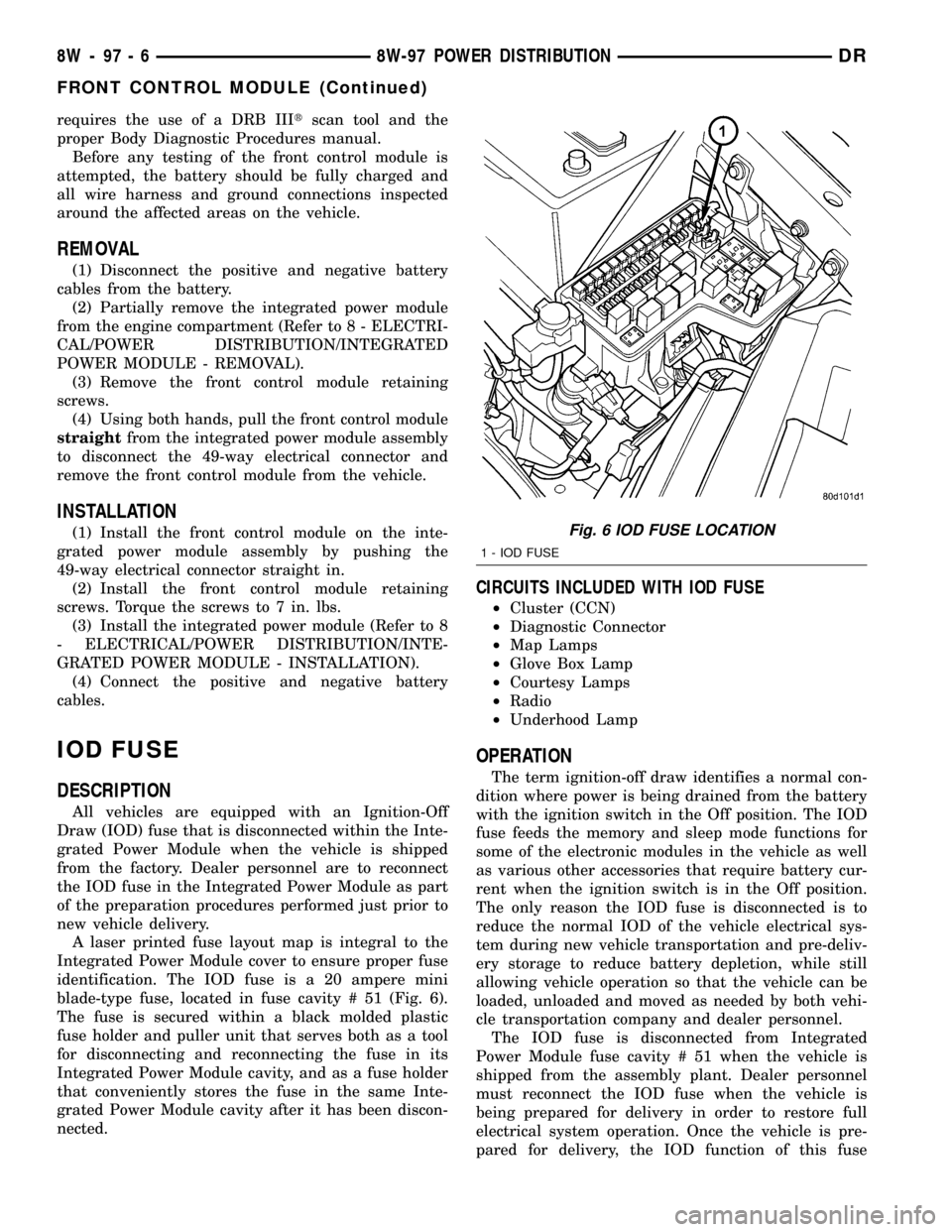
blade-type fuse, located in fuse cavity # 51 (Fig. 6).
The fuse is secured within a black molded plastic
fuse holder and puller unit that serves both as a tool
for disconnecting and reconnecting the fuse in its
Integrated Power Module cavity, and as a fuse holder
that conveniently stores the fuse in the same Inte-
grated Power Module cavity after it has been discon-
nected.
CIRCUITS INCLUDED WITH IOD FUSE
²Cluster (CCN)
²Diagnostic Connector
²Map Lamps
²Glove Box Lamp
²Courtesy Lamps
²Radio
²Underhood Lamp
OPERATION
The term ignition-off draw identifies a normal con-
dition where power is being drained from the battery
with the ignition switch in the Off position. The IOD
fuse feeds the memory and sleep mode functions for
some of the electronic modules in the vehicle as well
as various other accessories that require battery cur-
rent when the ignition switch is in the Off position.
The only reason the IOD fuse is disconnected is to
reduce the normal IOD of the vehicle electrical sys-
tem during new vehicle transportation and pre-deliv-
ery storage to reduce battery depletion, while still
allowing vehicle operation so that the vehicle can be
loaded, unloaded and moved as needed by both vehi-
cle transportation company and dealer personnel.
The IOD fuse is disconnected from Integrated
Power Module fuse cavity # 51 when the vehicle is
shipped from the assembly plant. Dealer personnel
must reconnect the IOD fuse when the vehicle is
being prepared for delivery in order to restore full
electrical system operation. Once the vehicle is pre-
pared for delivery, the IOD function of this fuse
Fig. 6 IOD FUSE LOCATION
1 - IOD FUSE
8W - 97 - 6 8W-97 POWER DISTRIBUTIONDR
FRONT CONTROL MODULE (Continued)
Page 1231 of 2627
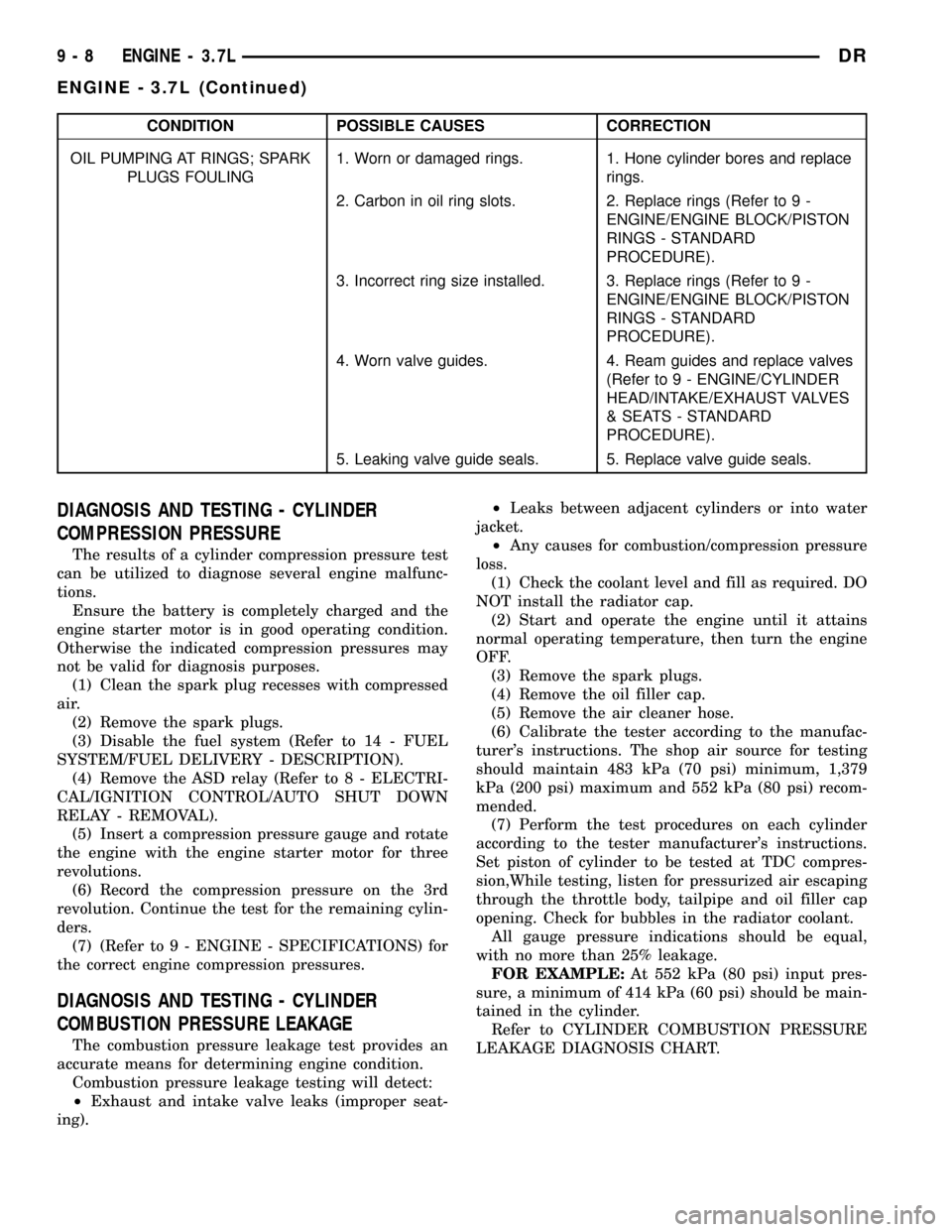
CONDITION POSSIBLE CAUSES CORRECTION
OIL PUMPING AT RINGS; SPARK
PLUGS FOULING1. Worn or damaged rings. 1. Hone cylinder bores and replace
rings.
2. Carbon in oil ring slots. 2. Replace rings (Refer to 9 -
ENGINE/ENGINE BLOCK/PISTON
RINGS - STANDARD
PROCEDURE).
3. Incorrect ring size installed. 3. Replace rings (Refer to 9 -
ENGINE/ENGINE BLOCK/PISTON
RINGS - STANDARD
PROCEDURE).
4. Worn valve guides. 4. Ream guides and replace valves
(Refer to 9 - ENGINE/CYLINDER
HEAD/INTAKE/EXHAUST VALVES
& SEATS - STANDARD
PROCEDURE).
5. Leaking valve guide seals. 5. Replace valve guide seals.
DIAGNOSIS AND TESTING - CYLINDER
COMPRESSION PRESSURE
The results of a cylinder compression pressure test
can be utilized to diagnose several engine malfunc-
tions.
Ensure the battery is completely charged and the
engine starter motor is in good operating condition.
Otherwise the indicated compression pressures may
not be valid for diagnosis purposes.
(1) Clean the spark plug recesses with compressed
air.
(2) Remove the spark plugs.
(3) Disable the fuel system (Refer to 14 - FUEL
SYSTEM/FUEL DELIVERY - DESCRIPTION).
(4) Remove the ASD relay (Refer to 8 - ELECTRI-
CAL/IGNITION CONTROL/AUTO SHUT DOWN
RELAY - REMOVAL).
(5) Insert a compression pressure gauge and rotate
the engine with the engine starter motor for three
revolutions.
(6) Record the compression pressure on the 3rd
revolution. Continue the test for the remaining cylin-
ders.
(7) (Refer to 9 - ENGINE - SPECIFICATIONS) for
the correct engine compression pressures.
DIAGNOSIS AND TESTING - CYLINDER
COMBUSTION PRESSURE LEAKAGE
The combustion pressure leakage test provides an
accurate means for determining engine condition.
Combustion pressure leakage testing will detect:
²Exhaust and intake valve leaks (improper seat-
ing).²Leaks between adjacent cylinders or into water
jacket.
²Any causes for combustion/compression pressure
loss.
(1) Check the coolant level and fill as required. DO
NOT install the radiator cap.
(2) Start and operate the engine until it attains
normal operating temperature, then turn the engine
OFF.
(3) Remove the spark plugs.
(4) Remove the oil filler cap.
(5) Remove the air cleaner hose.
(6) Calibrate the tester according to the manufac-
turer's instructions. The shop air source for testing
should maintain 483 kPa (70 psi) minimum, 1,379
kPa (200 psi) maximum and 552 kPa (80 psi) recom-
mended.
(7) Perform the test procedures on each cylinder
according to the tester manufacturer's instructions.
Set piston of cylinder to be tested at TDC compres-
sion,While testing, listen for pressurized air escaping
through the throttle body, tailpipe and oil filler cap
opening. Check for bubbles in the radiator coolant.
All gauge pressure indications should be equal,
with no more than 25% leakage.
FOR EXAMPLE:At 552 kPa (80 psi) input pres-
sure, a minimum of 414 kPa (60 psi) should be main-
tained in the cylinder.
Refer to CYLINDER COMBUSTION PRESSURE
LEAKAGE DIAGNOSIS CHART.
9 - 8 ENGINE - 3.7LDR
ENGINE - 3.7L (Continued)
Page 1233 of 2627
of oil and coolant. Can be used on threaded and
machined parts under all temperatures. This mate-
rial is used on engines with multi-layer steel (MLS)
cylinder head gaskets. This material also will pre-
vent corrosion. MopartGasket Sealant is available in
a 13 oz. aerosol can or 4oz./16 oz. can w/applicator.
FORM-IN-PLACE GASKET AND SEALER
APPLICATION
Assembling parts using a form-in-place gasket
requires care but it's easier than using precut gas-
kets.
MopartGasket Maker material should be applied
sparingly 1 mm (0.040 in.) diameter or less of sealant
to one gasket surface. Be certain the material sur-
rounds each mounting hole. Excess material can eas-
ily be wiped off. Components should be torqued in
place within 15 minutes. The use of a locating dowel
is recommended during assembly to prevent smear-
ing material off the location.
MopartEngine RTV GEN II or ATF RTV gasket
material should be applied in a continuous bead
approximately 3 mm (0.120 in.) in diameter. All
mounting holes must be circled. For corner sealing, a
3.17 or 6.35 mm (1/8 or 1/4 in.) drop is placed in the
center of the gasket contact area. Uncured sealant
may be removed with a shop towel. Components
should be torqued in place while the sealant is still
wet to the touch (within 10 minutes). The usage of a
locating dowel is recommended during assembly to
prevent smearing material off the location.
MopartGasket Sealant in an aerosol can should be
applied using a thin, even coat sprayed completely
over both surfaces to be joined, and both sides of a
gasket. Then proceed with assembly. Material in a
can w/applicator can be brushed on evenly over the
sealing surfaces. Material in an aerosol can should be
used on engines with multi-layer steel gaskets.
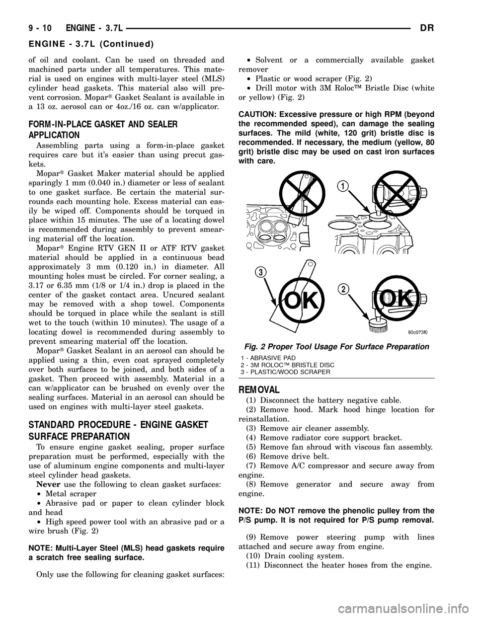
STANDARD PROCEDURE - ENGINE GASKET
SURFACE PREPARATION
To ensure engine gasket sealing, proper surface
preparation must be performed, especially with the
use of aluminum engine components and multi-layer
steel cylinder head gaskets.
Neveruse the following to clean gasket surfaces:
²Metal scraper
²Abrasive pad or paper to clean cylinder block
and head
²High speed power tool with an abrasive pad or a
wire brush (Fig. 2)
NOTE: Multi-Layer Steel (MLS) head gaskets require
a scratch free sealing surface.
Only use the following for cleaning gasket surfaces:²Solvent or a commercially available gasket
remover
²Plastic or wood scraper (Fig. 2)
²Drill motor with 3M RolocŸ Bristle Disc (white
or yellow) (Fig. 2)
CAUTION: Excessive pressure or high RPM (beyond
the recommended speed), can damage the sealing
surfaces. The mild (white, 120 grit) bristle disc is
recommended. If necessary, the medium (yellow, 80
grit) bristle disc may be used on cast iron surfaces
with care.
REMOVAL
(1) Disconnect the battery negative cable.
(2) Remove hood. Mark hood hinge location for
reinstallation.
(3) Remove air cleaner assembly.
(4) Remove radiator core support bracket.
(5) Remove fan shroud with viscous fan assembly.
(6) Remove drive belt.
(7) Remove A/C compressor and secure away from
engine.
(8) Remove generator and secure away from
engine.
NOTE: Do NOT remove the phenolic pulley from the
P/S pump. It is not required for P/S pump removal.
(9) Remove power steering pump with lines
attached and secure away from engine.
(10) Drain cooling system.
(11) Disconnect the heater hoses from the engine.
Fig. 2 Proper Tool Usage For Surface Preparation
1 - ABRASIVE PAD
2 - 3M ROLOCŸ BRISTLE DISC
3 - PLASTIC/WOOD SCRAPER
9 - 10 ENGINE - 3.7LDR
ENGINE - 3.7L (Continued)
Page 1235 of 2627
(17) Connect the engine to body ground straps at
the left side of the cowl.
(18) Install the intake manifold.
(19) Install the engine oil dipstick tube.
(20) Install the power brake booster vacuum hose.
(21) Install the breather hoses.
(22) Install the PCV hose.
(23) Install the fuel rail.
(24) Install the coil over plugs.
(25) Connect the engine wiring harness at the fol-
lowing points:
²Intake air temperature (IAT) sensor
²Fuel Injectors
²Throttle Position (TPS) Switch
²Idle Air Control (IAC) Motor
²Engine Oil Pressure Switch
²Engine Coolant Temperature (ECT) Sensor
²Manifold Absolute Pressure MAP) Sensor
²Camshaft Position (CMP) Sensor
²Coil Over Plugs
²Crankshaft Position Sensor
(26) Reinstall the radiator/cooling module assem-
bly.
(27) Connect lower radiator hose.
(28) Connect upper radiator hose.
(29) Connect throttle and speed control cables.
(30) Install the heater hose assembly.
(31) Install coolant recovery bottle.
(32) Install the power steering pump.
(33) Install the generator.
(34) Install the A/C compressor.
(35) Install the drive belt.
(36) Install the fan shroud with the viscous fan
assembly.
(37) Install the radiator core support bracket.
(38) Install the air cleaner assembly.
(39) Refill the engine cooling system.
(40) Recharge the air conditioning.
(41) Install the hood.
(42) Check and fill engine oil.
(43) Connect the battery negative cable.
(44) Start the engine and check for leaks.SPECIFICATIONS
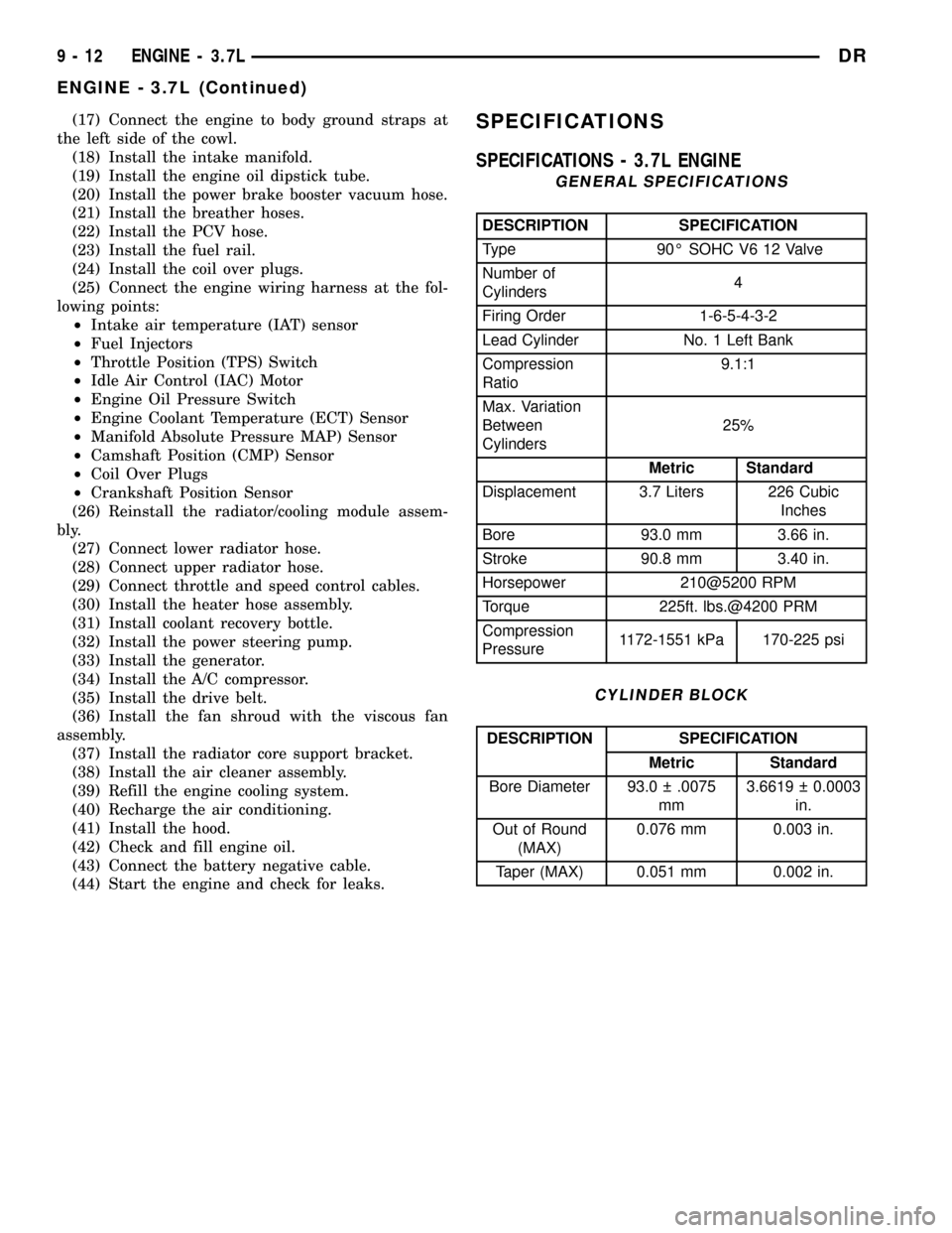
SPECIFICATIONS - 3.7L ENGINE
GENERAL SPECIFICATIONS
DESCRIPTION SPECIFICATION
Type 90É SOHC V6 12 Valve
Number of
Cylinders4
Firing Order 1-6-5-4-3-2
Lead Cylinder No. 1 Left Bank
Compression
Ratio9.1:1
Max. Variation
Between
Cylinders25%
Metric Standard
Displacement 3.7 Liters 226 Cubic
Inches
Bore 93.0 mm 3.66 in.
Stroke 90.8 mm 3.40 in.
Horsepower 210@5200 RPM
Torque 225ft. lbs.@4200 PRM
Compression
Pressure1172-1551 kPa 170-225 psi
CYLINDER BLOCK
DESCRIPTION SPECIFICATION
Metric Standard
Bore Diameter 93.0 .0075
mm3.6619 0.0003
in.
Out of Round
(MAX)0.076 mm 0.003 in.
Taper (MAX) 0.051 mm 0.002 in.
9 - 12 ENGINE - 3.7LDR
ENGINE - 3.7L (Continued)
Page 1256 of 2627

(6) Air ingested into oil due to broken or cracked
oil pump pick up.
(7) Worn valve guides.
(8) Rocker arm ears contacting valve spring
retainer.
(9) Rocker arm loose, adjuster stuck or at maxi-
mum extension and still leaves lash in the system.
(10) Oil leak or excessive cam bore wear in cylin-
der head.
(11) Faulty lash adjuster.
a. Check lash adjusters for sponginess while
installed in cylinder head and cam on camshaft at
base circle. Depress part of rocker arm over adjuster.
Normal adjusters should feel very firm. Spongy
adjusters can be bottomed out easily.
b. Remove suspected lash adjusters, and replace.
c. Before installation, make sure adjusters are at
least partially full of oil. This can be verified by little
or no plunger travel when lash adjuster is depressed.
REMOVAL
(1) Disconnect battery negative cable.
(2) Raise the vehicle on a hoist.
(3) Disconnect the exhaust pipe at the right side
exhaust manifold.
(4) Drain the engine coolant(Refer to 7 - COOL-
ING - STANDARD PROCEDURE).
(5) Lower the vehicle.
(6) Remove the intake manifold(Refer to 9 -
ENGINE/MANIFOLDS/INTAKE MANIFOLD -
REMOVAL).
(7) Remove the cylinder head cover(Refer to 9 -
ENGINE/CYLINDER HEAD - REMOVAL).
(8) Remove the fan shroud(Refer to 7 - COOLING/
ENGINE/RADIATOR FAN - REMOVAL).
(9) Remove oil fill housing from cylinder head.
(10) Remove accessory drive belt(Refer to 7 -
COOLING/ACCESSORY DRIVE/DRIVE BELTS -
REMOVAL).
(11) Rotate the crankshaft until the damper timing
mark is aligned with TDC indicator mark.
(12) Verify the V6 mark on the camshaft sprocket
is at the 12 o'clock position. Rotate the crankshaft
one turn if necessary.
(13) Remove the crankshaft damper(Refer to 9 -
ENGINE/ENGINE BLOCK/VIBRATION DAMPER -
REMOVAL).
(14) Remove the timing chain cover(Refer to 9 -
ENGINE/VALVE TIMING/TIMING BELT / CHAIN
COVER(S) - REMOVAL).
(15) Lock the secondary timing chains to the idler
sprocket using Special Tool 8429 Timing Chain Hold-
ing Fixture.NOTE: Mark the secondary timing chain prior to
removal to aid in installation.
(16) Mark the secondary timing chain, one link on
each side of the V6 mark on the camshaft drive gear.
(17) Remove the right side secondary chain ten-
sioner(Refer to 9 - ENGINE/VALVE TIMING/TIM-
ING BELT/CHAIN AND SPROCKETS - REMOVAL).
(18) Remove the cylinder head access plug.
(19) Remove the right side secondary chain
guide(Refer to 9 - ENGINE/VALVE TIMING/TIMING
BELT/CHAIN AND SPROCKETS - REMOVAL).
CAUTION: The nut on the right side camshaft
sprocket should not be removed for any reason, as
the sprocket and camshaft sensor target wheel is
serviced as an assembly. If the nut was removed,
torque nut to 5 N´m (44 in. lbs.).
(20) Remove the retaining bolt and the camshaft
drive gear.
CAUTION: Do not allow the engine to rotate. severe
damage to the valve train can occur.
CAUTION: Do not overlook the four smaller bolts at
the front of the cylinder head. Do not attempt to
remove the cylinder head without removing these
four bolts.
CAUTION: Do not hold or pry on the camshaft tar-
get wheel for any reason. A damaged target wheel
can result in a vehicle no start condition.
NOTE: The cylinder head is attached to the cylinder
block with twelve bolts.
(21) Remove the cylinder head retaining bolts.
(22) Remove the cylinder head and gasket. Discard
the gasket.
CAUTION: Do not lay the cylinder head on its gas-
ket sealing surface, do to the design of the cylinder
head gasket any distortion to the cylinder head
sealing surface may prevent the gasket from prop-
erly sealing resulting in leaks.
DRENGINE - 3.7L 9 - 33
CYLINDER HEAD - RIGHT (Continued)
Page 1287 of 2627

DIAGNOSIS AND TESTING
DIAGNOSIS AND TESTING - ENGINE OIL LEAK
Begin with a thorough visual inspection of the
engine, particularly at the area of the suspected leak.
If an oil leak source is not readily identifiable, the
following steps should be followed:
(1) Do not clean or degrease the engine at this
time because some solvents may cause rubber to
swell, temporarily stopping the leak.
(2) Add an oil soluble dye (use as recommended by
manufacturer). Start the engine and let idle for
approximately 15 minutes. Check the oil dipstick to
make sure the dye is thoroughly mixed as indicated
with a bright yellow color under a black light.
(3) Using a black light, inspect the entire engine
for fluorescent dye, particularly at the suspected area
of oil leak. If the oil leak is found and identified,
repair per service manual instructions.
(4) If dye is not observed, drive the vehicle at var-
ious speeds for approximately 24 km (15 miles), and
repeat inspection.If the oil leak source is not posi-
tively identified at this time, proceed with the air
leak detection test method.
Air Leak Detection Test Method
(1) Disconnect the breather cap to air cleaner hose
at the breather cap end. Cap or plug breather cap
nipple.
(2) Remove the PCV valve from the cylinder head
cover. Cap or plug the PCV valve grommet.
(3) Attach an air hose with pressure gauge and
regulator to the dipstick tube.
CAUTION: Do not subject the engine assembly to
more than 20.6 kPa (3 PSI) of test pressure.
(4) Gradually apply air pressure from 1 psi to 2.5
psi maximum while applying soapy water at the sus-
pected source. Adjust the regulator to the suitable
test pressure that provide the best bubbles which
will pinpoint the leak source. If the oil leak is
detected and identified, repair per service manual
procedures.
(5) If the leakage occurs at the rear oil seal area,
refer to the section, Inspection for Rear Seal Area
Leak.
(6) If no leaks are detected, turn off the air supply
and remove the air hose and all plugs and caps.
Install the PCV valve and breather cap hose.(7) Clean the oil off the suspect oil leak area using
a suitable solvent. Drive the vehicle at various
speeds approximately 24 km (15 miles). Inspect the
engine for signs of an oil leak by using a black light.
INSPECTION FOR REAR SEAL AREA LEAKS
Since it is sometimes difficult to determine the
source of an oil leak in the rear seal area of the
engine, a more involved inspection is necessary. The
following steps should be followed to help pinpoint
the source of the leak.
If the leakage occurs at the crankshaft rear oil seal
area:
(1) Disconnect the battery.
(2) Raise the vehicle.
(3) Remove torque converter or clutch housing
cover and inspect rear of block for evidence of oil.
Use a black light to check for the oil leak:
(a) Circular spray pattern generally indicates
seal leakage or crankshaft damage.
(b) Where leakage tends to run straight down,
possible causes are a porous block, distributor seal,
camshaft bore cup plugs oil galley pipe plugs, oil
filter runoff, and main bearing cap to cylinder
block mating surfaces.
(4) If no leaks are detected, pressurize the crank-
case as outlined in the, Inspection (Engine oil Leaks
in general)
CAUTION: Do not exceed 20.6 kPa (3 psi).
(5) If the leak is not detected, very slowly turn the
crankshaft and watch for leakage. If a leak is
detected between the crankshaft and seal while
slowly turning the crankshaft, it is possible the
crankshaft seal surface is damaged. The seal area on
the crankshaft could have minor nicks or scratches
that can be polished out with emery cloth.
CAUTION: Use extreme caution when crankshaft
polishing is necessary to remove minor nicks and
scratches. The crankshaft seal flange is especially
machined to complement the function of the rear oil
seal.
(6) For bubbles that remain steady with shaft
rotation, no further inspection can be done until dis-
assembled.
9 - 64 ENGINE - 3.7LDR
LUBRICATION (Continued)