1998 DODGE RAM 1500 air condition
[x] Cancel search: air conditionPage 1321 of 2627
Position both the left and right side engine mount
brackets and install the through bolts and nuts.
Tighten nuts to4X2 vehicles95 N´m (70 ft. lbs.).
4X4 vehicles102 N´m (75 ft. lbs.).
(2)4X4 vehiclesInstall locknuts onto the engine
mount brackets. Tighten locknuts to 41 N´m (30 ft.
lbs.).
(3) Remove jack from under the transmission.
(4) Remove Engine Lifting Fixture Special Tool
8347 (Fig. 4).
(5) Remove Special Tools 8400 Lifting Studs.
(6) Position generator wiring behind the oil dip-
stick tube, then install the oil dipstick tube upper
mounting bolt.
(7) Connect both left and right side body ground
straps.
(8) Install power steering pump.
(9) Connect fuel supply line quick connect fitting
(Refer to 14 - FUEL SYSTEM/FUEL DELIVERY/
QUICK CONNECT FITTING - STANDARD PROCE-
DURE).
(10) Connect the vacuum lines at the throttle body
and intake manifold.
(11) Connect engine harness at the following
points (Fig. 3):
²Intake Air Temperature (IAT) Sensor
²Idle Air Control (IAC) Motor
²Fuel Injectors
²Throttle Position (TPS) Switch
²Engine Oil Pressure Switch
²Engine Coolant Temperature (ECT) Sensor
²Manifold Absolute Pressure (MAP) Sensor
²Camshaft Position (CMP) Sensor
²Coil Over Plugs
(12) Position and install heater hoses and tubes
onto intake manifold.
(13) Install the heater hoses onto the heater core
and the engine front cover.
(14) Install generator (Refer to 8 - ELECTRICAL/
CHARGING/GENERATOR - INSTALLATION).
(15) Install A/C condenser (Refer to 24 - HEATING
& AIR CONDITIONING/PLUMBING/A/C CON-
DENSER - INSTALLATION), radiator (Refer to 7 -
COOLING/ENGINE/RADIATOR - INSTALLATION)
and transmission oil cooler.
(16) Connect radiator upper and lower hoses.
(17) Connect the transmission oil cooler lines to
the radiator.
(18) Install accessory drive belt (Refer to 7 -
COOLING/ACCESSORY DRIVE/DRIVE BELTS -INSTALLATION), fan assembly and shroud (Refer to
7 - COOLING/ENGINE/FAN DRIVE VISCOUS
CLUTCH - INSTALLATION).
(19) Install A/C compressor (Refer to 24 - HEAT-
ING & AIR CONDITIONING/PLUMBING/A/C COM-
PRESSOR - INSTALLATION).
(20) Install both breathers. Connect tube to both
crankcase breathers (Fig. 2).
(21) Connect throttle and speed control cables.
(22) Install throttle body resonator assembly and
air inlet hose. Tighten clamps 4 N´m (35 in. lbs.).
(23) Raise vehicle.
(24) Install transmission to engine mounting bolts.
Tighten the bolts to 41 N´m (30 ft. lbs.).
(25) Install torque converter bolts (Automatic
Transmission Only).
(26) Connect crankshaft position sensor (Fig. 1).
(27)4X4 vehiclesPosition and install the axle
isolator bracket onto the axle, transmission and
engine block. Tighten bolts to specification (Refer to 9
- ENGINE - SPECIFICATIONS).
(28) Install starter (Refer to 8 - ELECTRICAL/
STARTING/STARTER MOTOR - INSTALLATION).
CAUTION: The structural cover requires a specific
torque sequence. Failure to follow this sequence
may cause severe damage to the cover.
(29) Install structural cover (Refer to 9 - ENGINE/
ENGINE BLOCK/STRUCTURAL COVER - INSTAL-
LATION).
(30) Install exhaust crossover pipe.
(31) Install engine block heater power cable, If
equipped.
(32)4X4 vehiclesConnect axle vent tube to left
side engine mount.
(33) Lower vehicle.
(34) Check and fill engine oil.
(35) Recharge the A/C system (Refer to 24 - HEAT-
ING & AIR CONDITIONING/PLUMBING/REFRIG-
ERANT - STANDARD PROCEDURE).
(36) Refill the engine cooling system (Refer to 7 -
COOLING - STANDARD PROCEDURE).
(37) Install the battery tray and battery.
(38) Connect the battery positive and negative
cables.
(39) Start the engine and check for leaks.
9 - 98 ENGINE - 4.7LDR
ENGINE - 4.7L (Continued)
Page 1345 of 2627
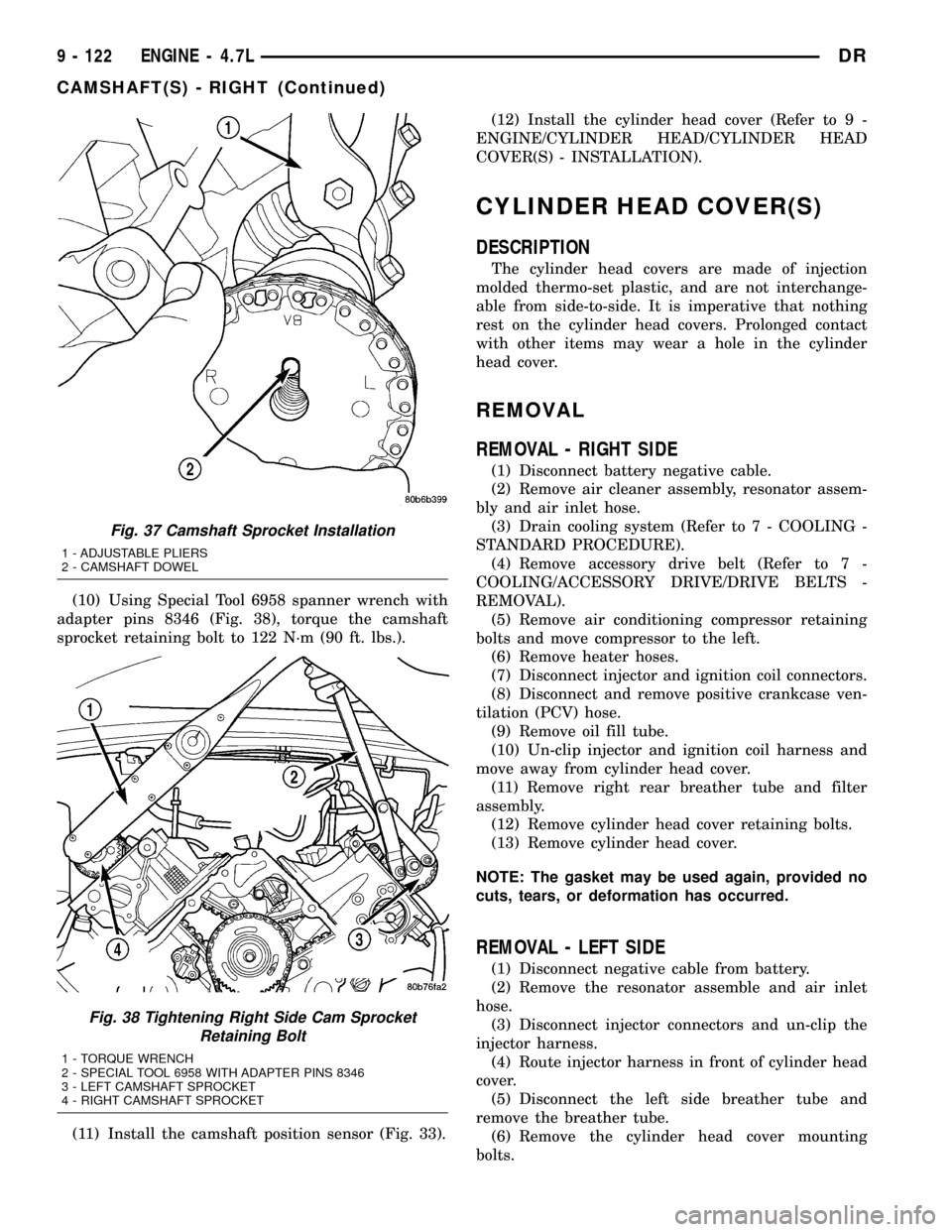
(10) Using Special Tool 6958 spanner wrench with
adapter pins 8346 (Fig. 38), torque the camshaft
sprocket retaining bolt to 122 N´m (90 ft. lbs.).
(11) Install the camshaft position sensor (Fig. 33).(12) Install the cylinder head cover (Refer to 9 -
ENGINE/CYLINDER HEAD/CYLINDER HEAD
COVER(S) - INSTALLATION).
CYLINDER HEAD COVER(S)
DESCRIPTION
The cylinder head covers are made of injection
molded thermo-set plastic, and are not interchange-
able from side-to-side. It is imperative that nothing
rest on the cylinder head covers. Prolonged contact
with other items may wear a hole in the cylinder
head cover.
REMOVAL
REMOVAL - RIGHT SIDE
(1) Disconnect battery negative cable.
(2) Remove air cleaner assembly, resonator assem-
bly and air inlet hose.
(3) Drain cooling system (Refer to 7 - COOLING -
STANDARD PROCEDURE).
(4) Remove accessory drive belt (Refer to 7 -
COOLING/ACCESSORY DRIVE/DRIVE BELTS -
REMOVAL).
(5) Remove air conditioning compressor retaining
bolts and move compressor to the left.
(6) Remove heater hoses.
(7) Disconnect injector and ignition coil connectors.
(8) Disconnect and remove positive crankcase ven-
tilation (PCV) hose.
(9) Remove oil fill tube.
(10) Un-clip injector and ignition coil harness and
move away from cylinder head cover.
(11) Remove right rear breather tube and filter
assembly.
(12) Remove cylinder head cover retaining bolts.
(13) Remove cylinder head cover.
NOTE: The gasket may be used again, provided no
cuts, tears, or deformation has occurred.
REMOVAL - LEFT SIDE
(1) Disconnect negative cable from battery.
(2) Remove the resonator assemble and air inlet
hose.
(3) Disconnect injector connectors and un-clip the
injector harness.
(4) Route injector harness in front of cylinder head
cover.
(5) Disconnect the left side breather tube and
remove the breather tube.
(6) Remove the cylinder head cover mounting
bolts.
Fig. 37 Camshaft Sprocket Installation
1 - ADJUSTABLE PLIERS
2 - CAMSHAFT DOWEL
Fig. 38 Tightening Right Side Cam Sprocket
Retaining Bolt
1 - TORQUE WRENCH
2 - SPECIAL TOOL 6958 WITH ADAPTER PINS 8346
3 - LEFT CAMSHAFT SPROCKET
4 - RIGHT CAMSHAFT SPROCKET
9 - 122 ENGINE - 4.7LDR
CAMSHAFT(S) - RIGHT (Continued)
Page 1346 of 2627
(7) Remove cylinder head cover and gasket.
NOTE: The gasket may be used again, provided no
cuts, tears, or deformation has occurred.
CLEANING
Clean cylinder head cover gasket surface.
Clean head rail, if necessary.
INSTALLATION
INSTALLATION - RIGHT SIDE
CAUTION: Do not use harsh cleaners to clean the
cylinder head covers. Severe damage to covers
may occur.
(1) Clean cylinder head cover and both sealing sur-
faces. Inspect and replace gasket as necessary.
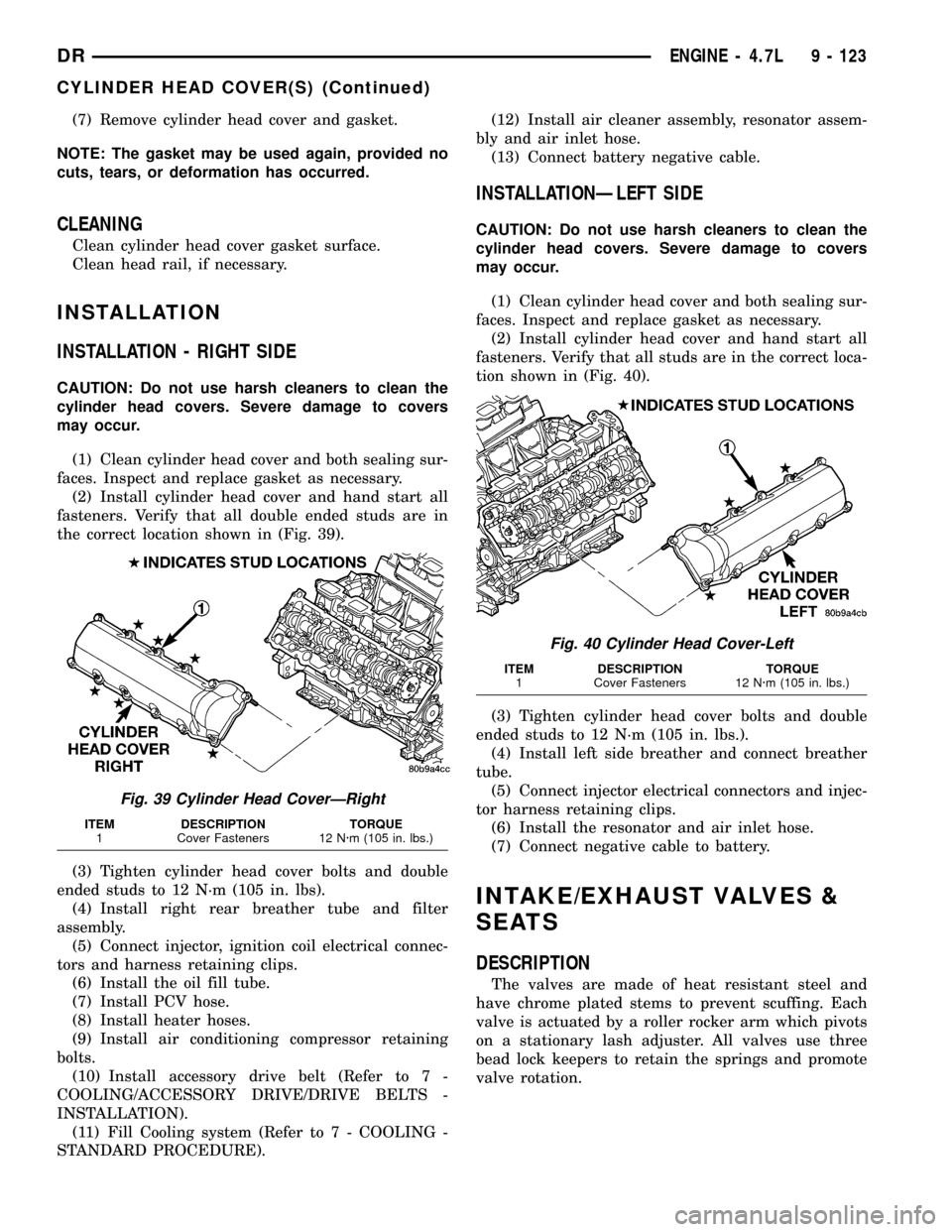
(2) Install cylinder head cover and hand start all
fasteners. Verify that all double ended studs are in
the correct location shown in (Fig. 39).
(3) Tighten cylinder head cover bolts and double
ended studs to 12 N´m (105 in. lbs).
(4) Install right rear breather tube and filter
assembly.
(5) Connect injector, ignition coil electrical connec-
tors and harness retaining clips.
(6) Install the oil fill tube.
(7) Install PCV hose.
(8) Install heater hoses.
(9) Install air conditioning compressor retaining
bolts.
(10) Install accessory drive belt (Refer to 7 -
COOLING/ACCESSORY DRIVE/DRIVE BELTS -
INSTALLATION).
(11) Fill Cooling system (Refer to 7 - COOLING -
STANDARD PROCEDURE).(12) Install air cleaner assembly, resonator assem-
bly and air inlet hose.
(13) Connect battery negative cable.
INSTALLATIONÐLEFT SIDE
CAUTION: Do not use harsh cleaners to clean the
cylinder head covers. Severe damage to covers
may occur.
(1) Clean cylinder head cover and both sealing sur-
faces. Inspect and replace gasket as necessary.
(2) Install cylinder head cover and hand start all
fasteners. Verify that all studs are in the correct loca-
tion shown in (Fig. 40).
(3) Tighten cylinder head cover bolts and double
ended studs to 12 N´m (105 in. lbs.).
(4) Install left side breather and connect breather
tube.
(5) Connect injector electrical connectors and injec-
tor harness retaining clips.
(6) Install the resonator and air inlet hose.
(7) Connect negative cable to battery.
INTAKE/EXHAUST VALVES &
SEATS
DESCRIPTION
The valves are made of heat resistant steel and
have chrome plated stems to prevent scuffing. Each
valve is actuated by a roller rocker arm which pivots
on a stationary lash adjuster. All valves use three
bead lock keepers to retain the springs and promote
valve rotation.
Fig. 39 Cylinder Head CoverÐRight
ITEM DESCRIPTION TORQUE
1 Cover Fasteners 12 N´m (105 in. lbs.)
Fig. 40 Cylinder Head Cover-Left
ITEM DESCRIPTION TORQUE
1 Cover Fasteners 12 N´m (105 in. lbs.)
DRENGINE - 4.7L 9 - 123
CYLINDER HEAD COVER(S) (Continued)
Page 1351 of 2627
ENGINE BLOCK
DESCRIPTION
The cylinder block is made of cast iron. The block
is a closed deck design with the left bank forward. To
provide high rigidity and improved NVH an
enhanced compacted graphite bedplate is bolted to
the block. The block design allows coolant flow
between the cylinders bores, and an internal coolant
bypass to a single poppet inlet thermostat is included
in the cast aluminum front cover.
STANDARD PROCEDURE - CYLINDER BORE
HONING
Before honing, stuff plenty of clean shop towels
under the bores and over the crankshaft to keep
abrasive materials from entering the crankshaft
area.
(1) Used carefully, the Cylinder Bore Sizing Hone
C-823, equipped with 220 grit stones, is the best tool
for this job. In addition to deglazing, it will reduce
taper and out-of-round, as well as removing light
scuffing, scoring and scratches. Usually, a few strokes
will clean up a bore and maintain the required lim-
its.
CAUTION: DO NOT use rigid type hones to remove
cylinder wall glaze.
(2) Deglazing of the cylinder walls may be done if
the cylinder bore is straight and round. Use a cylin-
der surfacing hone, Honing Tool C-3501, equipped
with 280 grit stones (C-3501-3810). about 20-60
strokes, depending on the bore condition, will be suf-
ficient to provide a satisfactory surface. Using honing
oil C-3501-3880, or a light honing oil, available from
major oil distributors.
CAUTION: DO NOT use engine or transmission oil,
mineral spirits, or kerosene.
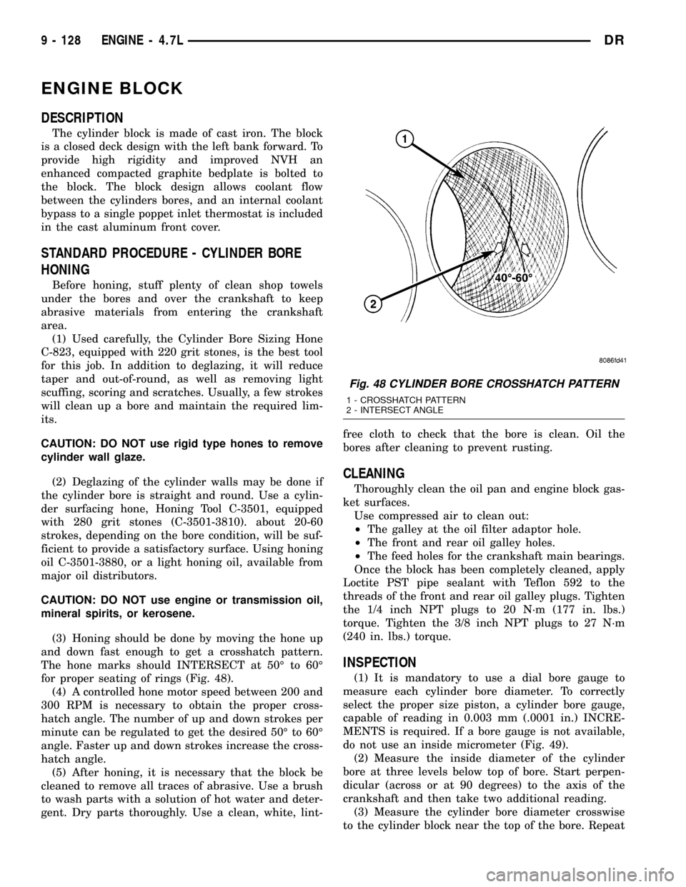
(3) Honing should be done by moving the hone up
and down fast enough to get a crosshatch pattern.
The hone marks should INTERSECT at 50É to 60É
for proper seating of rings (Fig. 48).
(4) A controlled hone motor speed between 200 and
300 RPM is necessary to obtain the proper cross-
hatch angle. The number of up and down strokes per
minute can be regulated to get the desired 50É to 60É
angle. Faster up and down strokes increase the cross-
hatch angle.
(5) After honing, it is necessary that the block be
cleaned to remove all traces of abrasive. Use a brush
to wash parts with a solution of hot water and deter-
gent. Dry parts thoroughly. Use a clean, white, lint-free cloth to check that the bore is clean. Oil the
bores after cleaning to prevent rusting.
CLEANING
Thoroughly clean the oil pan and engine block gas-
ket surfaces.
Use compressed air to clean out:
²The galley at the oil filter adaptor hole.
²The front and rear oil galley holes.
²The feed holes for the crankshaft main bearings.
Once the block has been completely cleaned, apply
Loctite PST pipe sealant with Teflon 592 to the
threads of the front and rear oil galley plugs. Tighten
the 1/4 inch NPT plugs to 20 N´m (177 in. lbs.)
torque. Tighten the 3/8 inch NPT plugs to 27 N´m
(240 in. lbs.) torque.
INSPECTION
(1) It is mandatory to use a dial bore gauge to
measure each cylinder bore diameter. To correctly
select the proper size piston, a cylinder bore gauge,
capable of reading in 0.003 mm (.0001 in.) INCRE-
MENTS is required. If a bore gauge is not available,
do not use an inside micrometer (Fig. 49).
(2) Measure the inside diameter of the cylinder
bore at three levels below top of bore. Start perpen-
dicular (across or at 90 degrees) to the axis of the
crankshaft and then take two additional reading.
(3) Measure the cylinder bore diameter crosswise
to the cylinder block near the top of the bore. Repeat
Fig. 48 CYLINDER BORE CROSSHATCH PATTERN
1 - CROSSHATCH PATTERN
2 - INTERSECT ANGLE
9 - 128 ENGINE - 4.7LDR
Page 1382 of 2627
INSTALLATION
(1) Position the oil pump onto the crankshaft and
install one oil pump retaining bolts.
(2) Position the primary timing chain tensioner
and install three retaining bolts.
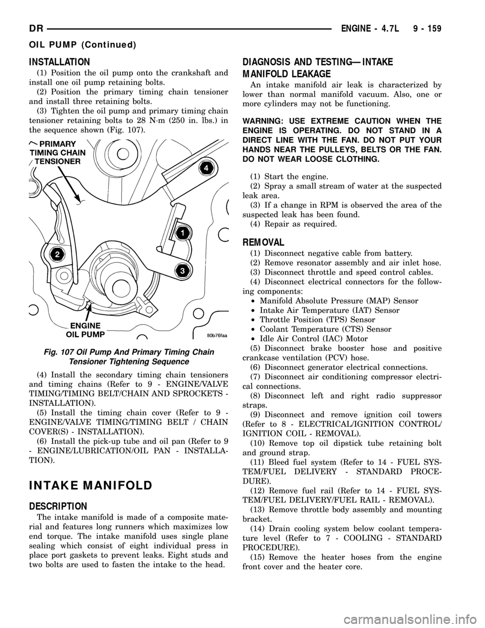
(3) Tighten the oil pump and primary timing chain
tensioner retaining bolts to 28 N´m (250 in. lbs.) in
the sequence shown (Fig. 107).
(4) Install the secondary timing chain tensioners
and timing chains (Refer to 9 - ENGINE/VALVE
TIMING/TIMING BELT/CHAIN AND SPROCKETS -
INSTALLATION).
(5) Install the timing chain cover (Refer to 9 -
ENGINE/VALVE TIMING/TIMING BELT / CHAIN
COVER(S) - INSTALLATION).
(6) Install the pick-up tube and oil pan (Refer to 9
- ENGINE/LUBRICATION/OIL PAN - INSTALLA-
TION).
INTAKE MANIFOLD
DESCRIPTION
The intake manifold is made of a composite mate-
rial and features long runners which maximizes low
end torque. The intake manifold uses single plane
sealing which consist of eight individual press in
place port gaskets to prevent leaks. Eight studs and
two bolts are used to fasten the intake to the head.
DIAGNOSIS AND TESTINGÐINTAKE
MANIFOLD LEAKAGE
An intake manifold air leak is characterized by
lower than normal manifold vacuum. Also, one or
more cylinders may not be functioning.
WARNING: USE EXTREME CAUTION WHEN THE
ENGINE IS OPERATING. DO NOT STAND IN A
DIRECT LINE WITH THE FAN. DO NOT PUT YOUR
HANDS NEAR THE PULLEYS, BELTS OR THE FAN.
DO NOT WEAR LOOSE CLOTHING.
(1) Start the engine.
(2) Spray a small stream of water at the suspected
leak area.
(3) If a change in RPM is observed the area of the
suspected leak has been found.
(4) Repair as required.
REMOVAL
(1) Disconnect negative cable from battery.
(2) Remove resonator assembly and air inlet hose.
(3) Disconnect throttle and speed control cables.
(4) Disconnect electrical connectors for the follow-
ing components:
²Manifold Absolute Pressure (MAP) Sensor
²Intake Air Temperature (IAT) Sensor
²Throttle Position (TPS) Sensor
²Coolant Temperature (CTS) Sensor
²Idle Air Control (IAC) Motor
(5) Disconnect brake booster hose and positive
crankcase ventilation (PCV) hose.
(6) Disconnect generator electrical connections.
(7) Disconnect air conditioning compressor electri-
cal connections.
(8) Disconnect left and right radio suppressor
straps.
(9) Disconnect and remove ignition coil towers
(Refer to 8 - ELECTRICAL/IGNITION CONTROL/
IGNITION COIL - REMOVAL).
(10) Remove top oil dipstick tube retaining bolt
and ground strap.
(11) Bleed fuel system (Refer to 14 - FUEL SYS-
TEM/FUEL DELIVERY - STANDARD PROCE-
DURE).
(12) Remove fuel rail (Refer to 14 - FUEL SYS-
TEM/FUEL DELIVERY/FUEL RAIL - REMOVAL).
(13) Remove throttle body assembly and mounting
bracket.
(14) Drain cooling system below coolant tempera-
ture level (Refer to 7 - COOLING - STANDARD
PROCEDURE).
(15) Remove the heater hoses from the engine
front cover and the heater core.
Fig. 107 Oil Pump And Primary Timing Chain
Tensioner Tightening Sequence
DRENGINE - 4.7L 9 - 159
OIL PUMP (Continued)
Page 1384 of 2627
EXHAUST MANIFOLD
DESCRIPTION
The exhaust manifolds are log style with a pat-
ented flow enhancing design to maximize perfor-
mance. The exhaust manifolds are made of high
silicon molybdenum cast iron. A perforated core
graphite exhaust manifold gasket is used to improve
sealing to the cylinder head. The exhaust manifolds
are covered by a three layer laminated heat shield
for thermal protection and noise reduction. The heat
shields are fastened with a torque prevailing nut
that is backed off slightly to allow for the thermal
expansion of the exhaust manifold.
REMOVAL
RIGHT EXHAUST MANIFOLD
(1) Disconnect negative cable for battery.
(2) Remove air cleaner assembly, resonator assem-
bly and air inlet hose.
(3) Remove accessory drive belt (Refer to 7 -
COOLING/ACCESSORY DRIVE/DRIVE BELTS -
REMOVAL).
(4) Remove A/C compressor (Refer to 24 - HEAT-
ING & AIR CONDITIONING/PLUMBING/A/C COM-
PRESSOR - REMOVAL).
(5) Remove A/C accumulator support bracket fas-
tener.(6) Drain coolant below heater hose level (Refer to
7 - COOLING - STANDARD PROCEDURE).
(7) Remove heater hoses at engine.
(8) Remove fasteners attaching exhaust manifold
heat shield.
(9) Remove heat shield.
(10) Remove upper exhaust manifold attaching fas-
teners.
(11) Raise vehicle on hoist.
(12) Disconnect exhaust pipe from manifold.
(13) Remove fasteners attaching starter. Move
starter aside.
(14) Remove lower exhaust manifold attaching fas-
teners.
(15) Remove exhaust manifold and gasket (Fig.
110). Manifold is removed from below the engine
compartment.
DRENGINE - 4.7L 9 - 161
Page 1406 of 2627
DIAGNOSIS AND TESTING
DIAGNOSIS AND TESTING - ENGINE
DIAGNOSIS - INTRODUCTION
Engine diagnosis is helpful in determining the
causes of malfunctions not detected and remedied by
routine maintenance.
These malfunctions may be classified as either per-
formance (e.g., engine idles rough and stalls) or
mechanical (e.g., a strange noise).
(Refer to 9 - ENGINE - DIAGNOSIS AND TEST-
ING) - PERFORMANCE and (Refer to 9 - ENGINE -
DIAGNOSIS AND TESTING)ÐMECHANICAL for
possible causes and corrections of malfunctions.
(Refer to 14 - FUEL SYSTEM/FUEL DELIVERY -
DIAGNOSIS AND TESTING) and (Refer to 14 -
FUEL SYSTEM/FUEL INJECTION - DIAGNOSIS
AND TESTING) for the fuel system diagnosis.Additional tests and diagnostic procedures may be
necessary for specific engine malfunctions that can
not be isolated with the Service Diagnosis charts.
Information concerning additional tests and diagno-
sis is provided within the following diagnosis:
²Cylinder Compression Pressure Test (Refer to 9 -
ENGINE - DIAGNOSIS AND TESTING).
²Cylinder Combustion Pressure Leakage Test
(Refer to 9 - ENGINE - DIAGNOSIS AND TEST-
ING).
²Engine Cylinder Head Gasket Failure Diagnosis
(Refer to 9 - ENGINE/CYLINDER HEAD - DIAGNO-
SIS AND TESTING).
²Intake Manifold Leakage Diagnosis (Refer to 9 -
ENGINE/MANIFOLDS/INTAKE MANIFOLD -
DIAGNOSIS AND TESTING).
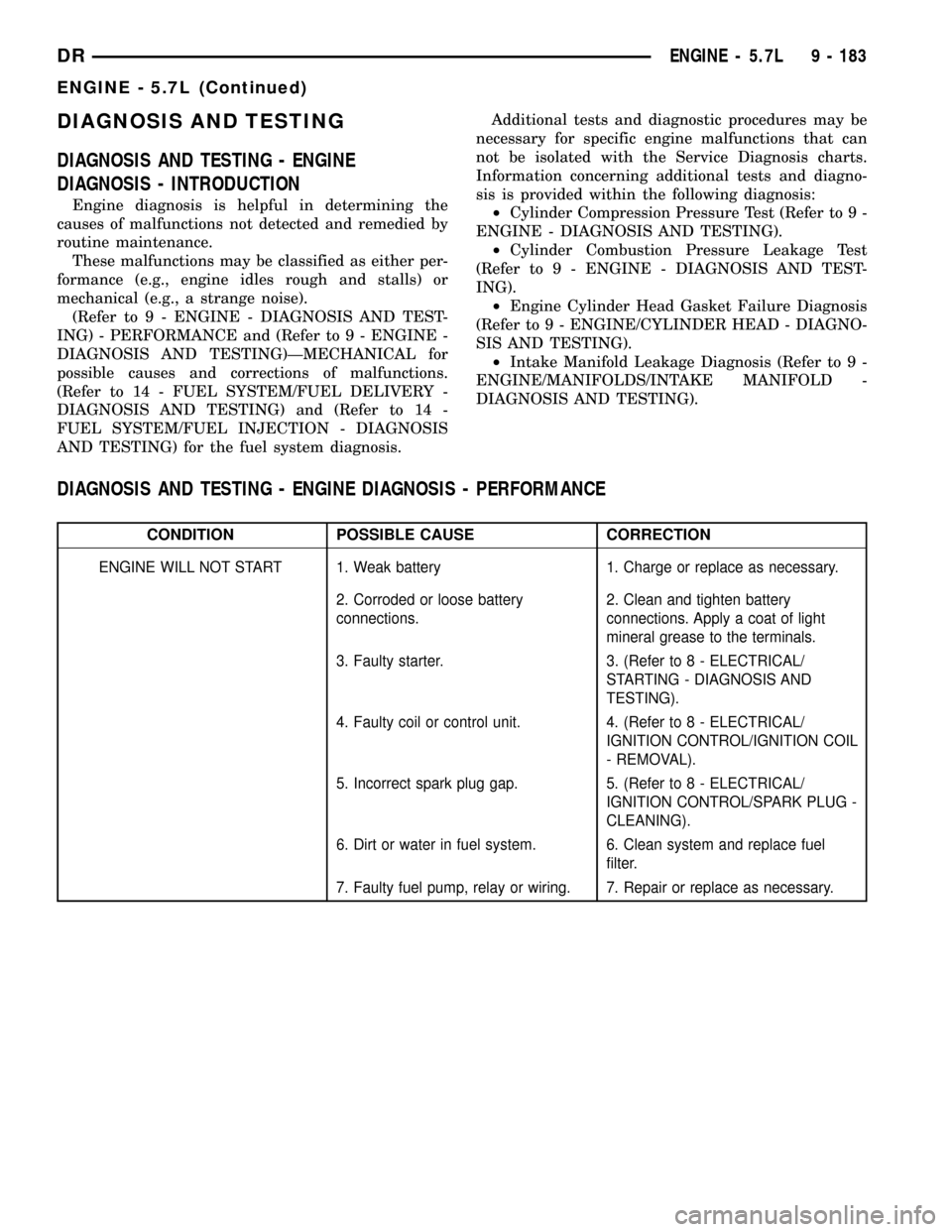
DIAGNOSIS AND TESTING - ENGINE DIAGNOSIS - PERFORMANCE
CONDITION POSSIBLE CAUSE CORRECTION
ENGINE WILL NOT START 1. Weak battery 1. Charge or replace as necessary.
2. Corroded or loose battery
connections.2. Clean and tighten battery
connections. Apply a coat of light
mineral grease to the terminals.
3. Faulty starter. 3. (Refer to 8 - ELECTRICAL/
STARTING - DIAGNOSIS AND
TESTING).
4. Faulty coil or control unit. 4. (Refer to 8 - ELECTRICAL/
IGNITION CONTROL/IGNITION COIL
- REMOVAL).
5. Incorrect spark plug gap. 5. (Refer to 8 - ELECTRICAL/
IGNITION CONTROL/SPARK PLUG -
CLEANING).
6. Dirt or water in fuel system. 6. Clean system and replace fuel
filter.
7. Faulty fuel pump, relay or wiring. 7. Repair or replace as necessary.
DRENGINE - 5.7L 9 - 183
ENGINE - 5.7L (Continued)
Page 1407 of 2627
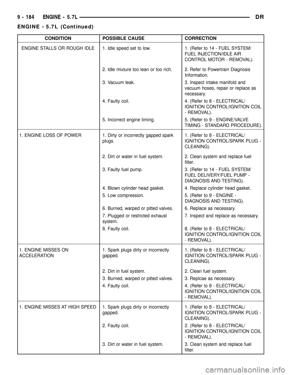
CONDITION POSSIBLE CAUSE CORRECTION
ENGINE STALLS OR ROUGH IDLE 1. Idle speed set to low. 1. (Refer to 14 - FUEL SYSTEM/
FUEL INJECTION/IDLE AIR
CONTROL MOTOR - REMOVAL).
2. Idle mixture too lean or too rich. 2. Refer to Powertrain Diagnosis
Information.
3. Vacuum leak. 3. Inspect intake manifold and
vacuum hoses, repair or replace as
necessary.
4. Faulty coil. 4. (Refer to 8 - ELECTRICAL/
IGNITION CONTROL/IGNITION COIL
- REMOVAL).
5. Incorrect engine timing. 5. (Refer to 9 - ENGINE/VALVE
TIMING - STANDARD PROCEDURE).
1. ENGINE LOSS OF POWER 1. Dirty or incorrectly gapped spark
plugs.1. (Refer to 8 - ELECTRICAL/
IGNITION CONTROL/SPARK PLUG -
CLEANING).
2. Dirt or water in fuel system. 2. Clean system and replace fuel
filter.
3. Faulty fuel pump. 3. (Refer to 14 - FUEL SYSTEM/
FUEL DELIVERY/FUEL PUMP -
DIAGNOSIS AND TESTING).
4. Blown cylinder head gasket. 4. Replace cylinder head gasket.
5. Low compression. 5. (Refer to 9 - ENGINE -
DIAGNOSIS AND TESTING).
6. Burned, warped or pitted valves. 6. Replace as necessary.
7. Plugged or restricted exhaust
system.7. Inspect and replace as necessary.
8. Faulty coil. 8. (Refer to 8 - ELECTRICAL/
IGNITION CONTROL/IGNITION COIL
- REMOVAL).
1. ENGINE MISSES ON
ACCELERATION1. Spark plugs dirty or incorrectly
gapped.1. (Refer to 8 - ELECTRICAL/
IGNITION CONTROL/SPARK PLUG -
CLEANING).
2. Dirt in fuel system. 2. Clean fuel system.
3. Burned, warped or pitted valves. 3. Replcae as necessary.
4. Faulty coil. 4. (Refer to 8 - ELECTRICAL/
IGNITION CONTROL/IGNITION COIL
- REMOVAL).
1. ENGINE MISSES AT HIGH SPEED 1. Spark plugs dirty or incorrectly
gapped.1. (Refer to 8 - ELECTRICAL/
IGNITION CONTROL/SPARK PLUG -
CLEANING).
2. Faulty coil. 2. (Refer to 8 - ELECTRICAL/
IGNITION CONTROL/IGNITION COIL
- REMOVAL).
3. Dirt or water in fuel system. 3. Clean system and replace fuel
filter.
9 - 184 ENGINE - 5.7LDR
ENGINE - 5.7L (Continued)