1998 DODGE RAM 1500 Front axle
[x] Cancel search: Front axlePage 464 of 2627

(6) Note reading on ammeter and compare reading
to free running test maximum amperage draw. Refer
to Specifications for starter motor free running test
maximum amperage draw specifications.
(7) If ammeter reading exceeds maximum amper-
age draw specification, replace faulty starter motor
assembly.
STARTER SOLENOID
This test can only be performed with starter motor
removed from vehicle.
(1) Remove starter motor from vehicle. Refer to
Starter Motor Removal and Installation.
(2) Disconnect wire from solenoid field coil termi-
nal.
(3) Check for continuity between solenoid terminal
and solenoid field coil terminal with a continuity
tester (Fig. 7). There should be continuity. If OK, go
to Step 4. If not OK, replace faulty starter motor
assembly.
(4) Check for continuity between solenoid terminal
and solenoid case (Fig. 8). There should be continuity.
If not OK, replace faulty starter motor assembly.REMOVAL
3.7L / 4.7L
(1) Disconnect and isolate negative battery cable.
(2) Raise and support vehicle.
(3) Note: If equipped with 4WD and certain trans-
missions, a support bracket is used between front
axle and side of transmission. Remove 2 support
bracket bolts at transmission. Pry support bracket
slightly to gain access to lower starter mounting bolt.
(4) Remove 1 bolt and 1 nut if equipped with a
manual transmission (Fig. 9).
(5) Remove 2 bolts if equipped with an automatic
transmission (Fig. 10).
(6) Move starter motor towards front of vehicle far
enough for nose of starter pinion housing to clear
housing. Always support starter motor during this
process, do not let starter motor hang from wire har-
ness.
(7) Tilt nose downwards and lower starter motor
far enough to access and remove nut that secures
battery positive cable wire harness connector eyelet
to solenoid battery terminal stud. Do not let starter
motor hang from wire harness.
(8) Remove battery positive cable wire harness
connector eyelet from solenoid battery terminal stud.
(9) Disconnect battery positive cable wire harness
connector from solenoid terminal connector recepta-
cle.
(10) Remove starter motor.
Fig. 7 CONTINUITY BETWEEN SOLENOID AND
FIELD COIL TERMINALS - TYPICAL
1 - OHMMETER
2 - SOLENOID TERMINAL
3 - FIELD COIL TERMINAL
Fig. 8 CONTINUITY BETWEEN SOLENOID
TERMINAL AND CASE - TYPICAL
1 - SOLENOID TERMINAL
2 - OHMMETER
3 - SOLENOID
Fig. 9 STARTER R/I - 3.7L/4.7L - MAN. TRANS.
1 - EYELET TERMINAL
2 - NUT
3 - BRACKET
4 - STUD
5 - STARTER MOTOR
6 - LOCK WASHER
7 - WIRE HARNESS CONNECTOR
8 - NUT
9 - SCREW AND WASHER (2)
DRSTARTING 8F - 33
STARTER MOTOR (Continued)
Page 465 of 2627

5.7L Gas
(1) Disconnect and isolate negative battery cable.
(2) Raise and support vehicle.
(3) Note: If equipped with 4WD and certain trans-
missions, a support bracket is used between front
axle and side of transmission. Remove 2 support
bracket bolts at transmission. Pry support bracket
slightly to gain access to lower starter mounting bolt.
(4) Remove 2 mounting bolts (Fig. 11).
(5) Move starter motor towards front of vehicle far
enough for nose of starter pinion housing to clear
housing. Always support starter motor during this
process, do not let starter motor hang from wire har-
ness.
(6) Tilt nose downwards and lower starter motor
far enough to access and remove nut that secures
battery positive cable wire harness connector eyelet
to solenoid battery terminal stud. Do not let starter
motor hang from wire harness.
(7) Remove battery positive cable wire harness
connector eyelet from solenoid battery terminal stud.
(8) Disconnect battery positive cable wire harness
connector from solenoid terminal connector recepta-
cle.
(9) Remove starter motor.
5.9L Diesel
(1) Disconnect and isolate both negative battery
cables at both batteries.
(2) Raise and support vehicle.
(3) Remove 3 starter mounting bolts (Fig. 12).(4) Move starter motor towards front of vehicle far
enough for nose of starter pinion housing to clear
housing. Always support starter motor during this
process. Do not let starter motor hang from wire har-
ness.
(5) Tilt nose downwards and lower starter motor
far enough to access and remove nuts securing
starter wiring harness to starter (Fig. 13). Do not let
starter motor hang from wire harness.
(6) Remove starter motor from engine. Note: Cer-
tain diesel engines use an aluminum spacer (Fig. 12).
Note position and orientation of spacer before
removal.
INSTALLATION
3.7L / 4.7L
(1) Connect solenoid wire to starter motor (snaps
on).
(2) Position battery cable to solenoid stud. Install
and tighten battery cable eyelet nut. Refer to Torque
Specifications. Do not allow starter motor to hang
from wire harness.
(3) Position starter motor to transmission.
(4) If equipped with automatic transmission, slide
cooler tube bracket into position.
(5) Install and tighten both bolts (auto. trans.), or
1 nut and 1 bolt (man. trans.). Refer to Torque Spec-
ifications.
(6) Lower vehicle.
(7) Connect negative battery cable.
Fig. 10 STARTER R/I - 3.7L/4.7L - AUTO. TRANS.
1 - EYELET TERMINAL
2 - NUT
3 - SCREW AND WASHER (2)
4 - STARTER MOTOR
5 - WIRE HARNESS CONNECTOR
Fig. 11 STARTER R/I - 5.7L
1 - STARTER MOTOR
2 - MOUNTING BOLTS
8F - 34 STARTINGDR
STARTER MOTOR (Continued)
Page 1281 of 2627

FRONT MOUNT
REMOVAL
2WD
(1) Disconnect the negative cable from the battery.
CAUTION: Remove the viscous fan before raising
engine. Failure to do so may cause damage to the
fan blade, fan clutch and fan shroud.
(2) Remove the viscous fan (Refer to 7 - COOL-
ING/ENGINE/FAN DRIVE VISCOUS CLUTCH -
REMOVAL).
(3) Raise the vehicle.
(4) Remove the engine oil filter.
(5) Remove the oil drain trough.
(6)
Support the engine with a suitable jack and a
block of wood across the full width of the engine oil pan.
(7) Support the front axle with a suitable jack.
(8) Remove the (4) bolts that attach the engine
mounts to the front axle.
(9) Remove the (3) bolts that attach the front axle
to the left engine bracket.
(10) Lower the front axle.
(11) Remove the through bolts(12) Raise the engine far enough to be able to
remove the left and right engine mounts.
(13) Remove the (8) mount to engine attaching
bolts
(14) Remove the engine mounts.
4WD
(1) Disconnect the negative cable from the battery.
CAUTION: Remove the viscous fan before raising
engine. Failure to do so may cause damage to the
fan blade, fan clutch and fan shroud.
(2) Remove the viscous fan (Refer to 7 - COOL-
ING/ENGINE/FAN DRIVE VISCOUS CLUTCH -
REMOVAL).
(3) Raise the vehicle.
(4) Remove the skid plate.
(5) Remove the front crossmember.
(6) Remove the engine oil filter.
(7) Remove the oil drain trough.
(8) Support the engine with a suitable jack and a
block of wood across the full width of the engine oil
pan.
(9) Support the front axle with a suitable jack.
(10) Remove the (4) bolts that attach the engine
mounts to the front axle (Fig. 66).
Fig. 66 ENGINE INSULATOR MOUNTS 4X4
1 - RH INSULATOR TO AXLE BOLT
2 - NUT
3 - PINION SUPPORT MOUNT
4 - LH INSULATOR MOUNT5 - LH INSULATOR TO AXLE BOLT
6 - FRONT AXLE
7 - NUT
8 - RH INSULATOR MOUNT
9 - 58 ENGINE - 3.7LDR
Page 1282 of 2627

(11) Remove the (3) bolts that attach the front axle
to the left engine bracket.
(12) Lower the front axle.
(13) Remove the (6) through bolts
(14) Raise the engine far enough to be able to
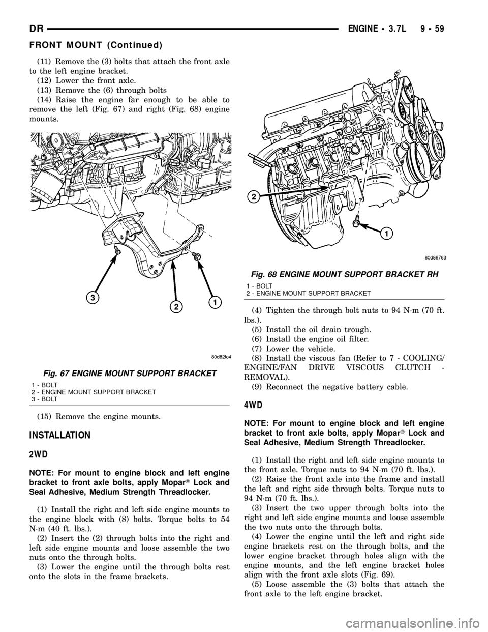
remove the left (Fig. 67) and right (Fig. 68) engine
mounts.
(15) Remove the engine mounts.
INSTALLATION
2WD
NOTE: For mount to engine block and left engine
bracket to front axle bolts, apply MoparTLock and
Seal Adhesive, Medium Strength Threadlocker.
(1) Install the right and left side engine mounts to
the engine block with (8) bolts. Torque bolts to 54
N´m (40 ft. lbs.).
(2) Insert the (2) through bolts into the right and
left side engine mounts and loose assemble the two
nuts onto the through bolts.
(3) Lower the engine until the through bolts rest
onto the slots in the frame brackets.(4) Tighten the through bolt nuts to 94 N´m (70 ft.
lbs.).
(5) Install the oil drain trough.
(6) Install the engine oil filter.
(7) Lower the vehicle.
(8) Install the viscous fan (Refer to 7 - COOLING/
ENGINE/FAN DRIVE VISCOUS CLUTCH -
REMOVAL).
(9) Reconnect the negative battery cable.
4WD
NOTE: For mount to engine block and left engine
bracket to front axle bolts, apply MoparTLock and
Seal Adhesive, Medium Strength Threadlocker.
(1) Install the right and left side engine mounts to
the front axle. Torque nuts to 94 N´m (70 ft. lbs.).
(2) Raise the front axle into the frame and install
the left and right side through bolts. Torque nuts to
94 N´m (70 ft. lbs.).
(3) Insert the two upper through bolts into the
right and left side engine mounts and loose assemble
the two nuts onto the through bolts.
(4) Lower the engine until the left and right side
engine brackets rest on the through bolts, and the
lower engine bracket through holes align with the
engine mounts, and the left engine bracket holes
align with the front axle slots (Fig. 69).
(5) Loose assemble the (3) bolts that attach the
front axle to the left engine bracket.
Fig. 67 ENGINE MOUNT SUPPORT BRACKET
1 - BOLT
2 - ENGINE MOUNT SUPPORT BRACKET
3 - BOLT
Fig. 68 ENGINE MOUNT SUPPORT BRACKET RH
1 - BOLT
2 - ENGINE MOUNT SUPPORT BRACKET
DRENGINE - 3.7L 9 - 59
FRONT MOUNT (Continued)
Page 1283 of 2627

(6) Loose assemble the lower through bolts.
(7) Torque the nuts for the (4) through bolts to 101
N´m (75 ft. lbs.).
(8) Torque the (3) bolts that attach the front axle
to the left engine bracket to 101 N´m (75 ft. lbs.).
(9) Install the oil drain trough.
(10) Install the engine oil filter.(11) Install the front crossmember.
(12) Install the skid plate.
(13) Lower the vehicle.
(14) Install the viscous fan (Refer to 7 - COOL-
ING/ENGINE/FAN DRIVE VISCOUS CLUTCH -
REMOVAL).
(15) Reconnect the negative battery cable.
Fig. 69 ENGINE INSULATOR MOUNTS 4X4
1 - RH INSULATOR TO AXLE BOLT
2 - NUT
3 - PINION SUPPORT MOUNT
4 - LH INSULATOR MOUNT5 - LH INSULATOR TO AXLE BOLT
6 - FRONT AXLE
7 - NUT
8 - RH INSULATOR MOUNT
9 - 60 ENGINE - 3.7LDR
FRONT MOUNT (Continued)
Page 1321 of 2627

Position both the left and right side engine mount
brackets and install the through bolts and nuts.
Tighten nuts to4X2 vehicles95 N´m (70 ft. lbs.).
4X4 vehicles102 N´m (75 ft. lbs.).
(2)4X4 vehiclesInstall locknuts onto the engine
mount brackets. Tighten locknuts to 41 N´m (30 ft.
lbs.).
(3) Remove jack from under the transmission.
(4) Remove Engine Lifting Fixture Special Tool
8347 (Fig. 4).
(5) Remove Special Tools 8400 Lifting Studs.
(6) Position generator wiring behind the oil dip-
stick tube, then install the oil dipstick tube upper
mounting bolt.
(7) Connect both left and right side body ground
straps.
(8) Install power steering pump.
(9) Connect fuel supply line quick connect fitting
(Refer to 14 - FUEL SYSTEM/FUEL DELIVERY/
QUICK CONNECT FITTING - STANDARD PROCE-
DURE).
(10) Connect the vacuum lines at the throttle body
and intake manifold.
(11) Connect engine harness at the following
points (Fig. 3):
²Intake Air Temperature (IAT) Sensor
²Idle Air Control (IAC) Motor
²Fuel Injectors
²Throttle Position (TPS) Switch
²Engine Oil Pressure Switch
²Engine Coolant Temperature (ECT) Sensor
²Manifold Absolute Pressure (MAP) Sensor
²Camshaft Position (CMP) Sensor
²Coil Over Plugs
(12) Position and install heater hoses and tubes
onto intake manifold.
(13) Install the heater hoses onto the heater core
and the engine front cover.
(14) Install generator (Refer to 8 - ELECTRICAL/
CHARGING/GENERATOR - INSTALLATION).
(15) Install A/C condenser (Refer to 24 - HEATING
& AIR CONDITIONING/PLUMBING/A/C CON-
DENSER - INSTALLATION), radiator (Refer to 7 -
COOLING/ENGINE/RADIATOR - INSTALLATION)
and transmission oil cooler.
(16) Connect radiator upper and lower hoses.
(17) Connect the transmission oil cooler lines to
the radiator.
(18) Install accessory drive belt (Refer to 7 -
COOLING/ACCESSORY DRIVE/DRIVE BELTS -INSTALLATION), fan assembly and shroud (Refer to
7 - COOLING/ENGINE/FAN DRIVE VISCOUS
CLUTCH - INSTALLATION).
(19) Install A/C compressor (Refer to 24 - HEAT-
ING & AIR CONDITIONING/PLUMBING/A/C COM-
PRESSOR - INSTALLATION).
(20) Install both breathers. Connect tube to both
crankcase breathers (Fig. 2).
(21) Connect throttle and speed control cables.
(22) Install throttle body resonator assembly and
air inlet hose. Tighten clamps 4 N´m (35 in. lbs.).
(23) Raise vehicle.
(24) Install transmission to engine mounting bolts.
Tighten the bolts to 41 N´m (30 ft. lbs.).
(25) Install torque converter bolts (Automatic
Transmission Only).
(26) Connect crankshaft position sensor (Fig. 1).
(27)4X4 vehiclesPosition and install the axle
isolator bracket onto the axle, transmission and
engine block. Tighten bolts to specification (Refer to 9
- ENGINE - SPECIFICATIONS).
(28) Install starter (Refer to 8 - ELECTRICAL/
STARTING/STARTER MOTOR - INSTALLATION).
CAUTION: The structural cover requires a specific
torque sequence. Failure to follow this sequence
may cause severe damage to the cover.
(29) Install structural cover (Refer to 9 - ENGINE/
ENGINE BLOCK/STRUCTURAL COVER - INSTAL-
LATION).
(30) Install exhaust crossover pipe.
(31) Install engine block heater power cable, If
equipped.
(32)4X4 vehiclesConnect axle vent tube to left
side engine mount.
(33) Lower vehicle.
(34) Check and fill engine oil.
(35) Recharge the A/C system (Refer to 24 - HEAT-
ING & AIR CONDITIONING/PLUMBING/REFRIG-
ERANT - STANDARD PROCEDURE).
(36) Refill the engine cooling system (Refer to 7 -
COOLING - STANDARD PROCEDURE).
(37) Install the battery tray and battery.
(38) Connect the battery positive and negative
cables.
(39) Start the engine and check for leaks.
9 - 98 ENGINE - 4.7LDR
ENGINE - 4.7L (Continued)
Page 1369 of 2627

CAUTION: The structural cover must be held tightly
against both the engine and the transmission bell
housing during tightening sequence. Failure to do
so may cause damage to the cover.
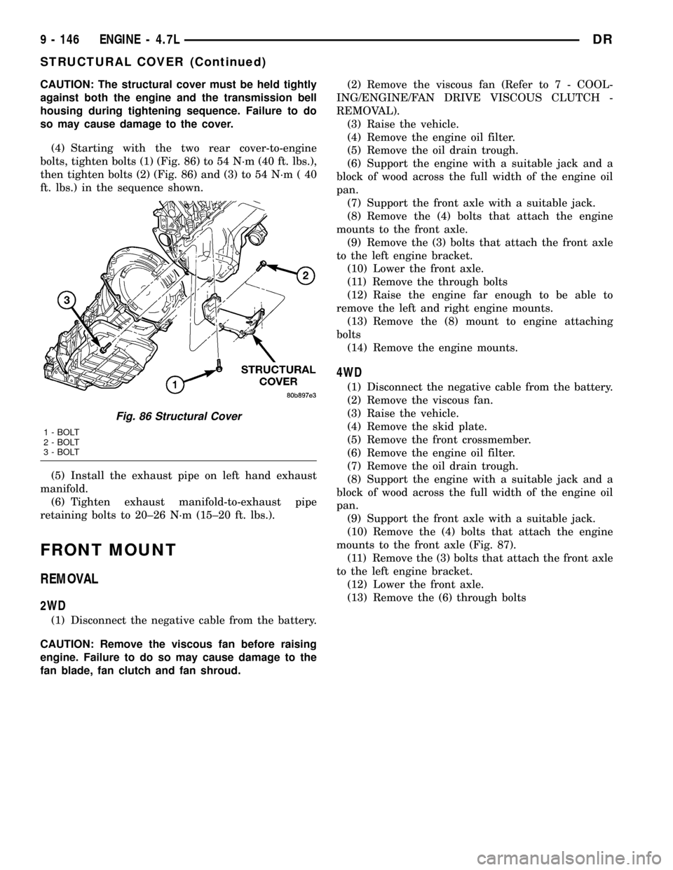
(4) Starting with the two rear cover-to-engine
bolts, tighten bolts (1) (Fig. 86) to 54 N´m (40 ft. lbs.),
then tighten bolts (2) (Fig. 86) and (3) to 54 N´m ( 40
ft. lbs.) in the sequence shown.
(5) Install the exhaust pipe on left hand exhaust
manifold.
(6) Tighten exhaust manifold-to-exhaust pipe
retaining bolts to 20±26 N´m (15±20 ft. lbs.).
FRONT MOUNT
REMOVAL
2WD
(1) Disconnect the negative cable from the battery.
CAUTION: Remove the viscous fan before raising
engine. Failure to do so may cause damage to the
fan blade, fan clutch and fan shroud.(2) Remove the viscous fan (Refer to 7 - COOL-
ING/ENGINE/FAN DRIVE VISCOUS CLUTCH -
REMOVAL).
(3) Raise the vehicle.
(4) Remove the engine oil filter.
(5) Remove the oil drain trough.
(6) Support the engine with a suitable jack and a
block of wood across the full width of the engine oil
pan.
(7) Support the front axle with a suitable jack.
(8) Remove the (4) bolts that attach the engine
mounts to the front axle.
(9) Remove the (3) bolts that attach the front axle
to the left engine bracket.
(10) Lower the front axle.
(11) Remove the through bolts
(12) Raise the engine far enough to be able to
remove the left and right engine mounts.
(13) Remove the (8) mount to engine attaching
bolts
(14) Remove the engine mounts.
4WD
(1) Disconnect the negative cable from the battery.
(2) Remove the viscous fan.
(3) Raise the vehicle.
(4) Remove the skid plate.
(5) Remove the front crossmember.
(6) Remove the engine oil filter.
(7) Remove the oil drain trough.
(8) Support the engine with a suitable jack and a
block of wood across the full width of the engine oil
pan.
(9) Support the front axle with a suitable jack.
(10) Remove the (4) bolts that attach the engine
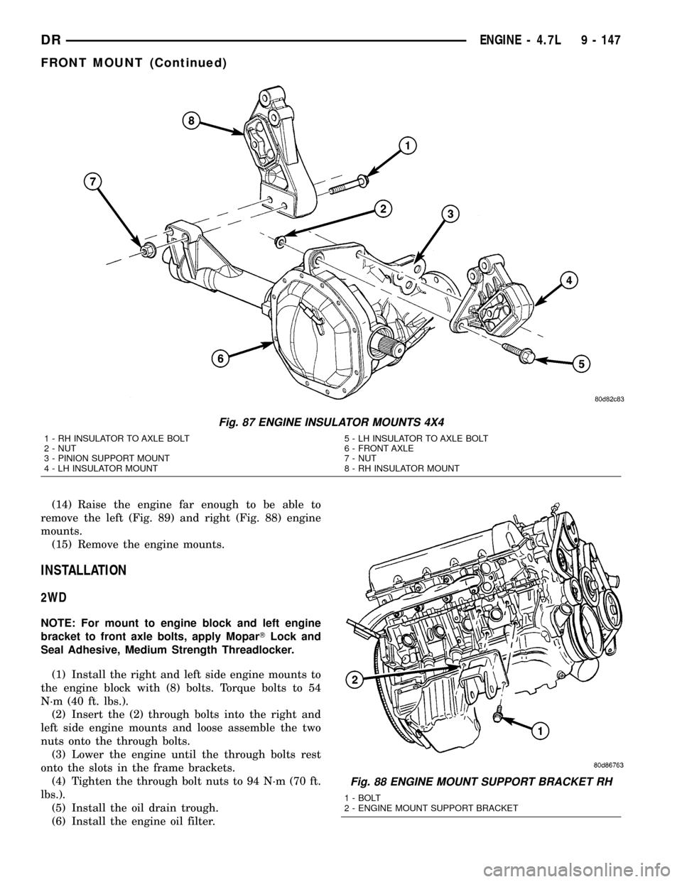
mounts to the front axle (Fig. 87).
(11) Remove the (3) bolts that attach the front axle
to the left engine bracket.
(12) Lower the front axle.
(13) Remove the (6) through bolts
Fig. 86 Structural Cover
1 - BOLT
2 - BOLT
3 - BOLT
9 - 146 ENGINE - 4.7LDR
STRUCTURAL COVER (Continued)
Page 1370 of 2627

(14) Raise the engine far enough to be able to
remove the left (Fig. 89) and right (Fig. 88) engine
mounts.
(15) Remove the engine mounts.
INSTALLATION
2WD
NOTE: For mount to engine block and left engine
bracket to front axle bolts, apply MoparTLock and
Seal Adhesive, Medium Strength Threadlocker.
(1) Install the right and left side engine mounts to
the engine block with (8) bolts. Torque bolts to 54
N´m (40 ft. lbs.).
(2) Insert the (2) through bolts into the right and
left side engine mounts and loose assemble the two
nuts onto the through bolts.
(3) Lower the engine until the through bolts rest
onto the slots in the frame brackets.
(4) Tighten the through bolt nuts to 94 N´m (70 ft.
lbs.).
(5) Install the oil drain trough.
(6) Install the engine oil filter.
Fig. 87 ENGINE INSULATOR MOUNTS 4X4
1 - RH INSULATOR TO AXLE BOLT
2 - NUT
3 - PINION SUPPORT MOUNT
4 - LH INSULATOR MOUNT5 - LH INSULATOR TO AXLE BOLT
6 - FRONT AXLE
7 - NUT
8 - RH INSULATOR MOUNT
Fig. 88 ENGINE MOUNT SUPPORT BRACKET RH
1 - BOLT
2 - ENGINE MOUNT SUPPORT BRACKET
DRENGINE - 4.7L 9 - 147
FRONT MOUNT (Continued)