1998 DODGE RAM 1500 Throttle
[x] Cancel search: ThrottlePage 1843 of 2627

valve moves the overdrive piston into contact with
the overdrive clutch. The direct clutch is disengaged
before the overdrive clutch is engaged. The boost
valve provides increased fluid apply pressure to the
overdrive clutch during 3-4 upshifts, and when accel-
erating in fourth gear. The 3-4 accumulator cushions
overdrive clutch engagement to smooth 3-4 upshifts.
The accumulator is charged at the same time as
apply pressure acts against the overdrive piston.
DIAGNOSIS AND TESTING
DIAGNOSIS AND TESTING - AUTOMATIC
TRANSMISSION
Automatic transmission problems can be a result of
poor engine performance, incorrect fluid level, incor-
rect linkage or cable adjustment, band or hydraulic
control pressure adjustments, hydraulic system mal-
functions or electrical/mechanical component mal-
functions. Begin diagnosis by checking the easily
accessible items such as: fluid level and condition,
linkage adjustments and electrical connections. A
road test will determine if further diagnosis is neces-
sary.
DIAGNOSIS AND TESTING - PRELIMINARY
Two basic procedures are required. One procedure
for vehicles that are drivable and an alternate proce-
dure for disabled vehicles (will not back up or move
forward).
VEHICLE IS DRIVEABLE
(1) Check for transmission fault codes using DRBt
scan tool.
(2) Check fluid level and condition.
(3) Adjust throttle and gearshift linkage if com-
plaint was based on delayed, erratic, or harsh shifts.
(4) Road test and note how transmission upshifts,
downshifts, and engages.
(5) Perform hydraulic pressure test if shift prob-
lems were noted during road test.
(6) Perform air-pressure test to check clutch-band
operation.
VEHICLE IS DISABLED
(1) Check fluid level and condition.
(2) Check for broken or disconnected gearshift or
throttle linkage.
(3) Check for cracked, leaking cooler lines, or loose
or missing pressure-port plugs.
(4) Raise and support vehicle on safety stands,
start engine, shift transmission into gear, and note
following:
(a) If propeller shaft turns but wheels do not,
problem is with differential or axle shafts.
(b) If propeller shaft does not turn and transmis-
sion is noisy, stop engine. Remove oil pan, and
check for debris. If pan is clear, remove transmis-
sion and check for damaged drive plate, converter,
oil pump, or input shaft.
(c) If propeller shaft does not turn and transmis-
sion is not noisy, perform hydraulic-pressure test to
determine if problem is hydraulic or mechanical.
DIAGNOSIS AND TESTING - ROAD TESTING
Before road testing, be sure the fluid level and con-
trol cable adjustments have been checked and
adjusted if necessary. Verify that diagnostic trouble
codes have been resolved.
Observe engine performance during the road test.
A poorly tuned engine will not allow accurate analy-
sis of transmission operation.
Operate the transmission in all gear ranges. Check
for shift variations and engine flare which indicates
slippage. Note if shifts are harsh, spongy, delayed,
early, or if part throttle downshifts are sensitive.
Slippage indicated by engine flare, usually means
clutch, band or overrunning clutch problems. If the
condition is advanced, an overhaul will be necessary
to restore normal operation.
A slipping clutch or band can often be determined
by comparing which internal units are applied in the
various gear ranges. The Clutch and Band Applica-
tion chart provides a basis for analyzing road test
results.
21 - 140 AUTOMATIC TRANSMISSION - 48REDR
AUTOMATIC TRANSMISSION - 48RE (Continued)
Page 1845 of 2627

The rear servo and governor pressure ports are at
the right rear of the transmission case. The overdrive
clutch pressure port is at the left rear of the case.
Test One - Transmission In Manual Low
This test checks pump output, pressure regulation,
and condition of the rear clutch and servo circuit.
Both test gauges are required for this test.
(1) Connect tachometer to engine. Position tachom-
eter so it can be observed from driver seat if helper
will be operating engine. Raise vehicle on hoist that
will allow rear wheels to rotate freely.
(2) Connect 100 psi Gauge C-3292 to accumulator
port. Then connect 300 psi Gauge C-3293-SP to rear
servo port.
(3) Disconnect throttle and gearshift cables from
levers on transmission valve body manual shaft.
(4) Have helper start and run engine at 1000 rpm.
(5) Move transmission shift lever fully forward
into 1 range.
(6) Gradually move transmission throttle lever
from full forward to full rearward position and note
pressures on both gauges:²Line pressure at accumulator port should be
54-60 psi (372-414 kPa) with throttle lever forward
and gradually increase to 90-96 psi (621-662 kPa) as
throttle lever is moved rearward.
²Rear servo pressure should be same as line pres-
sure within 3 psi (20.68 kPa).
Test Two - Transmission In 2 Range
This test checks pump output, line pressure and
pressure regulation. Use 100 psi Test Gauge C-3292
for this test.
(1) Leave vehicle in place on hoist and leave Test
Gauge C-3292 connected to accumulator port.
(2) Have helper start and run engine at 1000 rpm.
(3) Move transmission shift lever one detent rear-
ward from full forward position. This is 2 range.
(4) Move transmission throttle lever from full for-
ward to full rearward position and read pressure on
gauge.
(5) Line pressure should be 54-60 psi (372-414
kPa) with throttle lever forward and gradually
increase to 90-96 psi (621-662 kPa) as lever is moved
rearward.
Test Three - Transmission In D Range Third Gear
This test checks pressure regulation and condition
of the clutch circuits. Both test gauges are required
for this test.
(1) Turn OD switch off.
(2) Leave vehicle on hoist and leave Gauge C-3292
in place at accumulator port.
(3) Move Gauge C-3293-SP over to front servo port
for this test.
(4) Have helper start and run engine at 1600 rpm
for this test.
(5) Move transmission shift lever two detents rear-
ward from full forward position. This is D range.
(6) Read pressures on both gauges as transmission
throttle lever is gradually moved from full forward to
full rearward position:
²Line pressure at accumulator in D range third
gear, should be 54-60 psi (372-414 kPa) with throttle
lever forward and increase as lever is moved rear-
ward.
²Front servo pressure in D range third gear,
should be within 3 psi (21 kPa) of line pressure up to
kickdown point.
Test Four - Transmission In Reverse
This test checks pump output, pressure regulation
and the front clutch and rear servo circuits. Use 300
psi Test Gauge C-3293-SP for this test.
(1) Leave vehicle on hoist and leave gauge C-3292
in place at accumulator port.
(2) Move 300 psi Gauge C-3293-SP back to rear
servo port.
Fig. 9 Pressure Test Port Locations
1 - REAR SERVO TEST PORT
2 - GOVERNOR TEST PORT
3 - ACCUMULATOR TEST PORT
4 - FRONT SERVO TEST PORT
5 - OVERDRIVE CLUTCH TEST PORT
21 - 142 AUTOMATIC TRANSMISSION - 48REDR
AUTOMATIC TRANSMISSION - 48RE (Continued)
Page 1846 of 2627
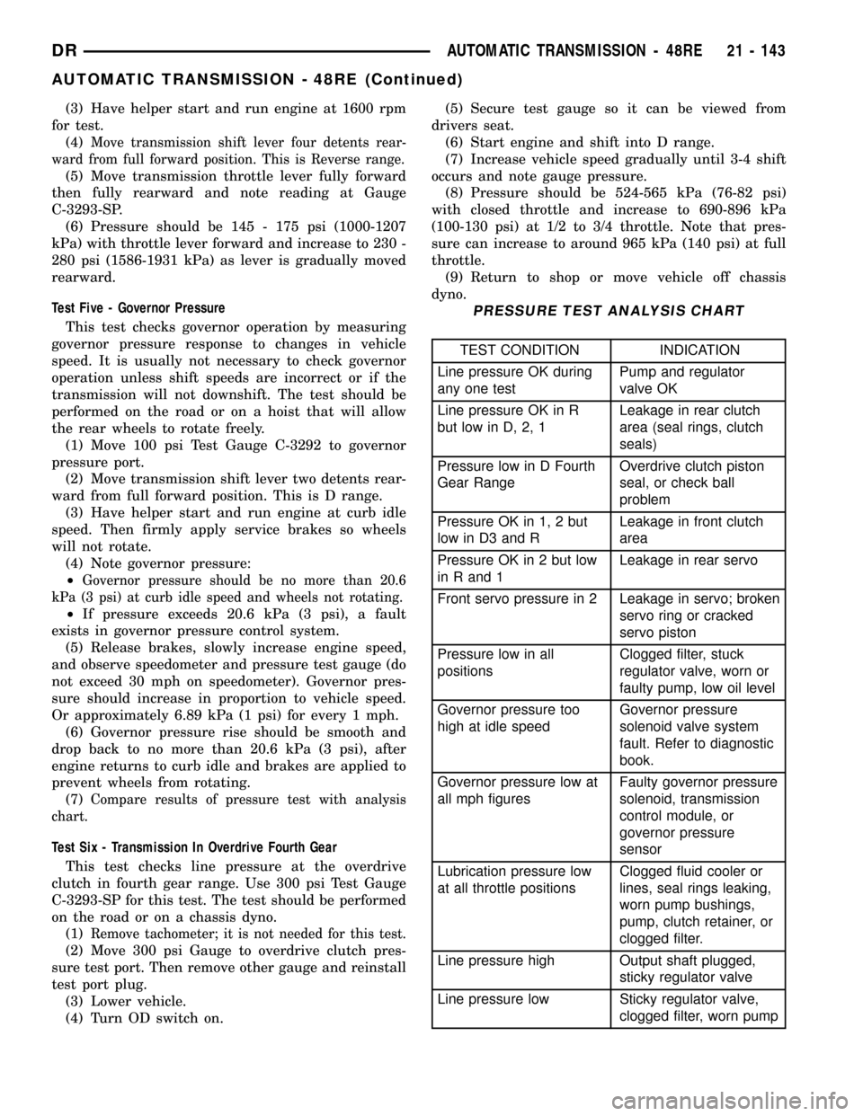
(3) Have helper start and run engine at 1600 rpm
for test.
(4)
Move transmission shift lever four detents rear-
ward from full forward position. This is Reverse range.
(5) Move transmission throttle lever fully forward
then fully rearward and note reading at Gauge
C-3293-SP.
(6) Pressure should be 145 - 175 psi (1000-1207
kPa) with throttle lever forward and increase to 230 -
280 psi (1586-1931 kPa) as lever is gradually moved
rearward.
Test Five - Governor Pressure
This test checks governor operation by measuring
governor pressure response to changes in vehicle
speed. It is usually not necessary to check governor
operation unless shift speeds are incorrect or if the
transmission will not downshift. The test should be
performed on the road or on a hoist that will allow
the rear wheels to rotate freely.
(1) Move 100 psi Test Gauge C-3292 to governor
pressure port.
(2) Move transmission shift lever two detents rear-
ward from full forward position. This is D range.
(3) Have helper start and run engine at curb idle
speed. Then firmly apply service brakes so wheels
will not rotate.
(4) Note governor pressure:
²
Governor pressure should be no more than 20.6
kPa (3 psi) at curb idle speed and wheels not rotating.
²If pressure exceeds 20.6 kPa (3 psi), a fault
exists in governor pressure control system.
(5) Release brakes, slowly increase engine speed,
and observe speedometer and pressure test gauge (do
not exceed 30 mph on speedometer). Governor pres-
sure should increase in proportion to vehicle speed.
Or approximately 6.89 kPa (1 psi) for every 1 mph.
(6) Governor pressure rise should be smooth and
drop back to no more than 20.6 kPa (3 psi), after
engine returns to curb idle and brakes are applied to
prevent wheels from rotating.
(7)
Compare results of pressure test with analysis
chart.
Test Six - Transmission In Overdrive Fourth Gear
This test checks line pressure at the overdrive
clutch in fourth gear range. Use 300 psi Test Gauge
C-3293-SP for this test. The test should be performed
on the road or on a chassis dyno.
(1)
Remove tachometer; it is not needed for this test.
(2) Move 300 psi Gauge to overdrive clutch pres-
sure test port. Then remove other gauge and reinstall
test port plug.
(3) Lower vehicle.
(4) Turn OD switch on.(5) Secure test gauge so it can be viewed from
drivers seat.
(6) Start engine and shift into D range.
(7) Increase vehicle speed gradually until 3-4 shift
occurs and note gauge pressure.
(8) Pressure should be 524-565 kPa (76-82 psi)
with closed throttle and increase to 690-896 kPa
(100-130 psi) at 1/2 to 3/4 throttle. Note that pres-
sure can increase to around 965 kPa (140 psi) at full
throttle.
(9) Return to shop or move vehicle off chassis
dyno.
PRESSURE TEST ANALYSIS CHART
TEST CONDITION INDICATION
Line pressure OK during
any one testPump and regulator
valve OK
Line pressure OK in R
but low in D, 2, 1Leakage in rear clutch
area (seal rings, clutch
seals)
Pressure low in D Fourth
Gear RangeOverdrive clutch piston
seal, or check ball
problem
Pressure OK in 1, 2 but
low in D3 and RLeakage in front clutch
area
Pressure OK in 2 but low
in R and 1Leakage in rear servo
Front servo pressure in 2 Leakage in servo; broken
servo ring or cracked
servo piston
Pressure low in all
positionsClogged filter, stuck
regulator valve, worn or
faulty pump, low oil level
Governor pressure too
high at idle speedGovernor pressure
solenoid valve system
fault. Refer to diagnostic
book.
Governor pressure low at
all mph figuresFaulty governor pressure
solenoid, transmission
control module, or
governor pressure
sensor
Lubrication pressure low
at all throttle positionsClogged fluid cooler or
lines, seal rings leaking,
worn pump bushings,
pump, clutch retainer, or
clogged filter.
Line pressure high Output shaft plugged,
sticky regulator valve
Line pressure low Sticky regulator valve,
clogged filter, worn pump
DRAUTOMATIC TRANSMISSION - 48RE 21 - 143
AUTOMATIC TRANSMISSION - 48RE (Continued)
Page 1849 of 2627
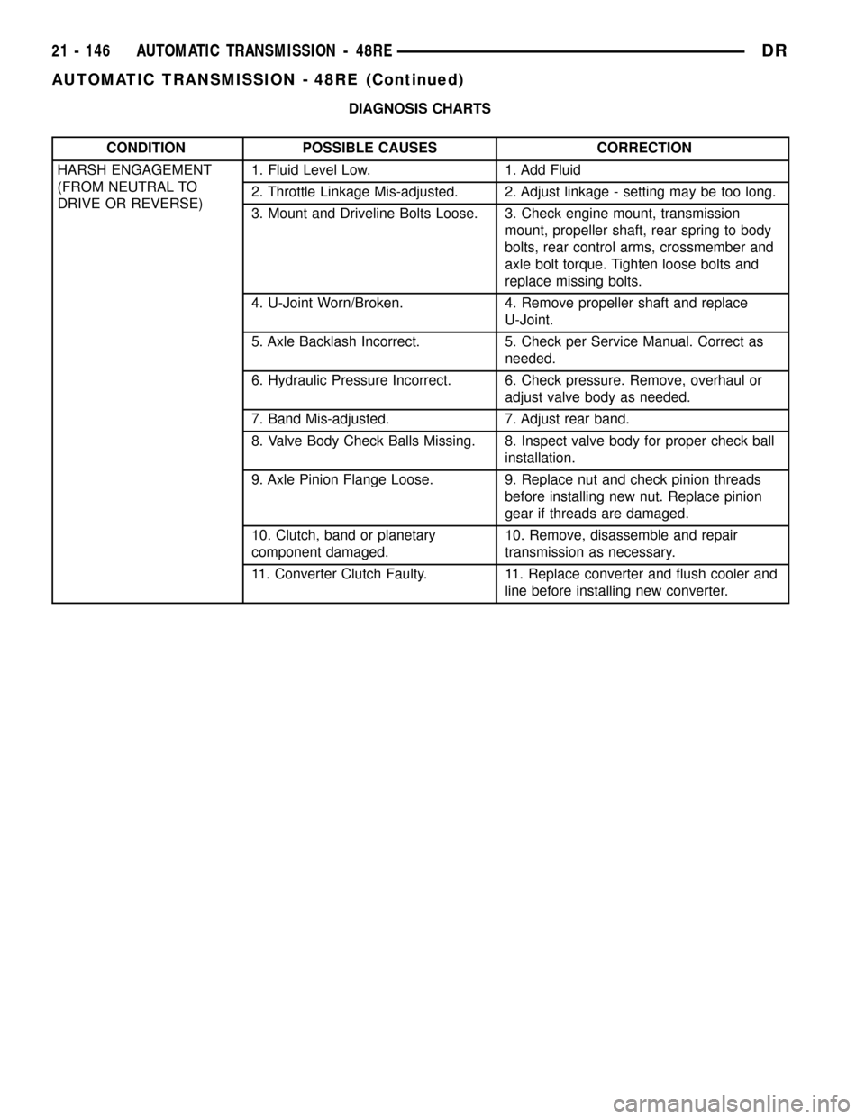
DIAGNOSIS CHARTS
CONDITION POSSIBLE CAUSES CORRECTION
HARSH ENGAGEMENT
(FROM NEUTRAL TO
DRIVE OR REVERSE)1. Fluid Level Low. 1. Add Fluid
2. Throttle Linkage Mis-adjusted. 2. Adjust linkage - setting may be too long.
3. Mount and Driveline Bolts Loose. 3. Check engine mount, transmission
mount, propeller shaft, rear spring to body
bolts, rear control arms, crossmember and
axle bolt torque. Tighten loose bolts and
replace missing bolts.
4. U-Joint Worn/Broken. 4. Remove propeller shaft and replace
U-Joint.
5. Axle Backlash Incorrect. 5. Check per Service Manual. Correct as
needed.
6. Hydraulic Pressure Incorrect. 6. Check pressure. Remove, overhaul or
adjust valve body as needed.
7. Band Mis-adjusted. 7. Adjust rear band.
8. Valve Body Check Balls Missing. 8. Inspect valve body for proper check ball
installation.
9. Axle Pinion Flange Loose. 9. Replace nut and check pinion threads
before installing new nut. Replace pinion
gear if threads are damaged.
10. Clutch, band or planetary
component damaged.10. Remove, disassemble and repair
transmission as necessary.
11. Converter Clutch Faulty. 11. Replace converter and flush cooler and
line before installing new converter.
21 - 146 AUTOMATIC TRANSMISSION - 48REDR
AUTOMATIC TRANSMISSION - 48RE (Continued)
Page 1851 of 2627
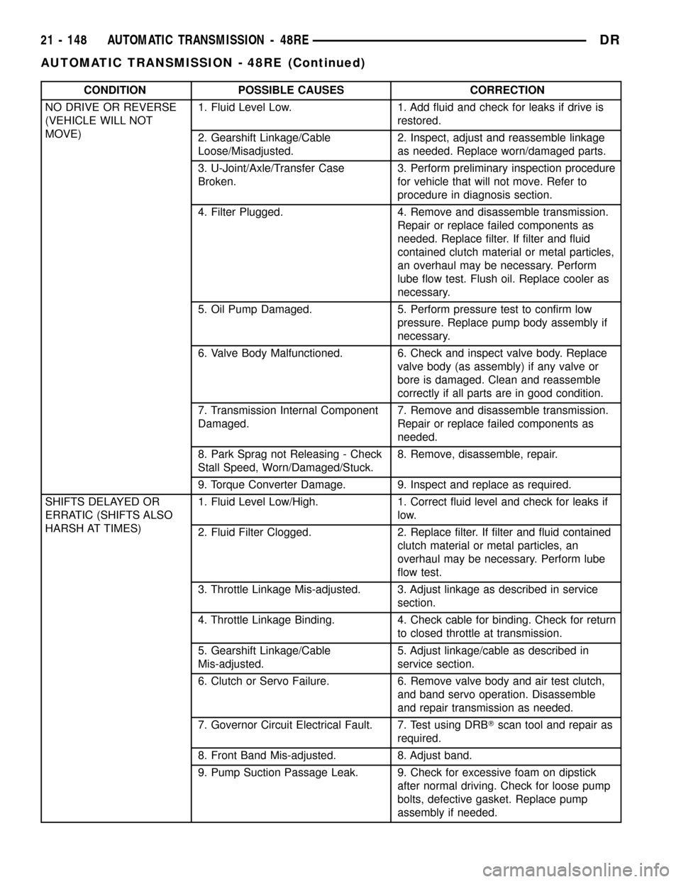
CONDITION POSSIBLE CAUSES CORRECTION
NO DRIVE OR REVERSE
(VEHICLE WILL NOT
MOVE)1. Fluid Level Low. 1. Add fluid and check for leaks if drive is
restored.
2. Gearshift Linkage/Cable
Loose/Misadjusted.2. Inspect, adjust and reassemble linkage
as needed. Replace worn/damaged parts.
3. U-Joint/Axle/Transfer Case
Broken.3. Perform preliminary inspection procedure
for vehicle that will not move. Refer to
procedure in diagnosis section.
4. Filter Plugged. 4. Remove and disassemble transmission.
Repair or replace failed components as
needed. Replace filter. If filter and fluid
contained clutch material or metal particles,
an overhaul may be necessary. Perform
lube flow test. Flush oil. Replace cooler as
necessary.
5. Oil Pump Damaged. 5. Perform pressure test to confirm low
pressure. Replace pump body assembly if
necessary.
6. Valve Body Malfunctioned. 6. Check and inspect valve body. Replace
valve body (as assembly) if any valve or
bore is damaged. Clean and reassemble
correctly if all parts are in good condition.
7. Transmission Internal Component
Damaged.7. Remove and disassemble transmission.
Repair or replace failed components as
needed.
8. Park Sprag not Releasing - Check
Stall Speed, Worn/Damaged/Stuck.8. Remove, disassemble, repair.
9. Torque Converter Damage. 9. Inspect and replace as required.
SHIFTS DELAYED OR
ERRATIC (SHIFTS ALSO
HARSH AT TIMES)1. Fluid Level Low/High. 1. Correct fluid level and check for leaks if
low.
2. Fluid Filter Clogged. 2. Replace filter. If filter and fluid contained
clutch material or metal particles, an
overhaul may be necessary. Perform lube
flow test.
3. Throttle Linkage Mis-adjusted. 3. Adjust linkage as described in service
section.
4. Throttle Linkage Binding. 4. Check cable for binding. Check for return
to closed throttle at transmission.
5. Gearshift Linkage/Cable
Mis-adjusted.5. Adjust linkage/cable as described in
service section.
6. Clutch or Servo Failure. 6. Remove valve body and air test clutch,
and band servo operation. Disassemble
and repair transmission as needed.
7. Governor Circuit Electrical Fault. 7. Test using DRBTscan tool and repair as
required.
8. Front Band Mis-adjusted. 8. Adjust band.
9. Pump Suction Passage Leak. 9. Check for excessive foam on dipstick
after normal driving. Check for loose pump
bolts, defective gasket. Replace pump
assembly if needed.
21 - 148 AUTOMATIC TRANSMISSION - 48REDR
AUTOMATIC TRANSMISSION - 48RE (Continued)
Page 1853 of 2627
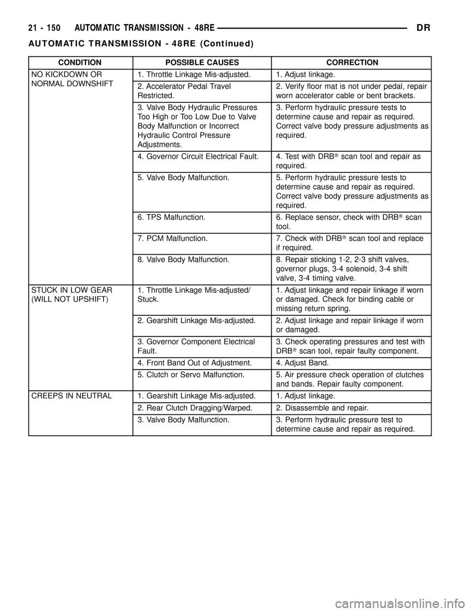
CONDITION POSSIBLE CAUSES CORRECTION
NO KICKDOWN OR
NORMAL DOWNSHIFT1. Throttle Linkage Mis-adjusted. 1. Adjust linkage.
2. Accelerator Pedal Travel
Restricted.2. Verify floor mat is not under pedal, repair
worn accelerator cable or bent brackets.
3. Valve Body Hydraulic Pressures
Too High or Too Low Due to Valve
Body Malfunction or Incorrect
Hydraulic Control Pressure
Adjustments.3. Perform hydraulic pressure tests to
determine cause and repair as required.
Correct valve body pressure adjustments as
required.
4. Governor Circuit Electrical Fault. 4. Test with DRBTscan tool and repair as
required.
5. Valve Body Malfunction. 5. Perform hydraulic pressure tests to
determine cause and repair as required.
Correct valve body pressure adjustments as
required.
6. TPS Malfunction. 6. Replace sensor, check with DRBTscan
tool.
7. PCM Malfunction. 7. Check with DRBTscan tool and replace
if required.
8. Valve Body Malfunction. 8. Repair sticking 1-2, 2-3 shift valves,
governor plugs, 3-4 solenoid, 3-4 shift
valve, 3-4 timing valve.
STUCK IN LOW GEAR
(WILL NOT UPSHIFT)1. Throttle Linkage Mis-adjusted/
Stuck.1. Adjust linkage and repair linkage if worn
or damaged. Check for binding cable or
missing return spring.
2. Gearshift Linkage Mis-adjusted. 2. Adjust linkage and repair linkage if worn
or damaged.
3. Governor Component Electrical
Fault.3. Check operating pressures and test with
DRBTscan tool, repair faulty component.
4. Front Band Out of Adjustment. 4. Adjust Band.
5. Clutch or Servo Malfunction. 5. Air pressure check operation of clutches
and bands. Repair faulty component.
CREEPS IN NEUTRAL 1. Gearshift Linkage Mis-adjusted. 1. Adjust linkage.
2. Rear Clutch Dragging/Warped. 2. Disassemble and repair.
3. Valve Body Malfunction. 3. Perform hydraulic pressure test to
determine cause and repair as required.
21 - 150 AUTOMATIC TRANSMISSION - 48REDR
AUTOMATIC TRANSMISSION - 48RE (Continued)
Page 1854 of 2627
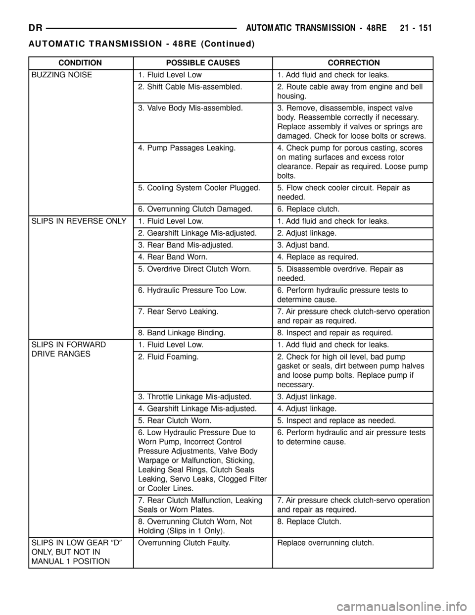
CONDITION POSSIBLE CAUSES CORRECTION
BUZZING NOISE 1. Fluid Level Low 1. Add fluid and check for leaks.
2. Shift Cable Mis-assembled. 2. Route cable away from engine and bell
housing.
3. Valve Body Mis-assembled. 3. Remove, disassemble, inspect valve
body. Reassemble correctly if necessary.
Replace assembly if valves or springs are
damaged. Check for loose bolts or screws.
4. Pump Passages Leaking. 4. Check pump for porous casting, scores
on mating surfaces and excess rotor
clearance. Repair as required. Loose pump
bolts.
5. Cooling System Cooler Plugged. 5. Flow check cooler circuit. Repair as
needed.
6. Overrunning Clutch Damaged. 6. Replace clutch.
SLIPS IN REVERSE ONLY 1. Fluid Level Low. 1. Add fluid and check for leaks.
2. Gearshift Linkage Mis-adjusted. 2. Adjust linkage.
3. Rear Band Mis-adjusted. 3. Adjust band.
4. Rear Band Worn. 4. Replace as required.
5. Overdrive Direct Clutch Worn. 5. Disassemble overdrive. Repair as
needed.
6. Hydraulic Pressure Too Low. 6. Perform hydraulic pressure tests to
determine cause.
7. Rear Servo Leaking. 7. Air pressure check clutch-servo operation
and repair as required.
8. Band Linkage Binding. 8. Inspect and repair as required.
SLIPS IN FORWARD
DRIVE RANGES1. Fluid Level Low. 1. Add fluid and check for leaks.
2. Fluid Foaming. 2. Check for high oil level, bad pump
gasket or seals, dirt between pump halves
and loose pump bolts. Replace pump if
necessary.
3. Throttle Linkage Mis-adjusted. 3. Adjust linkage.
4. Gearshift Linkage Mis-adjusted. 4. Adjust linkage.
5. Rear Clutch Worn. 5. Inspect and replace as needed.
6. Low Hydraulic Pressure Due to
Worn Pump, Incorrect Control
Pressure Adjustments, Valve Body
Warpage or Malfunction, Sticking,
Leaking Seal Rings, Clutch Seals
Leaking, Servo Leaks, Clogged Filter
or Cooler Lines.6. Perform hydraulic and air pressure tests
to determine cause.
7. Rear Clutch Malfunction, Leaking
Seals or Worn Plates.7. Air pressure check clutch-servo operation
and repair as required.
8. Overrunning Clutch Worn, Not
Holding (Slips in 1 Only).8. Replace Clutch.
SLIPS IN LOW GEAR9D9
ONLY, BUT NOT IN
MANUAL 1 POSITIONOverrunning Clutch Faulty. Replace overrunning clutch.
DRAUTOMATIC TRANSMISSION - 48RE 21 - 151
AUTOMATIC TRANSMISSION - 48RE (Continued)
Page 1856 of 2627
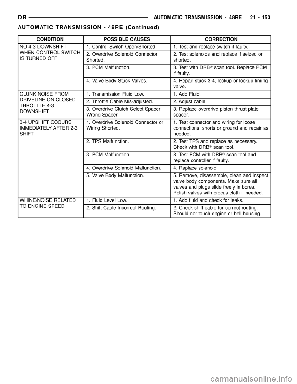
CONDITION POSSIBLE CAUSES CORRECTION
NO 4-3 DOWNSHIFT
WHEN CONTROL SWITCH
IS TURNED OFF1. Control Switch Open/Shorted. 1. Test and replace switch if faulty.
2. Overdrive Solenoid Connector
Shorted.2. Test solenoids and replace if seized or
shorted.
3. PCM Malfunction. 3. Test with DRBTscan tool. Replace PCM
if faulty.
4. Valve Body Stuck Valves. 4. Repair stuck 3-4, lockup or lockup timing
valve.
CLUNK NOISE FROM
DRIVELINE ON CLOSED
THROTTLE 4-3
DOWNSHIFT1. Transmission Fluid Low. 1. Add Fluid.
2. Throttle Cable Mis-adjusted. 2. Adjust cable.
3. Overdrive Clutch Select Spacer
Wrong Spacer.3. Replace overdrive piston thrust plate
spacer.
3-4 UPSHIFT OCCURS
IMMEDIATELY AFTER 2-3
SHIFT1. Overdrive Solenoid Connector or
Wiring Shorted.1. Test connector and wiring for loose
connections, shorts or ground and repair as
needed.
2. TPS Malfunction. 2. Test TPS and replace as necessary.
Check with DRBTscan tool.
3. PCM Malfunction. 3. Test PCM with DRBTscan tool and
replace controller if faulty.
4. Overdrive Solenoid Malfunction. 4. Replace solenoid.
5. Valve Body Malfunction. 5. Remove, disassemble, clean and inspect
valve body components. Make sure all
valves and plugs slide freely in bores.
Polish valves with crocus cloth if needed.
WHINE/NOISE RELATED
TO ENGINE SPEED1. Fluid Level Low. 1. Add fluid and check for leaks.
2. Shift Cable Incorrect Routing. 2. Check shift cable for correct routing.
Should not touch engine or bell housing.
DRAUTOMATIC TRANSMISSION - 48RE 21 - 153
AUTOMATIC TRANSMISSION - 48RE (Continued)