1998 DODGE RAM 1500 Power steering
[x] Cancel search: Power steeringPage 1659 of 2627

DIAGNOSIS AND TESTING - POWER STEERING
FLOW AND PRESSURE
The following procedure is used to test the opera-
tion of the power steering system on the vehicle. This
test will provide the gallons per minute (GPM) or
flow rate of the power steering pump along with the
maximum relief pressure. Perform test any time a
power steering system problem is present. This test
will determine if the power steering pump or power
steering gear is not functioning properly. The follow-
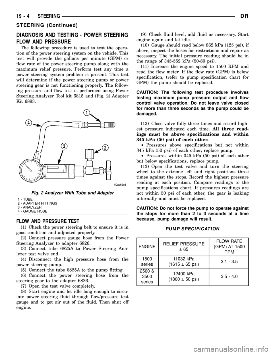
ing pressure and flow test is performed using Power
Steering Analyzer Tool kit 6815 and (Fig. 2) Adapter
Kit 6893.
FLOW AND PRESSURE TEST
(1) Check the power steering belt to ensure it is in
good condition and adjusted properly.
(2) Connect pressure gauge hose from the Power
Steering Analyzer to adapter 6826.
(3) Connect tube 6825A to Power Steering Ana-
lyzer test valve end.
(4) Disconnect the high pressure hose from the
power steering pump.
(5) Connect the tube 6825A to the pump fitting.
(6) Connect the power steering hose from the
steering gear to the adapter 6826.
(7) Open the test valve completely.
(8) Start engine and let idle long enough to circu-
late power steering fluid through flow/pressure test
gauge and to get air out of the fluid. Then shut off
engine.(9) Check fluid level, add fluid as necessary. Start
engine again and let idle.
(10) Gauge should read below 862 kPa (125 psi), if
above, inspect the hoses for restrictions and repair as
necessary. The initial pressure reading should be in
the range of 345-552 kPa (50-80 psi).
(11) Increase the engine speed to 1500 RPM and
read the flow meter. If the flow rate (GPM) is below
specification, (refer to pump specification chart for
GPM) the pump should be replaced.
CAUTION: The following test procedure involves
testing maximum pump pressure output and flow
control valve operation. Do not leave valve closed
for more than three seconds as the pump could be
damaged.
(12) Close valve fully three times and record high-
est pressure indicated each time.All three read-
ings must be above specifications and within
345 kPa (50 psi) of each other.
²Pressures above specifications but not within
345 kPa (50 psi) of each other, replace pump.
²Pressures within 345 kPa (50 psi) of each other
but below specifications, replace pump.
(13) Open the test valve and turn the steering
wheel to the extreme left and right positions three
times against the stops. Record the highest pressure
reading at each position. Compare readings to the
pump specifications chart. If pressures readings are
not within 50 psi of each other, the gear is leaking
internally and must be replaced.
CAUTION: Do not force the pump to operate against
the stops for more than 2 to 3 seconds at a time
because, pump damage will result.PUMP SPECIFICATION
ENGINERELIEF PRESSURE
65FLOW RATE
(GPM) AT 1500
RPM
1500
series11032 kPa
(1615 65 psi)3.1 - 3.5
2500 &
3500
series12400 kPa
(1800 50 psi)3.5 - 4.0
Fig. 2 Analyzer With Tube and Adapter
1 - TUBE
2 - ADAPTER FITTINGS
3 - ANALYZER
4 - GAUGE HOSE
19 - 4 STEERINGDR
STEERING (Continued)
Page 1660 of 2627

SPECIAL TOOLS
STEERING
PULLER - 8677
ADAPTERS, POWER STEERING FLOW/PRESSURE
TESTER - 6893
ANALYZER SET, POWER STEERING FLOW/
PRESSURE 6815
ADAPTER, POWER STEERING FLOW/PRESSURE -
6825A
DRSTEERING 19 - 5
STEERING (Continued)
Page 1672 of 2627

GEAR - INDEPENDENT FRONT SUSPENSION
TABLE OF CONTENTS
page page
GEAR - INDEPENDENT FRONT SUSPENSION
DESCRIPTION.........................17
REMOVAL.............................17
INSTALLATION.........................18
SPECIFICATIONS
TORQUE CHART......................19BUSHING
REMOVAL.............................19
INSTALLATION.........................19
GEAR - INDEPENDENT FRONT
SUSPENSION
DESCRIPTION
A rack and pinion steering gears (Fig. 1) is made
up of two main components, the pinon shaft and the
rack. The gear cannot be adjusted or internally ser-
viced. If a malfunction or a fluid leak occurs, the gear
must be replaced as an assembly.
REMOVAL
NOTE: The steering column on vehicles with an
automatic transmission may not be equipped with
an internal locking shaft that allows the ignition key
cylinder to be locked with the key. Alternative meth-
ods of locking the steering wheel for service will
have to be used.
(1) Lock the steering wheel.(2) Drain and siphon the power steering fluid from
the reservoir.
(3) Raise the vehicle.
(4) Remove and discard the steering coupler pinch
bolt.
(5) Remove the power steering hoses from the rack
& pinion.
(6) Remove the tire and wheel assembly.
(7) Remove the tie rod end nuts and separate tie
rod ends from the knuckles with Special tool 8677
(Refer to 19 - STEERING/LINKAGE/TIE ROD END -
REMOVAL).
(8) Remove the skid plate (Refer to 13 - FRAME &
BUMPERS/FRAME/FRONT SKID PLATE -
REMOVAL).
(9) Remove the rack & pinion mounting bolts. (Fig.
2) & (Fig. 3)
(10) Remove the rack & pinion from the vehicle.
Fig. 1 STEERING GEAR
1 - OUTER TIE ROD ENDS
2 - MOUNTING BUSHINGS
3 - BELLOWS
Fig. 2 STEERING GEAR MOUNTING BOLTS
1 - STEERING GEAR MOUNTING BOLTS 4X4
DRGEAR - INDEPENDENT FRONT SUSPENSION 19 - 17
Page 1673 of 2627

INSTALLATION
NOTE: Before installing gear inspect bushings and
replace if worn or damaged.
NOTE: In the frame there is two holes for the
mounting of the steering gear one is slotted and
one is round, When tightening the gear to specifi-
cations make sure to tighten the mounting bolt with
the hole first to avoided movement of the steering
gear.
(1) Install the gear on the front crossmember and
tighten the mounting bolts to 319 N´m (235 ft. lbs.).
(Fig. 4) & (Fig. 3).
(2) Slide the shaft coupler onto the gear. Install
newpinch bolt and tighten to 49 N´m (36 ft. lbs.).
(3) Clean and dry the tie rod end studs and the
knuckle tapers.
(4) Install the tie rod ends into the steering knuck-
les and tighten the nuts to 61 N´m (45 ft. lbs.) thenan additional 90É. (Refer to 19 - STEERING/LINK-
AGE/TIE ROD END - INSTALLATION).
(5) Install the pressure power steering hose to the
steering gear and tighten to 32 N´m (23 ft. lbs.).
(Refer to 19 - STEERING/PUMP/HOSES - INSTAL-
LATION).
(6) Install the return power steering hose to the
steering gear and tighten to 71 N´m (52 ft. lbs.).
(Refer to 19 - STEERING/PUMP/HOSES - INSTAL-
LATION).
(7) Install the front skid plate (Refer to 13 -
FRAME & BUMPERS/FRAME/FRONT SKID PLATE
- INSTALLATION).
(8) Install the tire and wheel assembly (Refer to 22
- TIRES/WHEELS/WHEELS - STANDARD PROCE-
DURE).
(9) Remove the support and lower the vehicle.
(10) Fill the system with fluid, (Refer to 19 -
STEERING/PUMP - STANDARD PROCEDURE).
(11) Adjust the toe position. (Refer to 2 - SUSPEN-
SION/WHEEL ALIGNMENT - STANDARD PROCE-
DURE).
Fig. 3 STEERING GEAR 4X2
1-SWAYBAR
2 - STEERING GEAR
3 - LEFT OUTER TIE ROD END
4 - LOWER CONTROL ARMS
5 - LEFT INNER & RIGHT OUTER (TIE ROD ENDS)
Fig. 4 STEERING GEAR 4X4
1 - FRONT AXLE
2 - STEERING GEAR MOUNTING NUTS & BUSHINGS
19 - 18 GEAR - INDEPENDENT FRONT SUSPENSIONDR
GEAR - INDEPENDENT FRONT SUSPENSION (Continued)
Page 1674 of 2627

SPECIFICATIONS
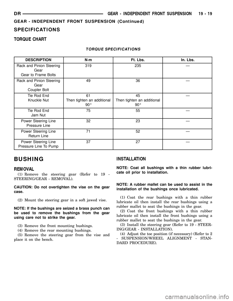
TORQUE CHART
TORQUE SPECIFICATIONS
DESCRIPTION N´m Ft. Lbs. In. Lbs.
Rack and Pinion Steering
Gear
Gear to Frame Bolts319 235 Ð
Rack and Pinion Steering
Gear
Coupler Bolt49 36 Ð
Tie Rod End
Knuckle Nut61
Then tighten an additional
90É45
Then tighten an additional
90ÉÐ
Tie Rod End
Jam Nut75 55 Ð
Power Steering Line
Pressure Line32 23 Ð
Power Steering Line
Return Line71 52 Ð
Power Steering Line
Pressure Line To Pump37 27 Ð
BUSHING
REMOVAL
(1) Remove the steering gear (Refer to 19 -
STEERING/GEAR - REMOVAL).
CAUTION: Do not overtighten the vise on the gear
case.
(2) Mount the steering gear in a soft jawed vise.
NOTE: If the bushings are seized a brass punch can
be used to remove the bushings from the gear
using care not to strike the gear.
(3) Remove the front mounting bushings.
(4) Remove the rear mounting bushings.
(5) Remove the steering gear from the vise and
place it on the bench.
INSTALLATION
NOTE: Coat all bushings with a thin rubber lubri-
cate oil prior to installation.
NOTE: A rubber mallet can be used to assist in the
installation of the bushings once lubricated.
(1) Coat the rear bushings with a thin rubber
lubricate oil then install the rear bushings using a
rubber mallet to seat the bushings in the gear.
(2) Coat the front bushings with a thin rubber
lubricate oil then install the front bushings using a
rubber mallet to seat the bushings in the gear.
(3) Install the steering gear (Refer to 19 - STEER-
ING/GEAR - INSTALLATION).
(4) Adjust the toe position (if necessary) (Refer to 2
- SUSPENSION/WHEEL ALIGNMENT - STAN-
DARD PROCEDURE).
DRGEAR - INDEPENDENT FRONT SUSPENSION 19 - 19
GEAR - INDEPENDENT FRONT SUSPENSION (Continued)
Page 1675 of 2627

GEAR - LINK/COIL
TABLE OF CONTENTS
page page
GEAR - LINK/COIL
DESCRIPTION.........................20
OPERATION...........................20
REMOVAL.............................20
INSTALLATION.........................21
ADJUSTMENTS
ADJUSTMENT........................21
SPECIFICATIONS
POWER STEERING GEAR..............22
TORQUE CHART......................23
SPECIAL TOOLS
POWER STEERING GEAR..............23
PITMAN SHAFT SEAL
REMOVAL
REMOVAL - GAS ENGINE...............25REMOVAL - DIESEL...................25
INSTALLATION
INSTALLATION - GAS ENGINE...........26
INSTALLATION - DIESEL................26
STEERING GEAR INPUT SHAFT SEAL
REMOVAL.............................27
INSTALLATION.........................29
PITMAN SHAFT
REMOVAL
REMOVAL - GAS......................30
REMOVAL - DIESEL...................30
INSTALLATION
INSTALLATION - GAS..................31
INSTALLATION - DIESEL................31
GEAR - LINK/COIL
DESCRIPTION
The power steering gear is a recirculating ball type
gear (Fig. 1). The gear ratio's used are 12.5:1.
OPERATION
The gear acts as a rolling thread between the
worm shaft and rack piston. The worm shaft is sup-
ported by a thrust bearing at the lower end and a
bearing assembly at the upper end. When the worm
shaft is turned from input from the steering column
the rack piston moves. The rack piston teeth mesh
with the pitman shaft. Turning the worm shaft, turns
the pitman shaft, which turns the steering linkage.
REMOVAL
(1) Place the front wheels in a straight-ahead posi-
tion.
NOTE: The steering column on vehicles with an
automatic transmission may not be equipped with
an internal locking shaft that allows the ignition key
cylinder to be locked with the key. Alternative meth-
ods of locking the steering wheel for service will
have to be used.
(2) Lock the steering wheel.
(3) Siphon out as much power steering fluid as
possible.
Fig. 1 STEERING GEAR
1 - INPUT SHAFT
2 - OUTLET
3 - INLET
4 - VALVE ASSEMBLY HOUSING
5 - PITMAN SHAFT COVER BOLTS
6 - STEERING GEAR
7 - MESHLOAD ADJUSTER NUT
8 - PITMAN SHAFT
19 - 20 GEAR - LINK/COILDR
Page 1677 of 2627

CAUTION: Do not overtighten the vise on the gear
case. This may affect the adjustment
(3) Hold the steering gear upside down over a
drain pan and rotate the input shaft back and forth
several times lock-to-lock to discharge the fluid from
the steering gear
(4) Rotate the input shaft to the left stop and then
back-off approximately 45 degrees. Using an inch-
pound torque wrench on the input shaft, record the
peak torque required to slowly and evenly rotate the
input shaft clockwise
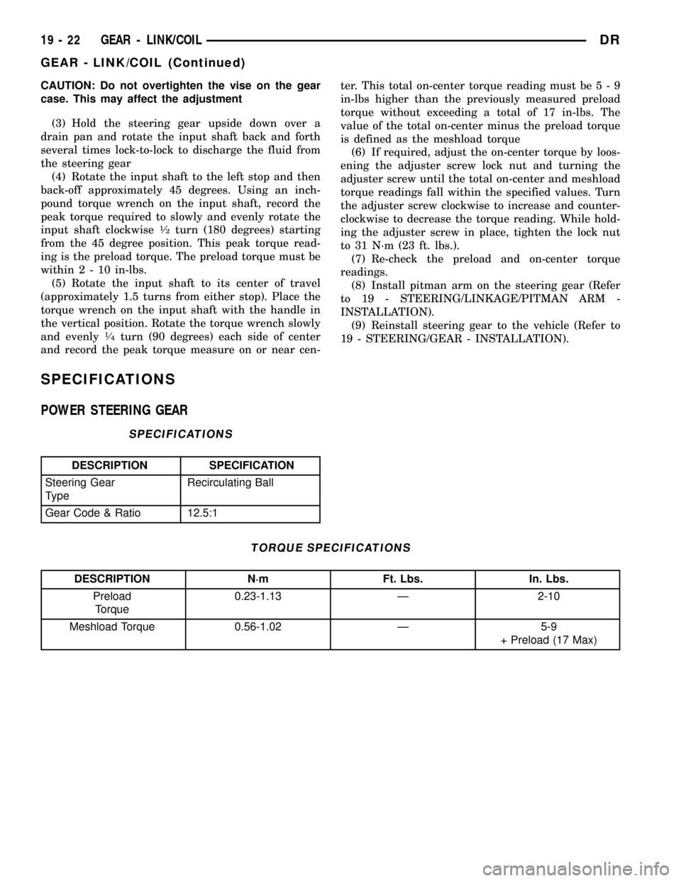
1¤2turn (180 degrees) starting
from the 45 degree position. This peak torque read-
ing is the preload torque. The preload torque must be
within2-10in-lbs.
(5) Rotate the input shaft to its center of travel
(approximately 1.5 turns from either stop). Place the
torque wrench on the input shaft with the handle in
the vertical position. Rotate the torque wrench slowly
and evenly
1¤4turn (90 degrees) each side of center
and record the peak torque measure on or near cen-ter. This total on-center torque reading must be5-9
in-lbs higher than the previously measured preload
torque without exceeding a total of 17 in-lbs. The
value of the total on-center minus the preload torque
is defined as the meshload torque
(6) If required, adjust the on-center torque by loos-
ening the adjuster screw lock nut and turning the
adjuster screw until the total on-center and meshload
torque readings fall within the specified values. Turn
the adjuster screw clockwise to increase and counter-
clockwise to decrease the torque reading. While hold-
ing the adjuster screw in place, tighten the lock nut
to 31 N´m (23 ft. lbs.).
(7) Re-check the preload and on-center torque
readings.
(8) Install pitman arm on the steering gear (Refer
to 19 - STEERING/LINKAGE/PITMAN ARM -
INSTALLATION).
(9) Reinstall steering gear to the vehicle (Refer to
19 - STEERING/GEAR - INSTALLATION).
SPECIFICATIONS
POWER STEERING GEAR
SPECIFICATIONS
DESCRIPTION SPECIFICATION
Steering Gear
TypeRecirculating Ball
Gear Code & Ratio 12.5:1
TORQUE SPECIFICATIONS
DESCRIPTION N´m Ft. Lbs. In. Lbs.
Preload
Torque0.23-1.13 Ð 2-10
Meshload Torque 0.56-1.02 Ð 5-9
+ Preload (17 Max)
19 - 22 GEAR - LINK/COILDR
GEAR - LINK/COIL (Continued)
Page 1678 of 2627

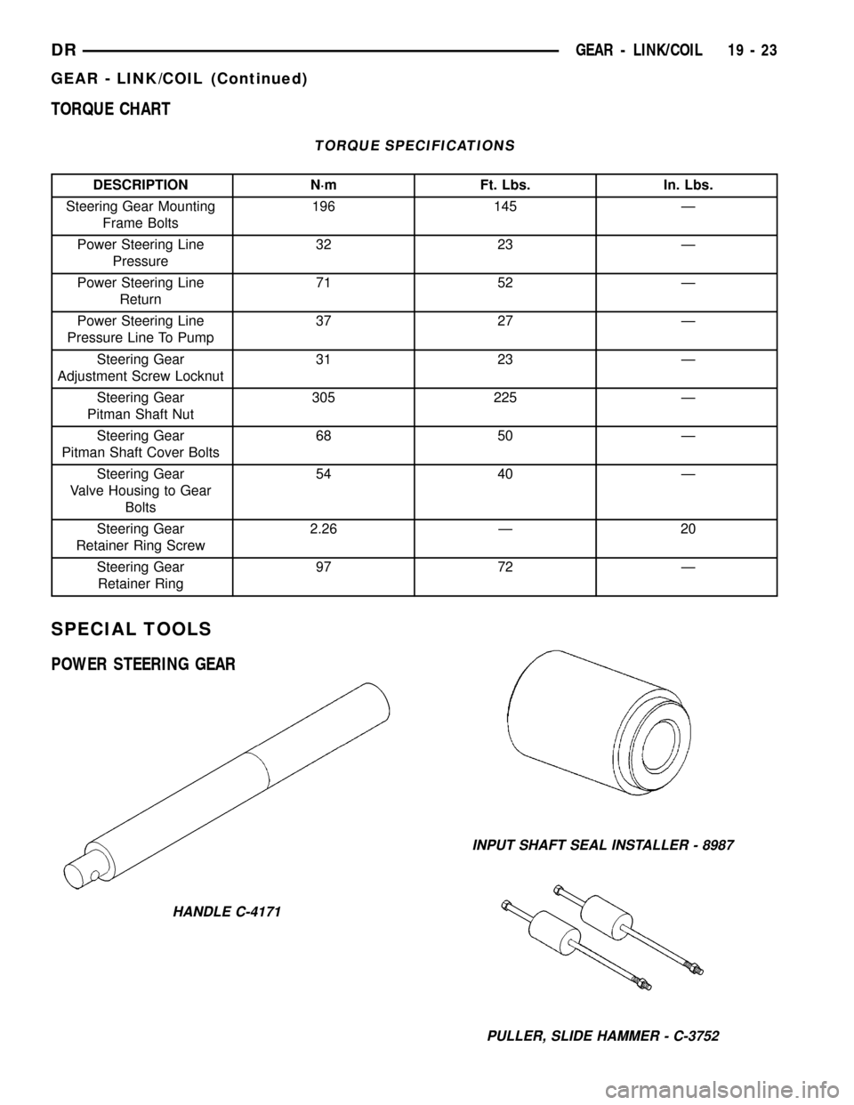
TORQUE CHART
TORQUE SPECIFICATIONS
DESCRIPTION N´m Ft. Lbs. In. Lbs.
Steering Gear Mounting
Frame Bolts196 145 Ð
Power Steering Line
Pressure32 23 Ð
Power Steering Line
Return71 52 Ð
Power Steering Line
Pressure Line To Pump37 27 Ð
Steering Gear
Adjustment Screw Locknut31 23 Ð
Steering Gear
Pitman Shaft Nut305 225 Ð
Steering Gear
Pitman Shaft Cover Bolts68 50 Ð
Steering Gear
Valve Housing to Gear
Bolts54 40 Ð
Steering Gear
Retainer Ring Screw2.26 Ð 20
Steering Gear
Retainer Ring97 72 Ð
SPECIAL TOOLS
POWER STEERING GEAR
HANDLE C-4171
INPUT SHAFT SEAL INSTALLER - 8987
PULLER, SLIDE HAMMER - C-3752
DRGEAR - LINK/COIL 19 - 23
GEAR - LINK/COIL (Continued)