1998 DODGE RAM 1500 Camshaft
[x] Cancel search: CamshaftPage 1415 of 2627
(31)Install the air cleaner resonator and duct work..
(32) Add engine oil to crankcase (Refer to LUBRI-
CATION & MAINTENANCE/FLUID TYPES - SPEC-
IFICATIONS).
(33) Fill cooling system (Refer to 7 - COOLING -
STANDARD PROCEDURE).
(34) Connect battery negative cable.
(35) Start engine and inspect for leaks.
(36) Road test vehicle.
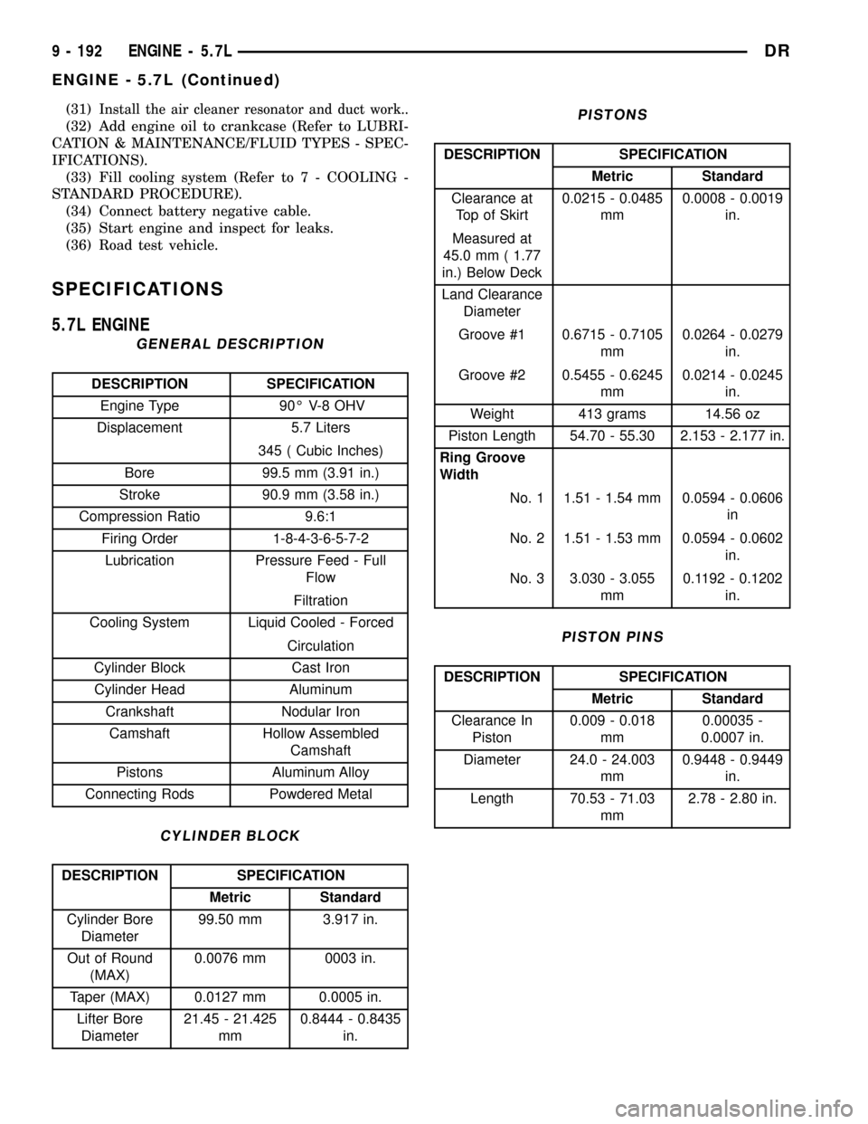
SPECIFICATIONS
5.7L ENGINE
GENERAL DESCRIPTION
DESCRIPTION SPECIFICATION
Engine Type 90É V-8 OHV
Displacement 5.7 Liters
345 ( Cubic Inches)
Bore 99.5 mm (3.91 in.)
Stroke 90.9 mm (3.58 in.)
Compression Ratio 9.6:1
Firing Order 1-8-4-3-6-5-7-2
Lubrication Pressure Feed - Full
Flow
Filtration
Cooling System Liquid Cooled - Forced
Circulation
Cylinder Block Cast Iron
Cylinder Head Aluminum
Crankshaft Nodular Iron
Camshaft Hollow Assembled
Camshaft
Pistons Aluminum Alloy
Connecting Rods Powdered Metal
CYLINDER BLOCK
DESCRIPTION SPECIFICATION
Metric Standard
Cylinder Bore
Diameter99.50 mm 3.917 in.
Out of Round
(MAX)0.0076 mm 0003 in.
Taper (MAX) 0.0127 mm 0.0005 in.
Lifter Bore
Diameter21.45 - 21.425
mm0.8444 - 0.8435
in.
PISTONS
DESCRIPTION SPECIFICATION
Metric Standard
Clearance at
Top of Skirt0.0215 - 0.0485
mm0.0008 - 0.0019
in.
Measured at
45.0 mm ( 1.77
in.) Below Deck
Land Clearance
Diameter
Groove #1 0.6715 - 0.7105
mm0.0264 - 0.0279
in.
Groove #2 0.5455 - 0.6245
mm0.0214 - 0.0245
in.
Weight 413 grams 14.56 oz
Piston Length 54.70 - 55.30 2.153 - 2.177 in.
Ring Groove
Width
No. 1 1.51 - 1.54 mm 0.0594 - 0.0606
in
No. 2 1.51 - 1.53 mm 0.0594 - 0.0602
in.
No. 3 3.030 - 3.055
mm0.1192 - 0.1202
in.
PISTON PINS
DESCRIPTION SPECIFICATION
Metric Standard
Clearance In
Piston0.009 - 0.018
mm0.00035 -
0.0007 in.
Diameter 24.0 - 24.003
mm0.9448 - 0.9449
in.
Length 70.53 - 71.03
mm2.78 - 2.80 in.
9 - 192 ENGINE - 5.7LDR
ENGINE - 5.7L (Continued)
Page 1416 of 2627
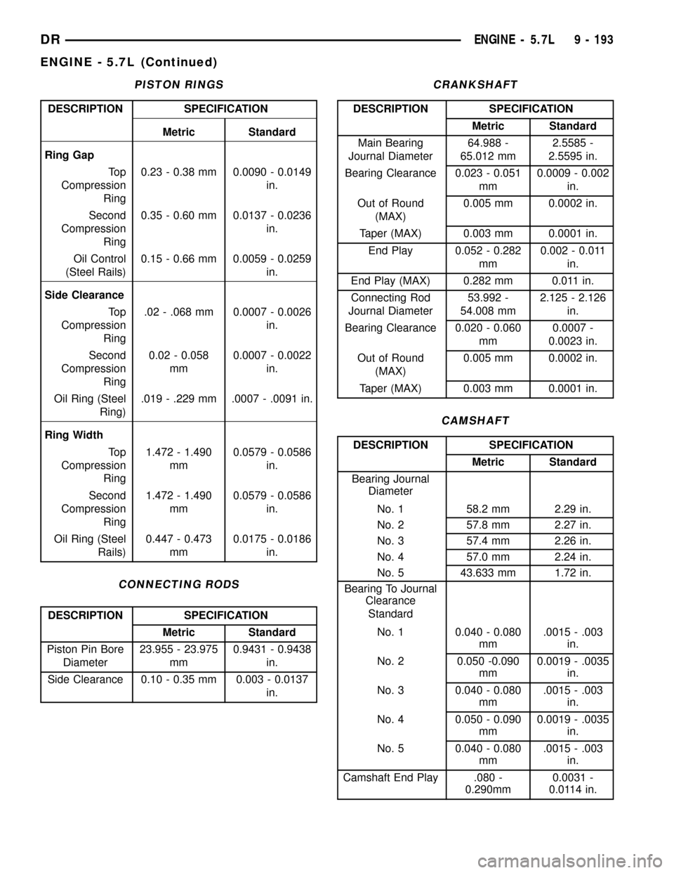
PISTON RINGS
DESCRIPTION SPECIFICATION
Metric Standard
Ring Gap
To p
Compression
Ring0.23 - 0.38 mm 0.0090 - 0.0149
in.
Second
Compression
Ring0.35 - 0.60 mm 0.0137 - 0.0236
in.
Oil Control
(Steel Rails)0.15 - 0.66 mm 0.0059 - 0.0259
in.
Side Clearance
To p
Compression
Ring.02 - .068 mm 0.0007 - 0.0026
in.
Second
Compression
Ring0.02 - 0.058
mm0.0007 - 0.0022
in.
Oil Ring (Steel
Ring).019 - .229 mm .0007 - .0091 in.
Ring Width
To p
Compression
Ring1.472 - 1.490
mm0.0579 - 0.0586
in.
Second
Compression
Ring1.472 - 1.490
mm0.0579 - 0.0586
in.
Oil Ring (Steel
Rails)0.447 - 0.473
mm0.0175 - 0.0186
in.
CONNECTING RODS
DESCRIPTION SPECIFICATION
Metric Standard
Piston Pin Bore
Diameter23.955 - 23.975
mm0.9431 - 0.9438
in.
Side Clearance 0.10 - 0.35 mm 0.003 - 0.0137
in.
CRANKSHAFT
DESCRIPTION SPECIFICATION
Metric Standard
Main Bearing
Journal Diameter64.988 -
65.012 mm2.5585 -
2.5595 in.
Bearing Clearance 0.023 - 0.051
mm0.0009 - 0.002
in.
Out of Round
(MAX)0.005 mm 0.0002 in.
Taper (MAX) 0.003 mm 0.0001 in.
End Play 0.052 - 0.282
mm0.002 - 0.011
in.
End Play (MAX) 0.282 mm 0.011 in.
Connecting Rod
Journal Diameter53.992 -
54.008 mm2.125 - 2.126
in.
Bearing Clearance 0.020 - 0.060
mm0.0007 -
0.0023 in.
Out of Round
(MAX)0.005 mm 0.0002 in.
Taper (MAX) 0.003 mm 0.0001 in.
CAMSHAFT
DESCRIPTION SPECIFICATION
Metric Standard
Bearing Journal
Diameter
No. 1 58.2 mm 2.29 in.
No. 2 57.8 mm 2.27 in.
No. 3 57.4 mm 2.26 in.
No. 4 57.0 mm 2.24 in.
No. 5 43.633 mm 1.72 in.
Bearing To Journal
Clearance
Standard
No. 1 0.040 - 0.080
mm.0015 - .003
in.
No. 2 0.050 -0.090
mm0.0019 - .0035
in.
No. 3 0.040 - 0.080
mm.0015 - .003
in.
No. 4 0.050 - 0.090
mm0.0019 - .0035
in.
No. 5 0.040 - 0.080
mm.0015 - .003
in.
Camshaft End Play .080 -
0.290mm0.0031 -
0.0114 in.
DRENGINE - 5.7L 9 - 193
ENGINE - 5.7L (Continued)
Page 1418 of 2627
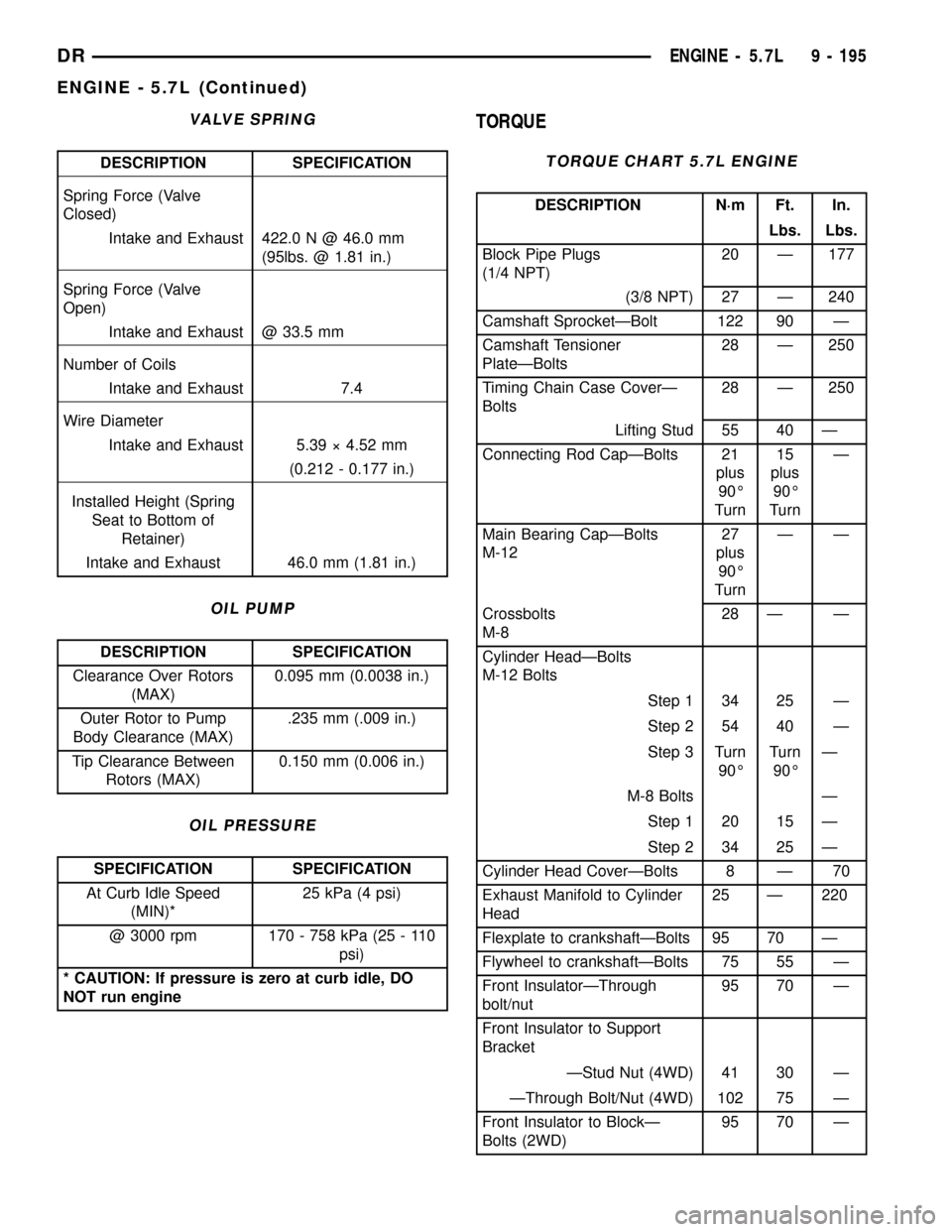
VALVE SPRING
DESCRIPTION SPECIFICATION
Spring Force (Valve
Closed)
Intake and Exhaust 422.0 N @ 46.0 mm
(95lbs. @ 1.81 in.)
Spring Force (Valve
Open)
Intake and Exhaust @ 33.5 mm
Number of Coils
Intake and Exhaust 7.4
Wire Diameter
Intake and Exhaust 5.39 ý 4.52 mm
(0.212 - 0.177 in.)
Installed Height (Spring
Seat to Bottom of
Retainer)
Intake and Exhaust 46.0 mm (1.81 in.)
OIL PUMP
DESCRIPTION SPECIFICATION
Clearance Over Rotors
(MAX)0.095 mm (0.0038 in.)
Outer Rotor to Pump
Body Clearance (MAX).235 mm (.009 in.)
Tip Clearance Between
Rotors (MAX)0.150 mm (0.006 in.)
OIL PRESSURE
SPECIFICATION SPECIFICATION
At Curb Idle Speed
(MIN)*25 kPa (4 psi)
@ 3000 rpm 170 - 758 kPa (25 - 110
psi)
* CAUTION: If pressure is zero at curb idle, DO
NOT run engine
TORQUE
TORQUE CHART 5.7L ENGINE
DESCRIPTION N´m Ft. In.
Lbs. Lbs.
Block Pipe Plugs
(1/4 NPT)20 Ð 177
(3/8 NPT) 27 Ð 240
Camshaft SprocketÐBolt 122 90 Ð
Camshaft Tensioner
PlateÐBolts28 Ð 250
Timing Chain Case CoverÐ
Bolts28 Ð 250
Lifting Stud 55 40 Ð
Connecting Rod CapÐBolts 21
plus
90É
Turn15
plus
90É
TurnÐ
Main Bearing CapÐBolts
M-1227
plus
90É
TurnÐÐ
Crossbolts
M-828 Ð Ð
Cylinder HeadÐBolts
M-12 Bolts
Step 1 34 25 Ð
Step 2 54 40 Ð
Step 3 Turn
90ÉTurn
90ÉÐ
M-8 Bolts Ð
Step 1 20 15 Ð
Step 2 34 25 Ð
Cylinder Head CoverÐBolts 8 Ð 70
Exhaust Manifold to Cylinder
Head25 Ð 220
Flexplate to crankshaftÐBolts 95 70 Ð
Flywheel to crankshaftÐBolts 75 55 Ð
Front InsulatorÐThrough
bolt/nut95 70 Ð
Front Insulator to Support
Bracket
ÐStud Nut (4WD) 41 30 Ð
ÐThrough Bolt/Nut (4WD) 102 75 Ð
Front Insulator to BlockÐ
Bolts (2WD)95 70 Ð
DRENGINE - 5.7L 9 - 195
ENGINE - 5.7L (Continued)
Page 1428 of 2627
ENGINE BLOCK
CLEANING
Thoroughly clean the oil pan and engine block gas-
ket surfaces.
Use compressed air to clean out:
²The galley at the oil filter adaptor hole.
²The front and rear oil galley holes.
²The feed holes for the crankshaft main bearings.
Once the block has been completely cleaned, apply
Loctite PST pipe sealant with Teflon 592 to the
threads of the front and rear oil galley plugs. Tighten
the 1/4 inch NPT plugs to 20 N´m (177 in. lbs.)
torque. Tighten the 3/8 inch NPT plugs to 27 N´m
(240 in. lbs.) torque.
INSPECTION
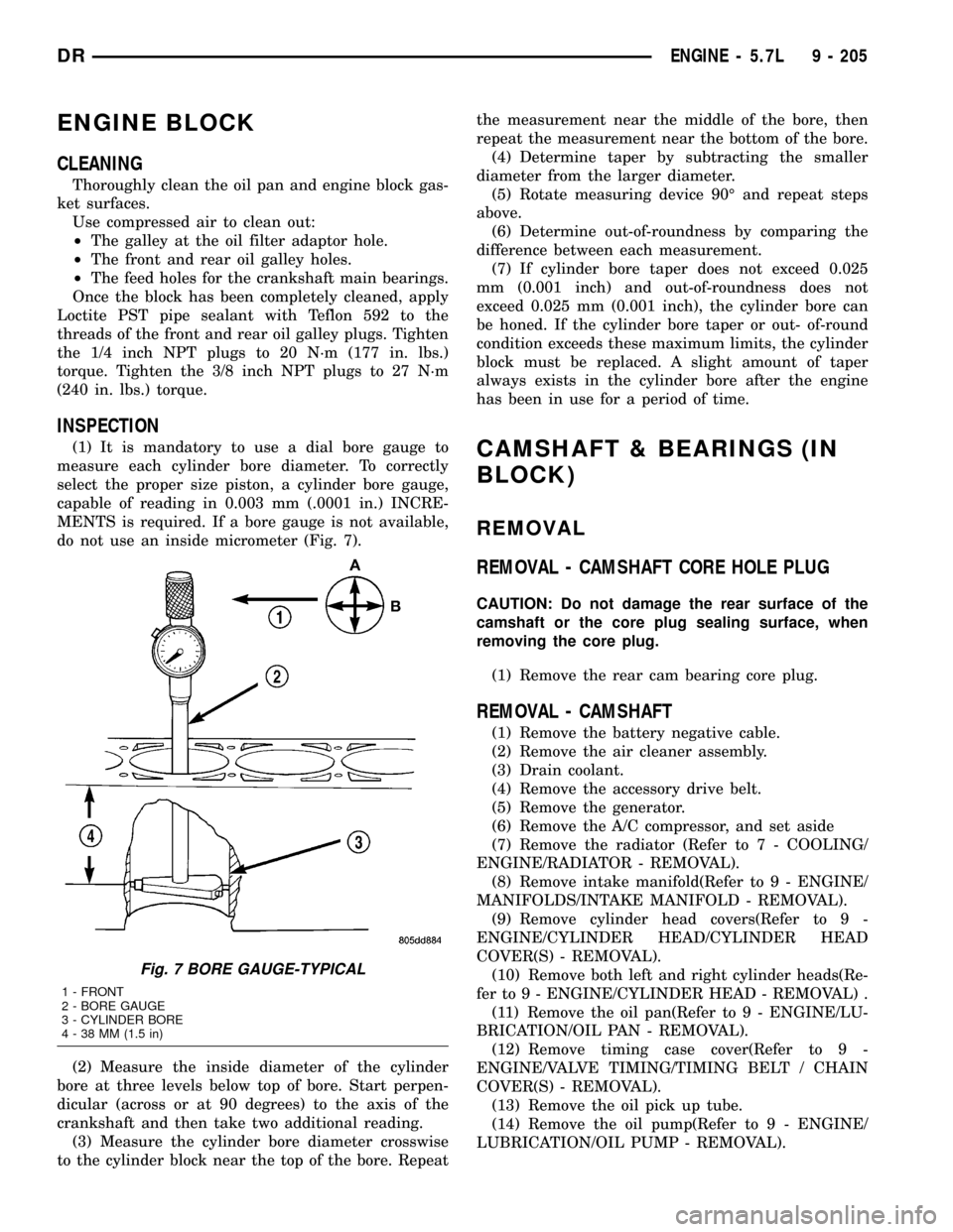
(1) It is mandatory to use a dial bore gauge to
measure each cylinder bore diameter. To correctly
select the proper size piston, a cylinder bore gauge,
capable of reading in 0.003 mm (.0001 in.) INCRE-
MENTS is required. If a bore gauge is not available,
do not use an inside micrometer (Fig. 7).
(2) Measure the inside diameter of the cylinder
bore at three levels below top of bore. Start perpen-
dicular (across or at 90 degrees) to the axis of the
crankshaft and then take two additional reading.
(3) Measure the cylinder bore diameter crosswise
to the cylinder block near the top of the bore. Repeatthe measurement near the middle of the bore, then
repeat the measurement near the bottom of the bore.
(4) Determine taper by subtracting the smaller
diameter from the larger diameter.
(5) Rotate measuring device 90É and repeat steps
above.
(6) Determine out-of-roundness by comparing the
difference between each measurement.
(7) If cylinder bore taper does not exceed 0.025
mm (0.001 inch) and out-of-roundness does not
exceed 0.025 mm (0.001 inch), the cylinder bore can
be honed. If the cylinder bore taper or out- of-round
condition exceeds these maximum limits, the cylinder
block must be replaced. A slight amount of taper
always exists in the cylinder bore after the engine
has been in use for a period of time.CAMSHAFT & BEARINGS (IN
BLOCK)
REMOVAL
REMOVAL - CAMSHAFT CORE HOLE PLUG
CAUTION: Do not damage the rear surface of the
camshaft or the core plug sealing surface, when
removing the core plug.
(1) Remove the rear cam bearing core plug.
REMOVAL - CAMSHAFT
(1) Remove the battery negative cable.
(2) Remove the air cleaner assembly.
(3) Drain coolant.
(4) Remove the accessory drive belt.
(5) Remove the generator.
(6) Remove the A/C compressor, and set aside
(7) Remove the radiator (Refer to 7 - COOLING/
ENGINE/RADIATOR - REMOVAL).
(8) Remove intake manifold(Refer to 9 - ENGINE/
MANIFOLDS/INTAKE MANIFOLD - REMOVAL).
(9) Remove cylinder head covers(Refer to 9 -
ENGINE/CYLINDER HEAD/CYLINDER HEAD
COVER(S) - REMOVAL).
(10) Remove both left and right cylinder heads(Re-
fer to 9 - ENGINE/CYLINDER HEAD - REMOVAL) .
(11) Remove the oil pan(Refer to 9 - ENGINE/LU-
BRICATION/OIL PAN - REMOVAL).
(12) Remove timing case cover(Refer to 9 -
ENGINE/VALVE TIMING/TIMING BELT / CHAIN
COVER(S) - REMOVAL).
(13) Remove the oil pick up tube.
(14) Remove the oil pump(Refer to 9 - ENGINE/
LUBRICATION/OIL PUMP - REMOVAL).
Fig. 7 BORE GAUGE-TYPICAL
1 - FRONT
2 - BORE GAUGE
3 - CYLINDER BORE
4 - 38 MM (1.5 in)
DRENGINE - 5.7L 9 - 205
Page 1429 of 2627
(15) Remove timing chain(Refer to 9 - ENGINE/
VALVE TIMING/TIMING BELT/CHAIN AND
SPROCKETS - REMOVAL).
(16) Remove camshaft tensioner/thrust plate
assembly.
NOTE: Identify tappets to ensure installation in orig-
inal location.
(17) Remove the retainer assembly and tappets.
(18) Install a long bolt into front of camshaft to aid
in removal of the camshaft. Remove camshaft, being
careful not to damage cam bearings with the cam
lobes.
INSPECTION
(1) The cam bearings are not serviceable. Do not
attempt to replace cam bearings for any reason.
INSTALLATION
INSTALLATION - CAMSHAFT CORE HOLE PLUG
CAUTION: The new core hole plug must be installed
to the proper depth or camshaft damage could
develope. The plug must be installed squarely in
the bore.
(1) Install a new core hole plug at the rear of cam-
shaft, using special tool # 9048. Clean plug and apply
mopartlock and seal adhesive to the edge of the
plug, before installing. The plug must be installed to
a depth of+/-0.25mm from the end of the machined
bevel, that is the end of the bevel that is closest to
the cam bearing.
INSTALLATION - CAMSHAFT
(1) Lubricate camshaft lobes and camshaft bearing
journals and insert the camshaft
(2) Install camshaft Tensioner plate assembly.
Tighten bolts to 28 N´m (250 in. lbs.) torque.
(3) Install timing chain and sprockets(Refer to 9 -
ENGINE/VALVE TIMING/TIMING BELT/CHAIN
AND SPROCKETS - INSTALLATION) .
(4) Measure camshaft end play(Refer to 9 -
ENGINE - SPECIFICATIONS). If not within limits
install a new thrust plate.
(5) Install the oil pump(Refer to 9 - ENGINE/LU-
BRICATION/OIL PUMP - INSTALLATION).
(6) Install the oil pick up tube.
(7) Each tappet reused must be installed in the
same position from which it was removed.When
camshaft is replaced, all of the tappets must be
replaced.(8) Install the tappets and retainer assembly(Refer
to 9 - ENGINE/ENGINE BLOCK/HYDRAULIC LIFT-
ERS (CAM IN BLOCK) - INSTALLATION).
(9) Install both left and right cylinder heads(Refer
to 9 - ENGINE/CYLINDER HEAD - INSTALLA-
TION) .
(10) Install pushrods
(11) Install rocker arms(Refer to 9 - ENGINE/CYL-
INDER HEAD/ROCKER ARM / ADJUSTER ASSY -
INSTALLATION).
(12) Install timing case cover(Refer to 9 -
ENGINE/VALVE TIMING/TIMING BELT / CHAIN
COVER(S) - INSTALLATION).
(13) Install the oil pan(Refer to 9 - ENGINE/LU-
BRICATION/OIL PAN - INSTALLATION).
(14) Install cylinder head covers(Refer to 9 -
ENGINE/CYLINDER HEAD/CYLINDER HEAD
COVER(S) - INSTALLATION).
(15) Install intake manifold(Refer to 9 - ENGINE/
MANIFOLDS/INTAKE MANIFOLD - INSTALLA-
TION).
(16) Install the A/C compressor, and set aside
(17) Install the generator.
(18) Install the accessory drive belt.
(19) Install the radiator (Refer to 7 - COOLING/
ENGINE/RADIATOR - INSTALLATION).
(20) Install the air cleaner assembly.
(21) Install the battery negative cable.
(22) Refill coolant.
(23) Refill engine oil.
(24) Start engine and check for leaks.
CRANKSHAFT
REMOVAL
(1) Remove the vibration damper (Refer to 9 -
ENGINE/ENGINE BLOCK/VIBRATION DAMPER -
REMOVAL).
(2) Remove the oil pan(Refer to 9 - ENGINE/LU-
BRICATION/OIL PAN - REMOVAL).
(3) Remove the oil pump pickup.
(4) Remove the windage tray/oil pan gasket.
(5) Remove the timing chain cover(Refer to 9 -
ENGINE/VALVE TIMING/TIMING BELT / CHAIN
COVER(S) - REMOVAL).
(6) Remove the oil pump(Refer to 9 - ENGINE/LU-
BRICATION/OIL PUMP - REMOVAL).
(7) Remove the timing drive(Refer to 9 - ENGINE/
VALVE TIMING/TIMING BELT/CHAIN AND
SPROCKETS - REMOVAL).
(8) Identify rod bearing caps before removal.
Remove rod bearing caps with bearings.
(9) Identify main bearing caps before removal.
Remove main bearing caps and bearings one at a
time.
9 - 206 ENGINE - 5.7LDR
CAMSHAFT & BEARINGS (IN BLOCK) (Continued)
Page 1432 of 2627
CRANKSHAFT OIL SEAL -
REAR
DIAGNOSIS AND TESTING - REAR SEAL AREA
LEAKS
Since it is sometimes difficult to determine the
source of an oil leak in the rear seal area of the
engine, a more involved inspection is necessary. The
following steps should be followed to help pinpoint
the source of the leak.
If the leakage occurs at the crankshaft rear oil seal
area:
(1) Disconnect the battery.
(2) Raise the vehicle.
(3) Remove torque converter or clutch housing
cover and inspect rear of block for evidence of oil.
Use a black light to check for the oil leak:
(a) Circular spray pattern generally indicates
seal leakage or crankshaft damage.
(b) Where leakage tends to run straight down,
possible causes are a porous block, camshaft bore
cup plugs, oil galley pipe plugs, oil filter runoff,
and main bearing cap to cylinder block mating sur-
faces. See Engine, for proper repair procedures of
these items.
(4) If no leaks are detected, pressurized the crank-
case as outlined in the section, Inspection (Engine oil
Leaks in general)
CAUTION: Do not exceed 20.6 kPa (3 psi).
(5) If the leak is not detected, very slowly turn the
crankshaft and watch for leakage. If a leak is
detected between the crankshaft and seal while
slowly turning the crankshaft, it is possible the
crankshaft seal surface is damaged. The seal area on
the crankshaft could have minor nicks or scratches
that can be polished out with emery cloth.
CAUTION: Use extreme caution when crankshaft
polishing is necessary to remove minor nicks or
scratches. The crankshaft seal flange is specially
machined to complement the function of the rear oil
seal.
(6) For bubbles that remain steady with shaft
rotation, no further inspection can be done until dis-
assembled. (Refer to 9 - ENGINE - DIAGNOSIS AND
TESTING), under the Oil Leak row, for components
inspections on possible causes and corrections.
(7) After the oil leak root cause and appropriate
corrective action have been identified, (Refer to 9 -
ENGINE/ENGINE BLOCK/CRANKSHAFT OIL
SEAL - REAR - REMOVAL).
REMOVAL
NOTE: This procedure can be performed in vehicle.
(1) If being preformed in vehicle, remove the
transmission.
(2) Remove the flexplate (Refer to 9 - ENGINE/
ENGINE BLOCK/FLEX PLATE - REMOVAL).
NOTE: The crankshaft oil seal CAN NOT be reused
after removal.
NOTE: The crankshaft rear oil seal remover Special
Tool 8506 must be installed deeply into the seal.
Continue to tighten the removal tool into the seal
until the tool can not be turned farther. Failure to
install tool correctly the first time will cause tool to
pull free of seal without removing seal from engine.
(3) Using Special Tool 8506, remove the crankshaft
rear oil seal.
INSTALLATION
CAUTION: The rear seal must be installed dry for
proper operation. Do not lubricate the seal lip or
outer edge.
(1) Position the plastic seal guide onto the crank-
shaft rear face. Then position the crankshaft rear oil
seal onto the guide.
(2) Using Special Tools 8349 Crankshaft Rear Oil
Seal Installer and C-4171 Driver Handle, with a
hammer, tap the seal into place. Continue to tap on
the driver handle until the seal installer seats
against the cylinder block crankshaft bore.
(3) Install the flexplate.
(4) Install the transmission.
CRANKSHAFT REAR OIL SEAL
RETAINER
REMOVAL
(1) Disconnect negative cable from battery.
(2) Remove the transmission.
(3) Remove the drive plate / flywheel.
(4) Remove the oil pan (Refer to 9 - ENGINE/LU-
BRICATION/OIL PAN - REMOVAL).
(5) Remove the rear oil seal retainer mounting
bolts.
(6) Carefully remove the retainer from the engine
block.
DRENGINE - 5.7L 9 - 209
Page 1434 of 2627
REMOVAL
(1) Disconnect the negative cable from the battery.
(2) Remove the air cleaner(Refer to 9 - ENGINE/
AIR INTAKE SYSTEM - REMOVAL).
(3) Remove intake manifold(Refer to 9 - ENGINE/
MANIFOLDS/INTAKE MANIFOLD - REMOVAL).
(4) Remove cylinder head cover(Refer to 9 -
ENGINE/CYLINDER HEAD/CYLINDER HEAD
COVER(S) - REMOVAL).
(5) Remove rocker arm assembly and push rod-
s(Refer to 9 - ENGINE/CYLINDER HEAD/ROCKER
ARM / ADJUSTER ASSY - REMOVAL). Identify
push rods to ensure installation in original location.
(6) Remove the cylinder head(Refer to 9 -
ENGINE/CYLINDER HEAD - REMOVAL).
(7) Remove bolt from tappet guide holder.
(8) Remove tappet guide holder.
(9) Pull tappet out of bore with a twisting motion.
If all tappets are to be removed and reused, identify
tappets to ensure installation in original location.
(10) Check camshaft lobes for abnormal wear.
INSTALLATION
(1) Lubricate tappets.
(2) Install tappets in their original positions.
(3)
Install tappet guide holder. Install the tappet
guide holder bolt and tighten to 12 N´m (106 in. lbs.)
torque.
(4) Install cylinder head(Refer to 9 - ENGINE/
CYLINDER HEAD - INSTALLATION).
(5) Install pushrods and rocker arm assembly(Re-
fer to 9 - ENGINE/CYLINDER HEAD/ROCKER
ARM / ADJUSTER ASSY - INSTALLATION).
(6) Install cylinder head cover(Refer to 9 -
ENGINE/CYLINDER HEAD/CYLINDER HEAD
COVER(S) - INSTALLATION).
(7)
Install intake manifold(Refer to 9 - ENGINE/
MANIFOLDS/INTAKE MANIFOLD - INSTALLATION).
(8) Install the air cleaner(Refer to 9 - ENGINE/
AIR INTAKE SYSTEM - INSTALLATION).
(9) Connect the negative cable to the battery.
CAUTION: To prevent damage to valve mechanism,
engine must not be run above fast idle until all
hydraulic tappets have filled with oil and have
become quiet.
(10) Road test vehicle and check for leaks.
PISTON & CONNECTING ROD
DESCRIPTION
CAUTION: Do not use a metal stamp to mark con-
necting rods as damage may result, instead use ink
or a scratch awl.The pistons are made of a high strength aluminum
alloy. Piston skirts are coated with a solid lubricant
(Molykote) to reduce friction and provide scuff resis-
tance. The piston top ring groove and land is anod-
ized. The connecting rods are made of forged
powdered metal, with a ªfractured capº design. A
pressed fit piston pin is used to attach the piston and
connecting rod.
STANDARD PROCEDUREÐPISTON FITTING
(1) To correctly select the proper size piston, a cyl-
inder bore gauge, capable of reading in 0.003 mm (
.0001 in.) INCREMENTS is required. If a bore gauge
is not available, do not use an inside micrometer.
(2) Measure the inside diameter of the cylinder
bore at a point 38.0 mm (1.5 inches) below top of
bore. Start perpendicular (across or at 90 degrees) to
the axis of the crankshaft at point A and then take
an additional bore reading 90 degrees to that at point
B (Fig. 11).
(3) The coated pistons will be serviced with the
piston pin and connecting rod pre-assembled. The
piston-rod assembly is specific for the left cylinder
bank ( odd numbered) and the right cylinder bank (
even numbered) and must not be interchanged.
(4) The coating material is applied to the piston
after the final piston machining process. Measuring
the outside diameter of a coated piston will not pro-
vide accurate results (Fig. 10). Therefore measuring
the inside diameter of the cylinder bore with a dial
Bore Gauge isMANDATORY. To correctly select the
proper size piston, a cylinder bore gauge capable of
reading in 0.003 mm (.0001 in.) increments is
required.
Fig. 10 MOLY COATED PISTON
1 - MOLY COATED
2 - MOLY COATED
DRENGINE - 5.7L 9 - 211
HYDRAULIC TAPPETS (Continued)
Page 1445 of 2627
If the leakage occurs at the crankshaft rear oil seal
area:
(1) Disconnect the battery.
(2) Raise the vehicle.
(3) Remove torque converter or clutch housing
cover and inspect rear of block for evidence of oil.
Use a black light to check for the oil leak:
(a) Circular spray pattern generally indicates
seal leakage or crankshaft damage.
(b) Where leakage tends to run straight down,
possible causes are a porous block, distributor seal,
camshaft bore cup plugs oil galley pipe plugs, oil
filter runoff, and main bearing cap to cylinder
block mating surfaces.
(4) If no leaks are detected, pressurize the crank-
case as outlined in the, Inspection (Engine oil Leaks
in general)
CAUTION: Do not exceed 20.6 kPa (3 psi).
(5) If the leak is not detected, very slowly turn the
crankshaft and watch for leakage. If a leak is
detected between the crankshaft and seal while
slowly turning the crankshaft, it is possible the
crankshaft seal surface is damaged. The seal area on
the crankshaft could have minor nicks or scratches
that can be polished out with emery cloth.
CAUTION: Use extreme caution when crankshaft
polishing is necessary to remove minor nicks and
scratches. The crankshaft seal flange is especially
machined to complement the function of the rear oil
seal.
(6) For bubbles that remain steady with shaft
rotation, no further inspection can be done until dis-
assembled.
OIL
STANDARD PROCEDURE - ENGINE OIL
SERVICE
WARNING: NEW OR USED ENGINE OIL CAN BE
IRRITATING TO THE SKIN. AVOID PROLONGED OR
REPEATED SKIN CONTACT WITH ENGINE OIL.
CONTAMINANTS IN USED ENGINE OIL, CAUSED BY
INTERNAL COMBUSTION, CAN BE HAZARDOUS TO
YOUR HEALTH. THOROUGHLY WASH EXPOSED
SKIN WITH SOAP AND WATER. DO NOT WASH
SKIN WITH GASOLINE, DIESEL FUEL, THINNER, OR
SOLVENTS, HEALTH PROBLEMS CAN RESULT. DO
NOT POLLUTE, DISPOSE OF USED ENGINE OIL
PROPERLY.
ENGINE OIL SPECIFICATION
CAUTION: Do not use non-detergent or straight
mineral oil when adding or changing crankcase
lubricant. Engine failure can result.
API SERVICE GRADE CERTIFIED
Use an engine oil that is API Service Grade Certi-
fied. MOPARtprovides engine oils that conform to
this service grade.
SAE VISCOSITY
An SAE viscosity grade is used to specify the vis-
cosity of engine oil. Use only engine oils with multi-
ple viscosities such as 5W-30 in the 5.7L engines.
These are specified with a dual SAE viscosity grade
which indicates the cold-to-hot temperature viscosity
range. Select an engine oil that is best suited to your
particular temperature range and variation.
ENERGY CONSERVING OIL
An Energy Conserving type oil is recommended for
gasoline engines. The designation of ENERGY CON-
SERVING is located on the label of an engine oil con-
tainer.
CONTAINER IDENTIFICATION
Standard engine oil identification notations have
been adopted to aid in the proper selection of engine
oil. The identifying notations are located on the label
of engine oil plastic bottles and the top of engine oil
cans (Fig. 28).
OIL LEVEL INDICATOR (DIPSTICK)
The engine oil level indicator is located at the left
hand of the engine on the 5.7L engines.
CRANKCASE OIL LEVEL INSPECTION
CAUTION: Do not overfill crankcase with engine oil,
pressure loss or oil foaming can result.
Inspect engine oil level approximately every 800
kilometers (500 miles). Unless the engine has exhib-
ited loss of oil pressure, run the engine for about ten
Fig. 28 API SYMBOL
9 - 222 ENGINE - 5.7LDR
LUBRICATION (Continued)