1998 DODGE RAM 1500 section 5
[x] Cancel search: section 5Page 1446 of 2627
minutes before checking oil level. Checking engine oil
level on a cold engine is not accurate.
To ensure proper lubrication of an engine, the
engine oil must be maintained at an acceptable level.
The acceptable levels are indicated between the ADD
and SAFE marks on the engine oil dipstick.
(1) Position vehicle on level surface.
(2) With engine OFF, allow approximately five
minutes for oil to settle to bottom of crankcase,
remove engine oil dipstick.
(3) Wipe dipstick clean.
(4) Install dipstick and verify it is seated in the
tube.
(5) Remove dipstick, with handle held above the
tip, take oil level reading.
(6) Add oil only if level is below the ADD mark on
dipstick.
ENGINE OIL CHANGE
Change engine oil at mileage and time intervals
described in Maintenance Schedules(Refer to LUBRI-
CATION & MAINTENANCE/MAINTENANCE
SCHEDULES - DESCRIPTION).
Run engine until achieving normal operating tem-
perature.
(1) Position the vehicle on a level surface and turn
engine off.
(2) Hoist and support vehicle on safety stands.
(3) Remove oil fill cap.
(4) Place a suitable drain pan under crankcase
drain.
(5) Remove drain plug from crankcase and allow
oil to drain into pan. Inspect drain plug threads for
stretching or other damage. Replace drain plug if
damaged.
(6) Install drain plug in crankcase. Torque to 34
N´m ( 25 ft. lbs.).
(7) Lower vehicle and fill crankcase with specified
type and amount of engine oil described in this sec-
tion.
(8) Install oil fill cap.
(9) Start engine and inspect for leaks.
(10) Stop engine and inspect oil level.
USED ENGINE OIL DISPOSAL
Care should be exercised when disposing used
engine oil after it has been drained from a vehicle
engine. Refer to the WARNING at beginning of this
section.
OIL FILTER
REMOVAL
All engines are equipped with a high quality full-
flow, disposable type oil filter. DaimlerChrysler Cor-
poration recommends a Mopartor equivalent oil
filter be used.
(1) Position a drain pan under the oil filter.
(2) Using a suitable oil filter wrench loosen filter.
(3) Rotate the oil filter counterclockwise to remove
it from the cylinder block oil filter boss.
(4) When filter separates from cylinder block oil
filter boss, tip gasket end upward to minimize oil
spill. Remove filter from vehicle.
NOTE: Make sure filter gasket was removed with fil-
ter.
(5) With a wiping cloth, clean the gasket sealing
surface of oil and grime.
INSTALLATION
(1) Lightly lubricate oil filter gasket with engine
oil.
(2) Thread filter onto adapter nipple. When gasket
makes contact with sealing surface, (Fig. 29) hand
tighten filter one half turn, or 180É,do not over
tighten.
(3) Add oil, verify crankcase oil level and start
engine. Inspect for oil leaks.
Fig. 29 Oil Filter Sealing Surface - Typical
1 - SEALING SURFACE
2 - RUBBER GASKET
3 - OIL FILTER
DRENGINE - 5.7L 9 - 223
OIL (Continued)
Page 1464 of 2627
(10) Drain engine oil. Remove and discard the oil
filter (Refer to 9 - ENGINE/LUBRICATION/OIL FIL-
TER - REMOVAL).
(11) Install the drain plug. Tighten the plug to 50
N´m (37 ft. lbs.) torque.
(12) Install a new oil filter (Refer to 9 - ENGINE/
LUBRICATION/OIL FILTER - INSTALLATION).
(13) Fill engine crankcase with the specified
amount and grade of oil (Refer to LUBRICATION &
MAINTENANCE/FLUID TYPES - SPECIFICA-
TIONS).
(14) Connect the negative cable(s) to the battery.
(15) Start the engine and check for any leaks.
REMOVAL
REMOVAL - ENGINE
(1) Disconnect both battery negative cables.
(2) Disconnect engine grid heater harness at grid
heater relays.
(3) Disconnect electrical connections from rear of
alternator.
(4) Recover A/C refrigerant. (Refer to 24 - HEAT-
ING & AIR CONDITIONING/PLUMBING - STAN-
DARD PROCEDURE).
(5) Raise vehicle on a hoist.
(6) Drain engine coolant (Refer to 7 - COOLING -
STANDARD PROCEDURE).
(7) Remove engine oil drain plug and drain engine
oil.
(8) Reinstall drain plug. Tighten to 50N´m (37 ft.
lbs.) torque.
(9) Lower the vehicle.
(10) Remove fan/drive assembly. Refer to Section 7
± Fan/Drive Removal
(11) Remove radiator upper hose.
(12) Remove upper fan shroud mounting bolts.
(13) Disconnect the coolant recovery bottle hose
from the radiator fill neck and remove bottle.
(14) Using a 36mm wrench, remove viscous fan/
drive assembly. (Refer to 7 - COOLING/ENGINE/RA-
DIATOR FAN - REMOVAL).
(15) Remove cooling fan and shroud together.
(16) Disconnect heater core supply and return
hoses from the cylinder head fitting and coolant pipe.
(17) Raise vehicle on a hoist.
(18) Remove transmission and transfer case (if
equipped).
(19) Disconnect exhaust pipe from turbocharger
extension pipe.
(20) Disconnect engine harness to vehicle harness
connectors.
(21) Remove starter motor (Refer to 8 - ELECTRI-
CAL/STARTING/STARTER MOTOR - REMOVAL).(22) Remove flywheel/flexplate.
(23) Remove transmission adapter
(24) Disconnect A/C suction/discharge hose from
the rear of the A/C compressor.
(25) Lower vehicle.
(26) Disconnect lower radiator hose from radiator
outlet.
(27) Automatic transmission models:
(28) Disconnect transmission oil cooler lines from
in front of radiator using special tool #6931
(29) Remove radiator. (Refer to 7 - COOLING/EN-
GINE/RADIATOR - REMOVAL).
(30) If A/C equipped, disconnect A/C condenser
refrigerant lines.
(31) Disconnect charge air cooler piping.
(32) Remove charge air cooler mounting bolts.
(33) Remove charge air cooler (and A/C condenser
if equipped) from vehicle.
(34) Remove damper and speed indicator ring from
front of engine.
(35) Disconnect engine block heater connector.
(36) Disconnect A/C compressor and pressure sen-
sor electrical connectors.
(37) Remove the passenger battery ground cable
from the engine block. Remove the driver side bat-
tery ground cable from the engine block.
(38) Remove power steering pump from engine by
removing 3 bolts.
(39) Remove accelerator linkage cover.
(40) Disconnect cables from on-engine APPS.
(41) Disconnect the ECM power connector.
(42) Disconnect the ECM ground wire from the
hydroform screw.
(43) Disconnect the fuel supply and return hoses.
(44) Remove the cylinder head cover. (Refer to 9 -
ENGINE/CYLINDER HEAD/CYLINDER HEAD
COVER(S) - REMOVAL).
(45) Disconnect the 3 injector harness connectors
at the rocker housing. Disconnect the wire harnesses
from the injectors.
(46) Remove the rear engine lift bracket.
(47) Remove cylinder #4, #5, and #6 intake and
exhaust rocker arms, pedestals, and push tubes. Note
the original location for re-assembly.
(48) Loosen #6 fuel line shield bolts and rotate
shield out of the way.
(49) Remove cylinder #5 and #6 high pressure fuel
lines. Remove the fuel connector tube nut and fuel
connector tube. Remove cylinder #5 and #6 fuel injec-
tor.
(50) Remove rocker housing.
DRENGINE 5.9L DIESEL 9 - 241
ENGINE 5.9L DIESEL (Continued)
Page 1466 of 2627
(8) Replace injector o-ring and sealing washer on
injectors #5 and #6. Install injectors and torque using
the following steps:
²Step 1ÐInstall injector hold-down capscrews
and torque to 5 N´m (44 in. lbs.) torque.
²Step 2ÐLoosen injector hold-down capscrews.
²Step 3ÐInstall HPC connector tube and nut.
Torque nut to 15 N´m (11 ft. lbs.) torque.
²Step 4ÐTorque injector hold-down capscrews to
10 N´m (89 in. lbs.) torque.
²Step 5ÐTorque HPC connector tube nut to 50
N´m (37 ft. lbs.) torque.
(9) Install #5 and #6 high pressure fuel lines. Fol-
low correct torque sequence per section 14. Torque
fuel line fittings to 30 N-m (22 ft-lb). Torque brace
capscrew to 24 N-m (18 ft-lb).
(10) Install rear engine lift bracket. Torque to 77
N-m (57 ft-lb).
(11) Install push tubes, rocker arms, and pedestals
for cylinders #4, #5, and #6. Torque the mounting
bolts to 36 N-m (27 ft-lbs).
(12) Reset valve lash on cylinders #4, #5, and #6.
Torque adjusting nuts to 24 N-m (18 ft-lbs).
(13) Install cylinder head cover. Torque to 24 N-m
(18 ft-lbs).(Refer to 9 - ENGINE/CYLINDER HEAD -
INSTALLATION).
(14) Connect breather tube and lube oil drain tube
to breather housing cover. Install breather housing.
Torque capscrews to 24 N-m (18 ft-lbs)
(15) Connect fuel supply and return hoses.
(16) Connect ECM ground to hydroform screw.
Connect ECM power connector.
(17) Install the APPS cable(s) to the APPS. Install
the throttle linkage cover.
(18) Install the power steering pump.
(19) Install the damper and speed indicator ring.
Torque to 40 N-m (30 ft-lb) plus 60 degrees.
(20) Connect the engine block heater connection.
(21) Connect the A/C compressor and pressure sen-
sor connectors
(22) Install the charge air cooler and a/c condenser
(if equipped). Install and tighten the charge air
cooler mounting bolts to 2 N-m (17 in-lbs).
(23) Connect the charge air cooler piping. Torque
all clamps to 8 N-m (72 in-lbs).
(24) Connect the a/c refrigerant lines to the a/c
condenser (if equipped).
(25) Install the radiator upper support panel.
(26) Install radiator.
(27) Connect the transmission quick-connect oil
cooler lines.(28) Raise vehicle.
(29) Connect a/c compressor suction/discharge hose
(if equipped).
(30) Install the radiator lower hose and clamps.
(31) Install the battery negative cables to the
engine block on the driver and passenger side.
(32) Install the transmission adapter with a new
camshaft rectangular ring seal. Torque to 77 N-m (57
ft-lb).
(33) Install the flywheel/flexplate. Torque to 137
N-m (101 ft-lb).
(34) Install the starter motor. Torque to 43 N-m
(32 ft-lb). (Refer to 8 - ELECTRICAL/STARTING/
STARTER MOTOR - INSTALLATION).
(35) Connect engine to vehicle harness connectors.
(36) Install transmission and transfer case (if
equipped).
(37) Connect the exhaust pipe to the turbocharger
elbow.
(38) Connect the transmission auxiliary oil cooler
lines (if equipped).
(39) Lower the vehicle.
(40) Connect the heater core supply and return
hoses.
(41) Install the cooling fan and upper fan shroud
at the same time. (Refer to 7 - COOLING/ENGINE/
RADIATOR FAN - INSTALLATION).
(42) Install the coolant recovery bottle.
(43) Install the windshield washer bottle.
(44) Install the upper radiator hose and clamps.
(45) Raise vehicle.
(46) Connect electronically controlled fan drive
wire harness. Install lower radiator fan shroud.
(47) Change oil filter and install new engine oil.
(48) Fill the cooling system with coolant. (Refer to
7 - COOLING - STANDARD PROCEDURE).
(49) Connect grid heater harness at grid heater
relays.
(50) Connect electrical connections to rear of alter-
nator.
(51) Start the engine and inspect for engine oil,
coolant, and fuel leaks.
INSTALLATIONÐCRANKCASE BREATHER
(1) Install a new o-ring onto the breather element.
(2) Lubricate o-ring and install into cylinder head
cover. Torque capscrews to 10 N´m (89 in. lbs.).
(3) Connect breather tube and lube oil drain tube.
(4) Install breather cover (Fig. 4). Torque to 24
N´m (18 ft. lbs.)
(5) Install oil fill cap.
DRENGINE 5.9L DIESEL 9 - 243
ENGINE 5.9L DIESEL (Continued)
Page 1478 of 2627
(37) Rotate generator into position. Install upper
bolt and torque upper and lower bolts.
(38)
Install wire harness push-on clip below bracket.
(39) Install wire harness P-clip to top of bracket.
(40) Install fan support and torque to 32 N´m (24
ft. lbs.).
(41) Install cooling fan/drive refer to (Refer to 7 -
COOLING/ENGINE/RADIATOR FAN - INSTALLA-
TION).
(42) Install accessory drive belt (Refer to 7 -
COOLING/ACCESSORY DRIVE/DRIVE BELTS -
INSTALLATION).
(43) Install exhaust manifold/turbocharger assem-
bly, using new gaskets. Start all bolts/spacers by
hand. Torque bolts to 43 N´m (32 ft. lbs.).
(44) Install exhaust manifold heat shield to
exhaust manifold studs. Install retaining nuts.Torque
to 15 N´m (11 ft. lbs.).
(45) Install exhaust bolt retention straps across
cylinders5&6.
(46) Connect turbocharger oil drain tube. Torque
clamp to 8 N´m (71 in. lbs.).
(47) Perform the turbocharger pre-lube procedure.
Refer to Group 11, Exhaust System and Turbo-
charger for the correct procedure.
(48) Connect the turbocharger oil supply line.
Torque to 24 N´m (18 ft. lbs.).
(49) Install air cleaner housing and duct.
(50) Connect air inlet temperature/pressure sensor.
(51) Raise vehicle on hoist.
(52) Install exhaust pipe to turbocharger elbow.
Torque bolts to 11 N´m (100 in. lbs.).
(53) Lower vehicle.
(54) Fill engine coolant (Refer to 7 - COOLING -
STANDARD PROCEDURE).
(55) Start engine and check for leaks.
CYLINDER HEAD COVER(S)
REMOVAL
REMOVALÐCYLINDER HEAD COVER
(1) Disconnect both battery negative cables.
(2) Remove oil fill cap.
(3) Remove the breather cover.
(4) Disconnect the breather hose and breather
drain tube from the breather housing.
(5) Remove cylinder head cover bolts.
(6) Remove the cylinder head cover.
REMOVALÐROCKER HOUSING
(1) Remove cylinder head cover as outlined in this
section.
(2) Disconnect rocker housing injector harness con-
nectors.(3) Remove injector harness nuts from injectors.
(4) Remove rocker housing bolts.
(5) Remove rocker housing and gasket.
CLEANING
Using a suitable solvent, Clean and dry gasket
mating surfaces on cylinder head and rocker housing.
Wipe gasket dry and inspect for re-use.
INSPECTION
The cylinder head cover gasket and rocker hous-
ing gasket, are reusable.However, should cracks,
nicks, or tears be present in the rubber/silicone construc-
tion, the defective components should be replaced. Also
replace gasket if it is no longer flexible. Inspect o-rings
on cylinder head cover bolts.Do not reuse gasket if it
has been removed from the groove in the rocker
housing or cylinder head cover.
INSTALLATION
INSTALLATIONÐCYLINDER HEAD COVER
(1) Inspect cylinder head cover gasket for cuts and
proper installation in groove. Replace if damaged.
(2)
Position cylinder cover on top of rocker housing.
(3) Install bolts.
(4) Starting with the center bolt, torque to 24 N´m
(18 ft. lbs.).
(5) Install breather hose to breather.
(6) Install breather drain hose to breather.
(7) Install breather cover and wire harness clip.
Torque to 24 N´m (18 ft. lbs.).
INSTALLATION - ROCKER HOUSING
(1) Inspect rocker housing gasket for cuts, nicks,
or tears. Replace if damaged or if gasket has come
out of groove.
(2) Inspect rocker housing gasket for proper instal-
lation in groove. Gasket bead must be centered in
groove. A gasket bead that is tilted to the side will
cause an oil leak.
CAUTION: When installing rocker housing onto cyl-
inder head, do not slide housing from side to side,
The gasket could fall out or be damaged.
(3) Install the rocker housing. Carefully guide the
rocker housing evenly down onto the cylinder head.
(4) Install rocker housing bolts and tighten finger
tight.
(5) Torque bolts, working from center out, to 24
Nm (18ft. lbs.).
(6) Install injector harness nuts to injector sole-
noid. Torque to 1.25 Nm (11 in. lbs.).
(7) Connect rocker housing injector harness con-
nections.
DRENGINE 5.9L DIESEL 9 - 255
CYLINDER HEAD (Continued)
Page 1506 of 2627
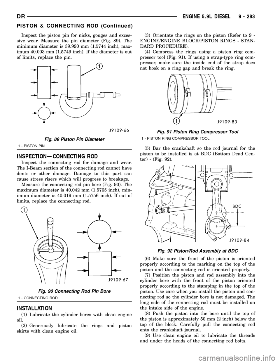
Inspect the piston pin for nicks, gouges and exces-
sive wear. Measure the pin diameter (Fig. 89). The
minimum diameter is 39.990 mm (1.5744 inch), max-
imum 40.003 mm (1.5749 inch). If the diameter is out
of limits, replace the pin.
INSPECTIONÐCONNECTING ROD
Inspect the connecting rod for damage and wear.
The I-Beam section of the connecting rod cannot have
dents or other damage. Damage to this part can
cause stress risers which will progress to breakage.
Measure the connecting rod pin bore (Fig. 90). The
maximum diameter is 40.042 mm (1.5765 inch), min-
imum diameter is 40.019 mm (1.5756 inch). If out of
limits, replace the connecting rod.
INSTALLATION
(1) Lubricate the cylinder bores with clean engine
oil.
(2) Generously lubricate the rings and piston
skirts with clean engine oil.(3) Orientate the rings on the piston (Refer to 9 -
ENGINE/ENGINE BLOCK/PISTON RINGS - STAN-
DARD PROCEDURE).
(4) Compress the rings using a piston ring com-
pressor tool (Fig. 91). If using a strap-type ring com-
pressor, make sure the inside end of the strap does
not hook on a ring gap and break the ring.
(5) Bar the crankshaft so the rod journal for the
piston to be installed is at BDC (Bottom Dead Cen-
ter) - (Fig. 92).
(6) Make sure the front of the piston is oriented
properly according to the marking on the top of the
piston and the connecting rod is oriented properly.
(7) Position the piston and rod assembly into the
cylinder bore with the front of the piston oriented
properly according to the stamping in the top of the
piston. Use care when you install the piston and con-
necting rod so the cylinder bore is not damaged. The
long side of the connecting rod must be installed on
the intake side of the engine.
(8) Push the piston into the bore until the top of
the piston is approximately 50 mm (2 inch) below the
top of the block. Carefully pull the connecting rod
onto the crankshaft journal.
(9) Use clean engine oil to lubricate the threads
and under the heads of the connecting rod bolts.
Fig. 89 Piston Pin Diameter
1 - PISTON PIN
Fig. 90 Connecting Rod Pin Bore
1 - CONNECTING ROD
Fig. 91 Piston Ring Compressor Tool
1 - PISTON RING COMPRESSOR TOOL
Fig. 92 Piston/Rod Assembly at BDC
DRENGINE 5.9L DIESEL 9 - 283
PISTON & CONNECTING ROD (Continued)
Page 1537 of 2627
(6) Full load boost pressure at rated speed will be
158 - 186 kPa (23 - 27 psi.) depending on engine hp
rating.. If pressure readings are are not within this
range inspect for the following:
²Restricted air inlet system
²Leak in the charge air cooler system (Refer to 11
- EXHAUST SYSTEM/TURBOCHARGER SYSTEM/
CHARGE AIR COOLER AND PLUMBING - DIAG-
NOSIS AND TESTING)
²Turbocharger wastegate broken or misadjusted
²Restricted/high pressure drop across charge air
cooler
²Turbocharger damaged (Refer to 11 - EXHAUST
SYSTEM/TURBOCHARGER SYSTEM/TURBO-
CHARGER - INSPECTION)
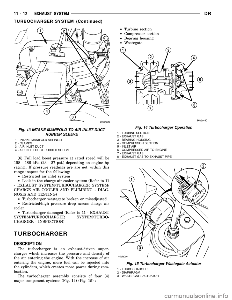
TURBOCHARGER
DESCRIPTION
The turbocharger is an exhaust-driven super-
charger which increases the pressure and density of
the air entering the engine. With the increase of air
entering the engine, more fuel can be injected into
the cylinders, which creates more power during com-
bustion.
The turbocharger assembly consists of four (4)
major component systems (Fig. 14) (Fig. 15) :²Turbine section
²Compressor section
²Bearing housing
²Wastegate
Fig. 13 INTAKE MANIFOLD TO AIR INLET DUCT
RUBBER SLEEVE
1 - INTAKE MANIFOLD AIR INLET
2 - CLAMPS
3 - AIR INLET DUCT
4 - AIR INLET DUCT RUBBER SLEEVE
Fig. 14 Turbocharger Operation
1 - TURBINE SECTION
2 - EXHAUST GAS
3 - BEARING HOUSING
4 - COMPRESSOR SECTION
5 - INLET AIR
6 - COMPRESSED AIR TO ENGINE
7 - EXHAUST GAS
8 - EXHAUST GAS TO EXHAUST PIPE
Fig. 15 Turbocharger Wastegate Actuator
1 - TURBOCHARGER
2 - DIAPHRAGM
3 - WASTE GATE ACTUATOR
11 - 12 EXHAUST SYSTEMDR
TURBOCHARGER SYSTEM (Continued)
Page 1538 of 2627
OPERATION
Exhaust gas pressure and energy drive the tur-
bine, which in turn drives a centrifugal compressor
that compresses the inlet air, and forces the air into
the engine through the charge air cooler and plumb-
ing. Since heat is a by-product of this compression,
the air must pass through a charge air cooler to cool
the incoming air and maintain power and efficiency.
Increasing air flow to the engine provides:
²Improved engine performance
²Lower exhaust smoke density
²Improved operating economy
²Altitude compensation
²Noise reduction.
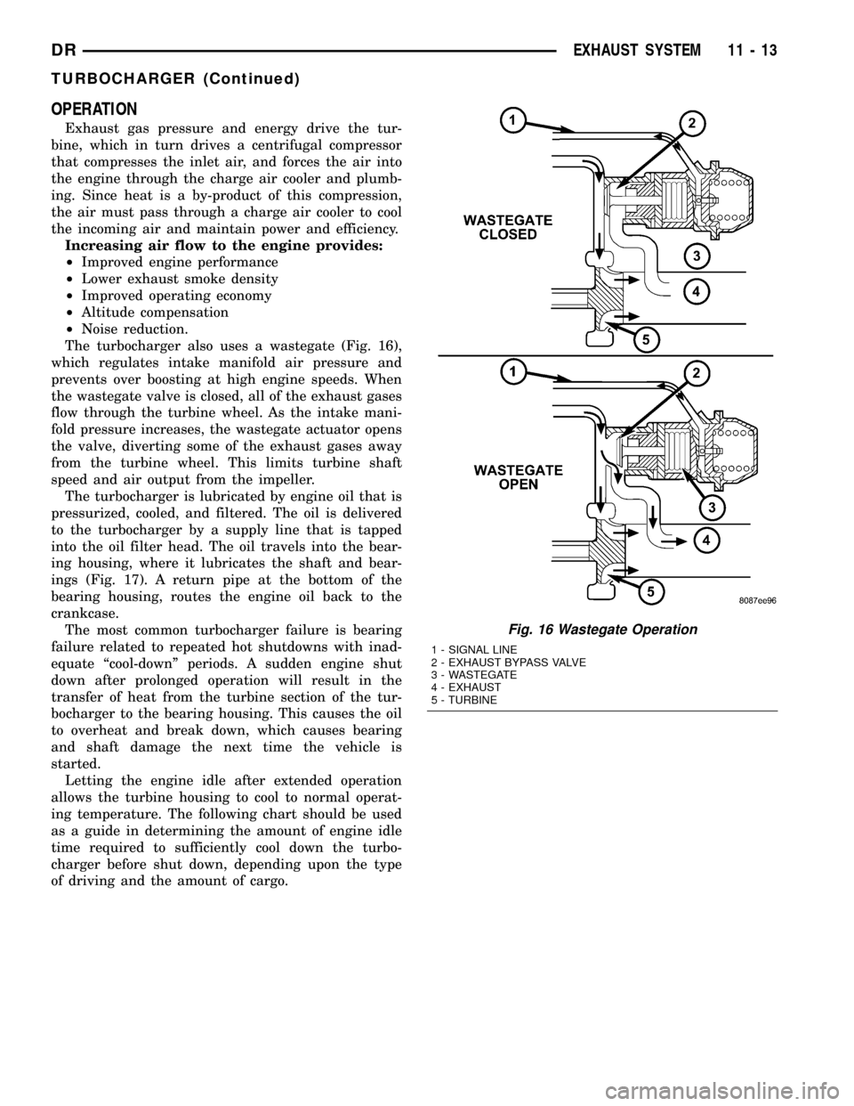
The turbocharger also uses a wastegate (Fig. 16),
which regulates intake manifold air pressure and
prevents over boosting at high engine speeds. When
the wastegate valve is closed, all of the exhaust gases
flow through the turbine wheel. As the intake mani-
fold pressure increases, the wastegate actuator opens
the valve, diverting some of the exhaust gases away
from the turbine wheel. This limits turbine shaft
speed and air output from the impeller.
The turbocharger is lubricated by engine oil that is
pressurized, cooled, and filtered. The oil is delivered
to the turbocharger by a supply line that is tapped
into the oil filter head. The oil travels into the bear-
ing housing, where it lubricates the shaft and bear-
ings (Fig. 17). A return pipe at the bottom of the
bearing housing, routes the engine oil back to the
crankcase.
The most common turbocharger failure is bearing
failure related to repeated hot shutdowns with inad-
equate ªcool-downº periods. A sudden engine shut
down after prolonged operation will result in the
transfer of heat from the turbine section of the tur-
bocharger to the bearing housing. This causes the oil
to overheat and break down, which causes bearing
and shaft damage the next time the vehicle is
started.
Letting the engine idle after extended operation
allows the turbine housing to cool to normal operat-
ing temperature. The following chart should be used
as a guide in determining the amount of engine idle
time required to sufficiently cool down the turbo-
charger before shut down, depending upon the type
of driving and the amount of cargo.
Fig. 16 Wastegate Operation
1 - SIGNAL LINE
2 - EXHAUST BYPASS VALVE
3 - WASTEGATE
4 - EXHAUST
5 - TURBINE
DREXHAUST SYSTEM 11 - 13
TURBOCHARGER (Continued)
Page 1544 of 2627
FRAMES & BUMPERS
TABLE OF CONTENTS
page page
BUMPERS
SPECIFICATIONS - TORQUE...............1
FRONT AIR DAM
REMOVAL.............................2
INSTALLATION..........................2
FRONT BUMPER
REMOVAL.............................2
INSTALLATION..........................2
FRONT FASCIA
REMOVAL.............................2
INSTALLATION..........................3
REAR BUMPER
REMOVAL.............................3
INSTALLATION..........................4
FRAME
WARNING
SAFETY PRECAUTIONS AND WARNINGS . . . 4
STANDARD PROCEDURE
STANDARD PROCEDURE - LIGHT DUTY
FRONT FRAME RAIL TIP REPLACEMENT....4
STANDARD PROCEDURE - HYDROFORM
FENDER RAIL REPAIR.................11
STANDARD PROCEDURE - REAR FRAME
H-SECTION REPLACEMENT.............13SPECIFICATIONS
SPECIFICATIONS - WELD PROCESS......15
SPECIFICATIONS - FRAME DIMENSIONS . . . 16
SPECIFICATIONS - TORQUE............22
FRONT CROSSMEMBER
REMOVAL.............................22
INSTALLATION.........................22
FRONT SKID PLATE
REMOVAL.............................23
INSTALLATION.........................23
FRONT TOW HOOK ASSEMBLY
REMOVAL.............................23
INSTALLATION.........................23
TRANSMISSION CROSSMEMBER
REMOVAL.............................24
INSTALLATION.........................24
TRAILER HITCH
REMOVAL.............................25
INSTALLATION.........................25
TRANSFER CASE SKID PLATE
REMOVAL.............................26
INSTALLATION.........................26
BUMPERS
SPECIFICATIONS - TORQUE
TORQUE SPECIFICATIONS
DESCRIPTION N´m Ft. Lbs. In. Lbs.
Front bumper center bracket nuts 95 70 Ð
Front bumper stud plate nuts 95 70 Ð
License plate hitch reinforcement bolts 54 40 Ð
Rear bumper support bracket stud plate nuts 54 40 Ð
Rear bumper support bracket to hitch bolts 54 40 Ð
Rear bumper to hitch bolts 54 40 Ð
DRFRAMES & BUMPERS 13 - 1