1998 DODGE RAM 1500 oil filter
[x] Cancel search: oil filterPage 1616 of 2627

STANDARD PROCEDURE
STANDARD PROCEDURES - WATER DRAINING
AT FUEL FILTER
Refer to Fuel Filter/Water Separator removal/in-
stallation for procedures.
STANDARD PROCEDURES - CLEANING FUEL
SYSTEM PARTS
CAUTION: Cleanliness cannot be overemphasized
when handling or replacing diesel fuel system com-
ponents. This especially includes the fuel injectors,
high-pressure fuel lines and fuel injection pump.
Very tight tolerances are used with these parts. Dirt
contamination could cause rapid part wear and pos-
sible plugging of fuel injector nozzle tip holes. This
in turn could lead to possible engine misfire.
Always wash/clean any fuel system component
thoroughly before disassembly and then air dry.
Cap or cover any open part after disassembly.
Before assembly, examine each part for dirt, grease
or other contaminants and clean if necessary. When
installing new parts, lubricate them with clean
engine oil or clean diesel fuel only.
STANDARD PROCEDURE - FUEL SYSTEM
PRIMING
A certain amount of air becomes trapped in the
fuel system when fuel system components on the
supply and/or high-pressure side are serviced or
replaced. Fuel system priming is accomplished using
the electric fuel transfer (lift) pump.
Servicing or replacing fuel system components will
not require fuel system priming.
The fuel transfer (lift) pump is self-priming: When
the key is first turned on (without cranking engine),
the pump operates for approximately 1 to 2 second
and then shuts off. The pump will also operate for up
to 25 seconds after the starter is quickly engaged,
and then disengaged without allowing the engine to
start. The pump shuts off immediately if the key is
on and the engine stops running.
(1) Turn key to CRANK position and quickly
release key to ON position before engine starts. This
will operate fuel transfer pump for approximately 25
seconds.
(2) Crank engine. If the engine does not start after
25 seconds, turn key OFF. Repeat previous step until
engine starts.
(3) Fuel system priming is now completed.
(4) Attempt to start engine. If engine will not
start, proceed to following steps.When engine does
start, it may run erratically and be noisy for a
few minutes. This is a normal condition.
CAUTION: Do not engage the starter motor for more
than 30 seconds at a time. Allow two minutes
between cranking intervals.
(5) Perform previous fuel priming procedure steps
using fuel transfer pump. Be sure fuel is present at
fuel tank.
(6) Crank the engine for 30 seconds at a time to
allow fuel system to prime.
WARNING: THE FUEL INJECTION PUMP SUPPLIES
EXTREMELY HIGH FUEL PRESSURE TO EACH INDI-
VIDUAL INJECTOR THROUGH THE HIGH-PRES-
SURE LINES. FUEL UNDER THIS AMOUNT OF
PRESSURE CAN PENETRATE THE SKIN AND
CAUSE PERSONAL INJURY. WEAR SAFETY GOG-
GLES AND ADEQUATE PROTECTIVE CLOTHING.
DO NOT LOOSEN FUEL FITTINGS WHILE ENGINE
IS RUNNING.
WARNING: ENGINE MAY START WHILE CRANKING
STARTER MOTOR.
Fig. 2 FUEL INJECTORS
1 - SOLENOID CONNECTIONS
2 - ROCKER HOUSING
3 - FUEL INJECTOR
4 - PASSTHROUGH CONNECTOR
DRFUEL DELIVERY - DIESEL 14 - 47
FUEL DELIVERY - DIESEL (Continued)
Page 1620 of 2627

(b) Install new o-ring to canister lid and lubri-
cate o-ring with clean engine oil.
(c) Position new element to canister lid. Place
this assembly into canister by rotating clockwise.
(d) Tighten cap to 34 N´m (25 ft. lbs.) torque. Do
not overtighten cap.
(3)Water-In-Fuel (WIF) Sensor:
(a) Install new o-ring seal to WIF sensor.
(b) Apply a light film of clean oil to o-ring seal.
(c) Install sensor into housing.
(d) Tighten sensor to 2.5 N´m (25 in. lbs.) torque.
(e) Connect electrical connector to WIF sensor.
(4)Fuel Heater Element:
(a) Install fuel heater into fuel filter housing.
(b) Install fuel heater thermostat into fuel filter
housing.
(c) Install fuel heater mounting screws and
tighten to 1-1.5 N´m (13 in. lbs.) torque.
(d) Connect electrical connector to fuel heater
thermostat.
(e) Install new filter cover O-ring onto fuel filter
housing cover and lubricate with clean engine oil.
(f) Tighten fuel filter housing cover (lid) to 34
N´m (25 ft. lbs.).
(5)Drain Valve:
(a) Install 2 new o-rings to valve and filter hous-
ing.
(b) Lubricate with silicon grease.
(c) Install fuel drain valve.
(d) Install 4 mounting screws and tighten to
1±1.5 N´m (8±13 in. lbs.) torque.
(e) Connect drain hose to drain valve.
(6) Start engine and check for leaks.
FUEL HEATER
DESCRIPTION
The fuel heater assembly is located on the side of
the fuel filter housing (Fig. 3).
The heater/element assembly is equipped with a
temperature sensor (thermostat) that senses fuel
temperature. This sensor is attached to the fuel heat-
er/element assembly.
OPERATION
The fuel heater is used to prevent diesel fuel from
waxing during cold weather operation.
When the temperature is below 45 8 degrees F,
the temperature sensor allows current to flow to the
heater element warming the fuel. When the temper-
ature is above 75 8 degrees F, the sensor stops cur-
rent flow to the heater element.
Battery voltage to operate the fuel heater element
is supplied from the ignition switch and through the
fuel heater relay. Also refer to Fuel Heater Relay.
Fig. 3 FILTER HOUSING
1 - FILTER HOUSING
2 - FUEL HEATER AND THERMOSTAT
3 - FUEL HEATER MOUNTING SCREWS
4 - FUEL HEATER ELEC. CONNECTOR
5 - WIF SENSOR
6 - WIF SENSOR ELEC. CONNECTOR
7 - DRAIN HOSE
8 - DRAIN VALVE MOUNTING SCREWS
9 - DRAIN VALVE
Fig. 4 FILTER COVER (LID)
1 - FILTER COVER
2 - ATTACH SOCKET HERE
DRFUEL DELIVERY - DIESEL 14 - 51
FUEL FILTER / WATER SEPARATOR (Continued)
Page 1623 of 2627

REMOVAL
CAUTION: Cleanliness cannot be overemphasized
when handling or replacing diesel fuel system com-
ponents. This especially includes the fuel injectors,
high-pressure fuel lines and fuel injection pump.
Very tight tolerances are used with these parts. Dirt
contamination could cause rapid part wear and pos-
sible plugging of fuel injector nozzle tip holes. This
in turn could lead to possible engine misfire.
Always wash/clean any fuel system component
thoroughly before disassembly and then air dry.
Cap or cover any open part after disassembly.
Before assembly, examine each part for dirt, grease
or other contaminants and clean if necessary. When
installing new parts, lubricate them with clean
engine oil or clean diesel fuel only.
(1) Disconnect both negative battery cables at both
batteries. Cover and isolate ends of both cables.
(2) Remove intake manifold air intake tube (above
injection pump) and its rubber connector hose (Fig.
7).
(3) Remove accessory drive belt.
(4) Thoroughly clean the rear of injection pump,
and attachment points for its 3 fuel lines (Fig. 8).
Also clean the opposite ends of these same 3 lines at
their attachment points.
(5) Disconnect Fuel Control Actuator (FCA) electri-
cal connector at rear of injection pump (Fig. 9).
CAUTION: Whenever a fuel line fitting is connected
to a secondary fitting, always use a back-up wrench
on the secondary fitting. Do not allow the second-
ary fitting to rotate.
(6) Remove fuel line (injection pump-to-fuel pres-
sure limiting valve).
(7) Remove fuel line (injection pump-to-fuel rail).
Use back-up wrench on fitting at fuel pump.
(8) Remove fuel line (injection pump-to-fuel filter
housing).
(9) Remove fuel pump drive gear access cover
(plate) with a 3/8º drive ratchet. Plate is threaded to
timing gear cover (Fig. 10).
(10) Remove fuel pump drive gear mounting nut
and washer.
(11) Attach C3428B, or L4407A (or equivalent)
gear puller (Fig. 11) to pump drive gear with 2 bolts,
and separate gear from pump (a keyway is not used
on this particular injection pump). Leave drive gear
hanging loose within timing gear cover.
(12) Remove 3 injection pump mounting nuts (Fig.
12), and remove pump from engine.
Fig. 7 INTAKE TUBE AND CONNECTING HOSE
1 - MANIFOLD ABOVE HEATERS
2 - RUBBER CONNECTING HOSE
3 - METAL INTAKE TUBE
4 - CLAMPS (2)
Fig. 8 OVERFLOW VALVE
1 - BANJO BOLTS
2 - PUMP MOUNTING NUTS (3)
3 - FUEL INJECTION PUMP
4 - CASCADE OVERFLOW VALVE
14 - 54 FUEL DELIVERY - DIESELDR
FUEL INJECTION PUMP (Continued)
Page 1625 of 2627

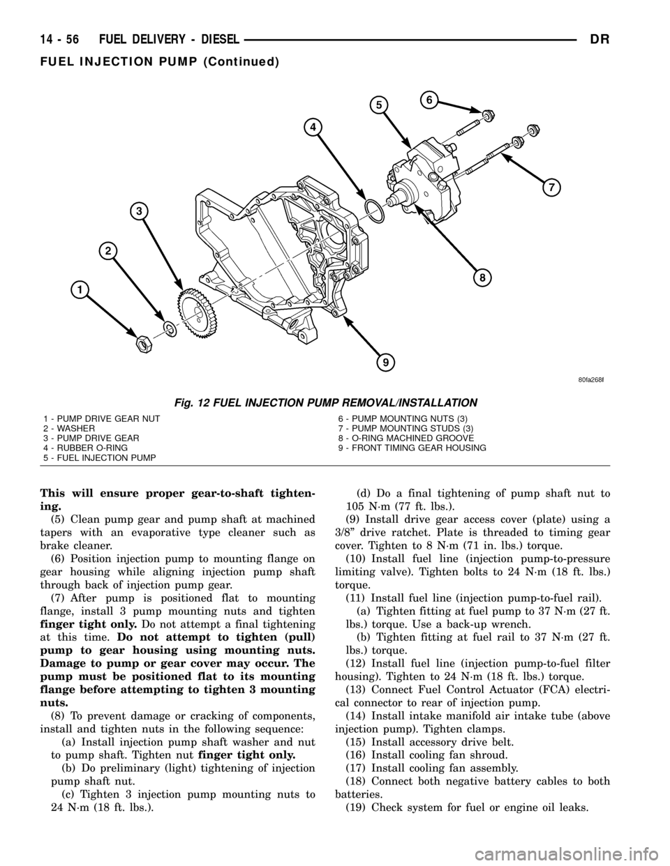
This will ensure proper gear-to-shaft tighten-
ing.
(5) Clean pump gear and pump shaft at machined
tapers with an evaporative type cleaner such as
brake cleaner.
(6) Position injection pump to mounting flange on
gear housing while aligning injection pump shaft
through back of injection pump gear.
(7) After pump is positioned flat to mounting
flange, install 3 pump mounting nuts and tighten
finger tight only.Do not attempt a final tightening
at this time.Do not attempt to tighten (pull)
pump to gear housing using mounting nuts.
Damage to pump or gear cover may occur. The
pump must be positioned flat to its mounting
flange before attempting to tighten 3 mounting
nuts.
(8) To prevent damage or cracking of components,
install and tighten nuts in the following sequence:
(a) Install injection pump shaft washer and nut
to pump shaft. Tighten nutfinger tight only.
(b) Do preliminary (light) tightening of injection
pump shaft nut.
(c) Tighten 3 injection pump mounting nuts to
24 N´m (18 ft. lbs.).(d) Do a final tightening of pump shaft nut to
105 N´m (77 ft. lbs.).
(9) Install drive gear access cover (plate) using a
3/8º drive ratchet. Plate is threaded to timing gear
cover. Tighten to 8 N´m (71 in. lbs.) torque.
(10) Install fuel line (injection pump-to-pressure
limiting valve). Tighten bolts to 24 N´m (18 ft. lbs.)
torque.
(11) Install fuel line (injection pump-to-fuel rail).
(a) Tighten fitting at fuel pump to 37 N´m (27 ft.
lbs.) torque. Use a back-up wrench.
(b) Tighten fitting at fuel rail to 37 N´m (27 ft.
lbs.) torque.
(12) Install fuel line (injection pump-to-fuel filter
housing). Tighten to 24 N´m (18 ft. lbs.) torque.
(13) Connect Fuel Control Actuator (FCA) electri-
cal connector to rear of injection pump.
(14) Install intake manifold air intake tube (above
injection pump). Tighten clamps.
(15) Install accessory drive belt.
(16) Install cooling fan shroud.
(17) Install cooling fan assembly.
(18) Connect both negative battery cables to both
batteries.
(19) Check system for fuel or engine oil leaks.
Fig. 12 FUEL INJECTION PUMP REMOVAL/INSTALLATION
1 - PUMP DRIVE GEAR NUT
2 - WASHER
3 - PUMP DRIVE GEAR
4 - RUBBER O-RING
5 - FUEL INJECTION PUMP6 - PUMP MOUNTING NUTS (3)
7 - PUMP MOUNTING STUDS (3)
8 - O-RING MACHINED GROOVE
9 - FRONT TIMING GEAR HOUSING
14 - 56 FUEL DELIVERY - DIESELDR
FUEL INJECTION PUMP (Continued)
Page 1649 of 2627

INTAKE AIR HEATER
DESCRIPTION
The intake manifold air heater element assembly
is located in the top of the intake manifold.
OPERATION
The air heater elements are used to heat incoming
air to the intake manifold. This is done to help
engine starting and improve driveability with cool or
cold outside temperatures.
Electrical supply for the 2 air heater elements is
controlled by the Engine Control Module (ECM)
through the 2 air heater relays. Refer to Intake Man-
ifold Air Heater Relays for more information.
Two heavy-duty cables connect the 2 air heater ele-
ments to the 2 air heater relays. Each of these cables
will supply approximately 95 amps at 12 volts to an
individual heating element within the heater block
assembly.
Refer to the Powertrain Diagnostic Procedures
manual for electrical operation and complete descrip-
tion of the intake heaters, including pre-heat and
post-heat cycles.
REMOVAL
If servicing either of the heater elements, the
entire block/element assembly must be replaced.
(1) Disconnect both negative battery cables at both
batteries. Cover and isolate ends of both cables.
(2) Remove both the intake manifold air intake
tube (above injection pump), and its rubber connector
hose (Fig. 26).
(3) Lift 2 rubber covers (Fig. 27) to gain access to 2
positive (+) cable nuts. Remove these 2 nuts (Fig. 28)
and remove 2 cables from studs.
(4) Disconnect ground strap (Fig. 27) at heater ele-
ment stud.
(5) Remove wiring harness clips.
(6) Remove engine oil dipstick tube bracket from
air inlet connection and fuel filter housing.
(7) Remove 4 housing mounting bolts (Fig. 27) and
remove heater element assembly.
INSTALLATION
If servicing either of the heater elements, the
entire block/element assembly must be replaced.
(1) Using 2 new gaskets, position element assem-
bly and air housing to intake manifold.
(2) Install ground cable to air housing.
(3) Install 4 housing bolts and tighten to 24 N´m
(18 ft. lbs.) torque.
(4) Connect 2 positive (+) heater cables at cable
mounting studs.Do not allow either of the cable
eyelets to contact any other metal source other
than the cable nuts/studs.
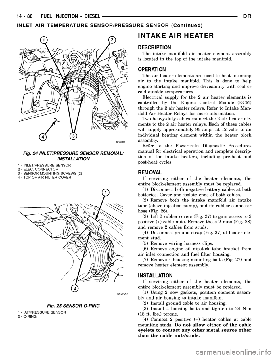
Fig. 24 INLET/PRESSURE SENSOR REMOVAL/
INSTALLATION
1 - INLET/PRESSURE SENSOR
2 - ELEC. CONNECTOR
3 - SENSOR MOUNTING SCREWS (2)
4 - TOP OF AIR FILTER COVER
Fig. 25 SENSOR O-RING
1 - IAT/PRESSURE SENSOR
2 - O-RING
14 - 80 FUEL INJECTION - DIESELDR
INLET AIR TEMPERATURE SENSOR/PRESSURE SENSOR (Continued)
Page 1833 of 2627

AUTOMATIC TRANSMISSION - 48RE
TABLE OF CONTENTS
page page
AUTOMATIC TRANSMISSION - 48RE
DESCRIPTION........................132
OPERATION..........................134
DIAGNOSIS AND TESTING
DIAGNOSIS AND TESTING - AUTOMATIC
TRANSMISSION.....................140
DIAGNOSIS AND TESTING - PRELIMINARY . 140
DIAGNOSIS AND TESTING - ROAD
TESTING...........................140
DIAGNOSIS AND TESTING - HYDRAULIC
PRESSURE TEST....................141
DIAGNOSIS AND TESTING - AIR TESTING
TRANSMISSION CLUTCH AND BAND
OPERATION........................144
DIAGNOSIS AND TESTING - CONVERTER
HOUSING FLUID LEAK................144
DIAGNOSIS AND TESTING - DIAGNOSIS
CHARTS...........................145
STANDARD PROCEDURE - ALUMINUM
THREAD REPAIR.....................158
REMOVAL............................158
DISASSEMBLY........................160
CLEANING...........................166
INSPECTION.........................166
ASSEMBLY...........................166
INSTALLATION........................174
SCHEMATICS AND DIAGRAMS
HYDRAULIC SCHEMATICS.............176
SPECIFICATIONS
TRANSMISSION.....................189
SPECIAL TOOLS
RE TRANSMISSION..................191
ACCUMULATOR
DESCRIPTION........................193
OPERATION..........................193
INSPECTION.........................194
BANDS
DESCRIPTION........................194
OPERATION..........................194
ADJUSTMENTS
ADJUSTMENT - BANDS...............195
BRAKE TRANSMISSION SHIFT INTERLOCK
SYSTEM
DESCRIPTION........................196
OPERATION..........................196
DIAGNOSIS AND TESTING - BRAKE
TRANSMISSION SHIFT INTERLOCK......196
ADJUSTMENTS - BRAKE TRANSMISSION
SHIFT INTERLOCK...................196ELECTRONIC GOVERNOR
DESCRIPTION........................197
OPERATION..........................198
REMOVAL............................199
INSTALLATION........................200
EXTENSION HOUSING SEAL
REMOVAL............................201
INSTALLATION........................201
FLUID AND FILTER
DIAGNOSIS AND TESTING
DIAGNOSIS AND TESTING - EFFECTS OF
INCORRECT FLUID LEVEL.............201
DIAGNOSIS AND TESTING - CAUSES OF
BURNT FLUID.......................201
DIAGNOSIS AND TESTING - FLUID
CONTAMINATION....................202
STANDARD PROCEDURE
STANDARD PROCEDURE - FLUID LEVEL
CHECK............................202
STANDARD PROCEDURE - FLUID AND
FILTER REPLACEMENT...............203
STANDARD PROCEDURE - TRANSMISSION
FILL...............................204
FRONT CLUTCH
DESCRIPTION........................205
OPERATION..........................205
DISASSEMBLY........................205
INSPECTION.........................206
ASSEMBLY...........................207
FRONT SERVO
DESCRIPTION........................208
OPERATION..........................208
DISASSEMBLY........................209
CLEANING...........................209
INSPECTION.........................209
ASSEMBLY...........................209
GEARSHIFT CABLE
DIAGNOSIS AND TESTING - GEARSHIFT
CABLE.............................210
REMOVAL............................210
INSTALLATION........................211
ADJUSTMENTS
GEARSHIFT CABLE..................212
OIL PUMP
DESCRIPTION........................213
OPERATION..........................213
DISASSEMBLY........................214
CLEANING...........................214
INSPECTION.........................214
ASSEMBLY...........................214
21 - 130 AUTOMATIC TRANSMISSION - 48REDR
Page 1846 of 2627

(3) Have helper start and run engine at 1600 rpm
for test.
(4)
Move transmission shift lever four detents rear-
ward from full forward position. This is Reverse range.
(5) Move transmission throttle lever fully forward
then fully rearward and note reading at Gauge
C-3293-SP.
(6) Pressure should be 145 - 175 psi (1000-1207
kPa) with throttle lever forward and increase to 230 -
280 psi (1586-1931 kPa) as lever is gradually moved
rearward.
Test Five - Governor Pressure
This test checks governor operation by measuring
governor pressure response to changes in vehicle
speed. It is usually not necessary to check governor
operation unless shift speeds are incorrect or if the
transmission will not downshift. The test should be
performed on the road or on a hoist that will allow
the rear wheels to rotate freely.
(1) Move 100 psi Test Gauge C-3292 to governor
pressure port.
(2) Move transmission shift lever two detents rear-
ward from full forward position. This is D range.
(3) Have helper start and run engine at curb idle
speed. Then firmly apply service brakes so wheels
will not rotate.
(4) Note governor pressure:
²
Governor pressure should be no more than 20.6
kPa (3 psi) at curb idle speed and wheels not rotating.
²If pressure exceeds 20.6 kPa (3 psi), a fault
exists in governor pressure control system.
(5) Release brakes, slowly increase engine speed,
and observe speedometer and pressure test gauge (do
not exceed 30 mph on speedometer). Governor pres-
sure should increase in proportion to vehicle speed.
Or approximately 6.89 kPa (1 psi) for every 1 mph.
(6) Governor pressure rise should be smooth and
drop back to no more than 20.6 kPa (3 psi), after
engine returns to curb idle and brakes are applied to
prevent wheels from rotating.
(7)
Compare results of pressure test with analysis
chart.
Test Six - Transmission In Overdrive Fourth Gear
This test checks line pressure at the overdrive
clutch in fourth gear range. Use 300 psi Test Gauge
C-3293-SP for this test. The test should be performed
on the road or on a chassis dyno.
(1)
Remove tachometer; it is not needed for this test.
(2) Move 300 psi Gauge to overdrive clutch pres-
sure test port. Then remove other gauge and reinstall
test port plug.
(3) Lower vehicle.
(4) Turn OD switch on.(5) Secure test gauge so it can be viewed from
drivers seat.
(6) Start engine and shift into D range.
(7) Increase vehicle speed gradually until 3-4 shift
occurs and note gauge pressure.
(8) Pressure should be 524-565 kPa (76-82 psi)
with closed throttle and increase to 690-896 kPa
(100-130 psi) at 1/2 to 3/4 throttle. Note that pres-
sure can increase to around 965 kPa (140 psi) at full
throttle.
(9) Return to shop or move vehicle off chassis
dyno.
PRESSURE TEST ANALYSIS CHART
TEST CONDITION INDICATION
Line pressure OK during
any one testPump and regulator
valve OK
Line pressure OK in R
but low in D, 2, 1Leakage in rear clutch
area (seal rings, clutch
seals)
Pressure low in D Fourth
Gear RangeOverdrive clutch piston
seal, or check ball
problem
Pressure OK in 1, 2 but
low in D3 and RLeakage in front clutch
area
Pressure OK in 2 but low
in R and 1Leakage in rear servo
Front servo pressure in 2 Leakage in servo; broken
servo ring or cracked
servo piston
Pressure low in all
positionsClogged filter, stuck
regulator valve, worn or
faulty pump, low oil level
Governor pressure too
high at idle speedGovernor pressure
solenoid valve system
fault. Refer to diagnostic
book.
Governor pressure low at
all mph figuresFaulty governor pressure
solenoid, transmission
control module, or
governor pressure
sensor
Lubrication pressure low
at all throttle positionsClogged fluid cooler or
lines, seal rings leaking,
worn pump bushings,
pump, clutch retainer, or
clogged filter.
Line pressure high Output shaft plugged,
sticky regulator valve
Line pressure low Sticky regulator valve,
clogged filter, worn pump
DRAUTOMATIC TRANSMISSION - 48RE 21 - 143
AUTOMATIC TRANSMISSION - 48RE (Continued)
Page 1850 of 2627

CONDITION POSSIBLE CAUSES CORRECTION
DELAYED ENGAGEMENT
(FROM NEUTRAL TO
DRIVE OR REVERSE)1. Fluid Level Low. 1. Correct level and check for leaks.
2. Filter Clogged. 2. Change filter.
3. Gearshift Linkage Mis-adjusted. 3. Adjust linkage and repair linkage if worn
or damaged.
4. Torque Converter Drain Back (Oil
drains from torque converter into
transmission sump).4. If vehicle moves normally after 5
seconds after shifting into gear, no repair is
necessary. If longer, inspect pump bushing
for wear. Replace pump house.
5. Rear Band Mis-adjusted. 5. Adjust band.
6. Valve Body Filter Plugged. 6. Replace fluid and filter. If oil pan and old
fluid were full of clutch disc material and/or
metal particles, overhaul will be necessary.
7. Oil Pump Gears Worn/Damaged. 7. Remove transmission and replace oil
pump.
8. Governor Circuit and Solenoid
Valve Electrical Fault.8. Test with DRBTscan tool and repair as
required.
9. Hydraulic Pressure Incorrect. 9. Perform pressure test, remove
transmission and repair as needed.
10. Reaction Shaft Seal Rings
Worn/Broken.10. Remove transmission, remove oil pump
and replace seal rings.
11. Rear Clutch/Input Shaft, Rear
Clutch Seal Rings Damaged.11. Remove and disassemble transmission
and repair as necessary.
12. Regulator Valve Stuck. 12. Clean.
13. Cooler Plugged. 13. Transfer case failure can plug cooler.
NO DRIVE RANGE
(REVERSE OK)1. Fluid Level Low. 1. Add fluid and check for leaks if drive is
restored.
2. Gearshift Linkage/Cable
Loose/Misadjusted.2. Repair or replace linkage components.
3. Rear Clutch Burnt. 3. Remove and disassemble transmission
and rear clutch and seals. Repair/replace
worn or damaged parts as needed.
4. Valve Body Malfunction. 4. Remove and disassemble valve body.
Replace assembly if any valves or bores
are damaged.
5. Transmission Overrunning Clutch
Broken.5. Remove and disassemble transmission.
Replace overrunning clutch.
6. Input Shaft Seal Rings Worn/
Damaged.6. Remove and disassemble transmission.
Replace seal rings and any other worn or
damaged parts.
7. Front Planetary Failed Broken. 7. Remove and repair.
DRAUTOMATIC TRANSMISSION - 48RE 21 - 147
AUTOMATIC TRANSMISSION - 48RE (Continued)