1998 DODGE RAM 1500 Cooling system
[x] Cancel search: Cooling systemPage 1383 of 2627
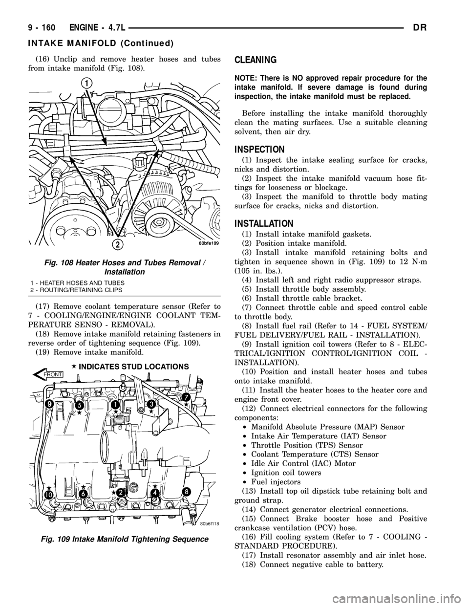
(16) Unclip and remove heater hoses and tubes
from intake manifold (Fig. 108).
(17) Remove coolant temperature sensor (Refer to
7 - COOLING/ENGINE/ENGINE COOLANT TEM-
PERATURE SENSO - REMOVAL).
(18) Remove intake manifold retaining fasteners in
reverse order of tightening sequence (Fig. 109).
(19) Remove intake manifold.CLEANING
NOTE: There is NO approved repair procedure for the
intake manifold. If severe damage is found during
inspection, the intake manifold must be replaced.
Before installing the intake manifold thoroughly
clean the mating surfaces. Use a suitable cleaning
solvent, then air dry.
INSPECTION
(1) Inspect the intake sealing surface for cracks,
nicks and distortion.
(2) Inspect the intake manifold vacuum hose fit-
tings for looseness or blockage.
(3) Inspect the manifold to throttle body mating
surface for cracks, nicks and distortion.
INSTALLATION
(1) Install intake manifold gaskets.
(2) Position intake manifold.
(3) Install intake manifold retaining bolts and
tighten in sequence shown in (Fig. 109) to 12 N´m
(105 in. lbs.).
(4) Install left and right radio suppressor straps.
(5) Install throttle body assembly.
(6) Install throttle cable bracket.
(7) Connect throttle cable and speed control cable
to throttle body.
(8) Install fuel rail (Refer to 14 - FUEL SYSTEM/
FUEL DELIVERY/FUEL RAIL - INSTALLATION).
(9) Install ignition coil towers (Refer to 8 - ELEC-
TRICAL/IGNITION CONTROL/IGNITION COIL -
INSTALLATION).
(10) Position and install heater hoses and tubes
onto intake manifold.
(11) Install the heater hoses to the heater core and
engine front cover.
(12) Connect electrical connectors for the following
components:
²Manifold Absolute Pressure (MAP) Sensor
²Intake Air Temperature (IAT) Sensor
²Throttle Position (TPS) Sensor
²Coolant Temperature (CTS) Sensor
²Idle Air Control (IAC) Motor
²Ignition coil towers
²Fuel injectors
(13) Install top oil dipstick tube retaining bolt and
ground strap.
(14) Connect generator electrical connections.
(15) Connect Brake booster hose and Positive
crankcase ventilation (PCV) hose.
(16) Fill cooling system (Refer to 7 - COOLING -
STANDARD PROCEDURE).
(17) Install resonator assembly and air inlet hose.
(18) Connect negative cable to battery.
Fig. 108 Heater Hoses and Tubes Removal /
Installation
1 - HEATER HOSES AND TUBES
2 - ROUTING/RETAINING CLIPS
Fig. 109 Intake Manifold Tightening Sequence
9 - 160 ENGINE - 4.7LDR
INTAKE MANIFOLD (Continued)
Page 1387 of 2627
INSTALLATION
RIGHT EXHAUST MANIFOLD
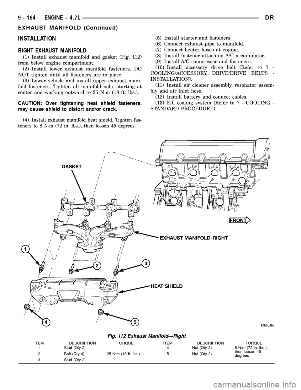
(1) Install exhaust manifold and gasket (Fig. 112)
from below engine compartment.
(2) Install lower exhaust manifold fasteners. DO
NOT tighten until all fasteners are in place.
(3) Lower vehicle and install upper exhaust mani-
fold fasteners. Tighten all manifold bolts starting at
center and working outward to 25 N´m (18 ft. lbs.).
CAUTION: Over tightening heat shield fasteners,
may cause shield to distort and/or crack.
(4)
Install exhaust manifold heat shield. Tighten fas-
teners to 8 N´m (72 in. lbs.), then loosen 45 degrees.
(5) Install starter and fasteners.
(6) Connect exhaust pipe to manifold.
(7) Connect heater hoses at engine.
(8) Install fastener attaching A/C accumulator.
(9) Install A/C compressor and fasteners.
(10) Install accessory drive belt (Refer to 7 -
COOLING/ACCESSORY DRIVE/DRIVE BELTS -
INSTALLATION).
(11) Install air cleaner assembly, resonator assem-
bly and air inlet hose.
(12) Install battery and connect cables.
(13) Fill cooling system (Refer to 7 - COOLING -
STANDARD PROCEDURE).
Fig. 112 Exhaust ManifoldÐRight
ITEM DESCRIPTION TORQUE ITEM DESCRIPTION TORQUE
1 Stud (Qty 2)
25 N´m (18 ft. lbs.)4 Nut (Qty 2) 8 N´m (72 in. lbs.),
then loosen 45
degrees 2 Bolt (Qty 4) 5 Nut (Qty 2)
3 Stud (Qty 2)
9 - 164 ENGINE - 4.7LDR
EXHAUST MANIFOLD (Continued)
Page 1393 of 2627
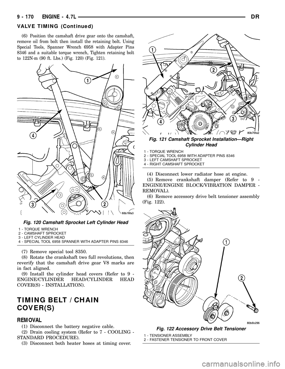
(6)Position the camshaft drive gear onto the camshaft,
remove oil from bolt then install the retaining bolt. Using
Special Tools, Spanner Wrench 6958 with Adapter Pins
8346 and a suitable torque wrench, Tighten retaining bolt
to 122N´m (90 ft. Lbs.) (Fig. 120) (Fig. 121).
(7) Remove special tool 8350.
(8) Rotate the crankshaft two full revolutions, then
reverify that the camshaft drive gear V8 marks are
in fact aligned.
(9) Install the cylinder head covers (Refer to 9 -
ENGINE/CYLINDER HEAD/CYLINDER HEAD
COVER(S) - INSTALLATION).
TIMING BELT / CHAIN
COVER(S)
REMOVAL
(1) Disconnect the battery negative cable.
(2) Drain cooling system (Refer to 7 - COOLING -
STANDARD PROCEDURE).
(3) Disconnect both heater hoses at timing cover.(4) Disconnect lower radiator hose at engine.
(5) Remove crankshaft damper (Refer to 9 -
ENGINE/ENGINE BLOCK/VIBRATION DAMPER -
REMOVAL).
(6) Remove accessory drive belt tensioner assembly
(Fig. 122).
Fig. 120 Camshaft Sprocket Left Cylinder Head
1 - TORQUE WRENCH
2 - CAMSHAFT SPROCKET
3 - LEFT CYLINDER HEAD
4 - SPECIAL TOOL 6958 SPANNER WITH ADAPTER PINS 8346
Fig. 121 Camshaft Sprocket InstallationÐRight
Cylinder Head
1 - TORQUE WRENCH
2 - SPECIAL TOOL 6958 WITH ADAPTER PINS 8346
3 - LEFT CAMSHAFT SPROCKET
4 - RIGHT CAMSHAFT SPROCKET
Fig. 122 Accessory Drive Belt Tensioner
1 - TENSIONER ASSEMBLY
2 - FASTENER TENSIONER TO FRONT COVER
9 - 170 ENGINE - 4.7LDR
VALVE TIMING (Continued)
Page 1395 of 2627
(8) Install lower radiator hose.
(9) Install both heater hoses.
(10) Fill cooling system (Refer to 7 - COOLING -
STANDARD PROCEDURE).
(11) Connect the battery negative cable.
TIMING BELT/CHAIN AND
SPROCKETS
REMOVAL
(1) Disconnect negative cable from battery.
(2) Drain cooling system (Refer to 7 - COOLING -
STANDARD PROCEDURE).
(3) Remove right and left cylinder head covers
(Refer to 9 - ENGINE/CYLINDER HEAD/CYLIN-
DER HEAD COVER(S) - REMOVAL).
(4) Remove radiator fan shroud.
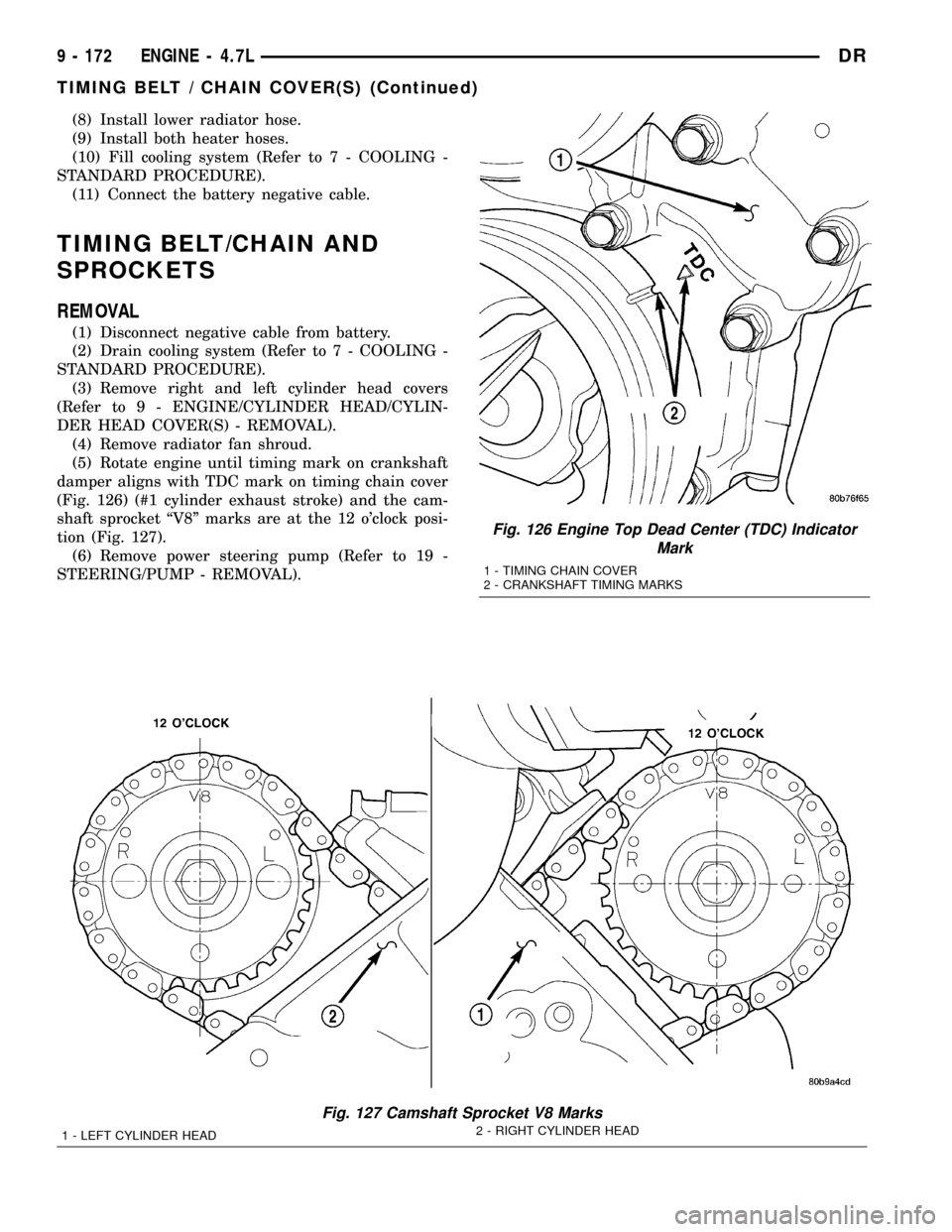
(5) Rotate engine until timing mark on crankshaft
damper aligns with TDC mark on timing chain cover
(Fig. 126) (#1 cylinder exhaust stroke) and the cam-
shaft sprocket ªV8º marks are at the 12 o'clock posi-
tion (Fig. 127).
(6) Remove power steering pump (Refer to 19 -
STEERING/PUMP - REMOVAL).
Fig. 126 Engine Top Dead Center (TDC) Indicator
Mark
1 - TIMING CHAIN COVER
2 - CRANKSHAFT TIMING MARKS
Fig. 127 Camshaft Sprocket V8 Marks
1 - LEFT CYLINDER HEAD2 - RIGHT CYLINDER HEAD
9 - 172 ENGINE - 4.7LDR
TIMING BELT / CHAIN COVER(S) (Continued)
Page 1401 of 2627
(19) Rotate engine two full revolutions. Verify tim-
ing marks are at the follow locations:
²primary chain idler sprocket dot is at 12 o'clock
(Fig. 133)
²primary chain crankshaft sprocket dot is at 6
o'clock (Fig. 133)
²secondary chain camshaft sprockets ªV8º marks
are at 12 o'clock (Fig. 133)
(20) Lubricate all three chains with engine oil.
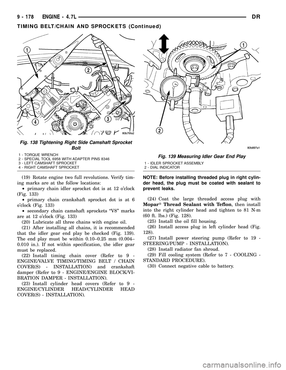
(21) After installing all chains, it is recommended
that the idler gear end play be checked (Fig. 139).
The end play must be within 0.10±0.25 mm (0.004±
0.010 in.). If not within specification, the idler gear
must be replaced.
(22) Install timing chain cover (Refer to 9 -
ENGINE/VALVE TIMING/TIMING BELT / CHAIN
COVER(S) - INSTALLATION) and crankshaft
damper (Refer to 9 - ENGINE/ENGINE BLOCK/VI-
BRATION DAMPER - INSTALLATION).
(23) Install cylinder head covers (Refer to 9 -
ENGINE/CYLINDER HEAD/CYLINDER HEAD
COVER(S) - INSTALLATION).NOTE: Before installing threaded plug in right cylin-
der head, the plug must be coated with sealant to
prevent leaks.
(24) Coat the large threaded access plug with
MopartThread Sealant with Teflon, then install
into the right cylinder head and tighten to 81 N´m
(60 ft. lbs.) (Fig. 128).
(25) Install the oil fill housing.
(26) Install access plug in left cylinder head (Fig.
128).
(27) Install power steering pump (Refer to 19 -
STEERING/PUMP - INSTALLATION).
(28) Install radiator fan shroud.
(29) Fill cooling system (Refer to 7 - COOLING -
STANDARD PROCEDURE).
(30) Connect negative cable to battery.
Fig. 138 Tightening Right Side Camshaft Sprocket
Bolt
1 - TORQUE WRENCH
2 - SPECIAL TOOL 6958 WITH ADAPTER PINS 8346
3 - LEFT CAMSHAFT SPROCKET
4 - RIGHT CAMSHAFT SPROCKETFig. 139 Measuring Idler Gear End Play
1 - IDLER SPROCKET ASSEMBLY
2 - DIAL INDICATOR
9 - 178 ENGINE - 4.7LDR
TIMING BELT/CHAIN AND SPROCKETS (Continued)
Page 1413 of 2627
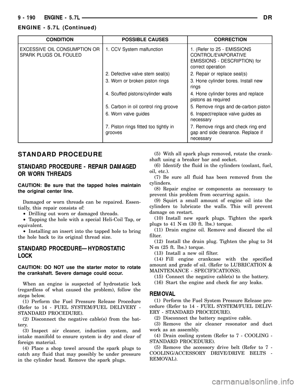
CONDITION POSSIBLE CAUSES CORRECTION
EXCESSIVE OIL CONSUMPTION OR
SPARK PLUGS OIL FOULED1. CCV System malfunction 1. (Refer to 25 - EMISSIONS
CONTROL/EVAPORATIVE
EMISSIONS - DESCRIPTION) for
correct operation
2. Defective valve stem seal(s) 2. Repair or replace seal(s)
3. Worn or broken piston rings 3. Hone cylinder bores. Install new
rings
4. Scuffed pistons/cylinder walls 4. Hone cylinder bores and replace
pistons as required
5. Carbon in oil control ring groove 5. Remove rings and de-carbon piston
6. Worn valve guides 6. Inspect/replace valve guides as
necessary
7. Piston rings fitted too tightly in
grooves7. Remove rings and check ring end
gap and side clearance. Replace if
necessary
STANDARD PROCEDURE
STANDARD PROCEDURE - REPAIR DAMAGED
OR WORN THREADS
CAUTION: Be sure that the tapped holes maintain
the original center line.
Damaged or worn threads can be repaired. Essen-
tially, this repair consists of:
²Drilling out worn or damaged threads.
²Tapping the hole with a special Heli-Coil Tap, or
equivalent.
²Installing an insert into the tapped hole to bring
the hole back to its original thread size.
STANDARD PROCEDUREÐHYDROSTATIC
LOCK
CAUTION: DO NOT use the starter motor to rotate
the crankshaft. Severe damage could occur.
When an engine is suspected of hydrostatic lock
(regardless of what caused the problem), follow the
steps below.
(1) Perform the Fuel Pressure Release Procedure
(Refer to 14 - FUEL SYSTEM/FUEL DELIVERY -
STANDARD PROCEDURE).
(2) Disconnect the negative cable(s) from the bat-
tery.
(3) Inspect air cleaner, induction system, and
intake manifold to ensure system is dry and clear of
foreign material.
(4) Place a shop towel around the spark plugs to
catch any fluid that may possibly be under pressure
in the cylinder head. Remove the spark plugs.(5) With all spark plugs removed, rotate the crank-
shaft using a breaker bar and socket.
(6) Identify the fluid in the cylinders (coolant, fuel,
oil, etc.).
(7) Be sure all fluid has been removed from the
cylinders.
(8) Repair engine or components as necessary to
prevent this problem from occurring again.
(9) Squirt a small amount of engine oil into the
cylinders to lubricate the walls. This will prevent
damage on restart.
(10) Install new spark plugs. Tighten the spark
plugs to 41 N´m (30 ft. lbs.) torque.
(11) Drain engine oil. Remove and discard the oil
filter.
(12) Install the drain plug. Tighten the plug to 34
N´m (25 ft. lbs.) torque.
(13) Install a new oil filter.
(14) Fill engine crankcase with the specified
amount and grade of oil. (Refer to LUBRICATION &
MAINTENANCE - SPECIFICATIONS).
(15) Connect the negative cable(s) to the battery.
(16) Start the engine and check for any leaks.
REMOVAL
(1) Perform the Fuel System Pressure Release pro-
cedure (Refer to 14 - FUEL SYSTEM/FUEL DELIV-
ERY - STANDARD PROCEDURE).
(2) Disconnect the battery negative cable.
(3) Remove the air cleaner resonator and duct
work as an assembly.
(4) Drain cooling system (Refer to 7 - COOLING -
STANDARD PROCEDURE).
(5) Remove the accessory drive belt (Refer to 7 -
COOLING/ACCESSORY DRIVE/DRIVE BELTS -
REMOVAL).
9 - 190 ENGINE - 5.7LDR
ENGINE - 5.7L (Continued)
Page 1414 of 2627
(6) Remove the viscous fan/drive (Refer to 7 -
COOLING/ENGINE/RADIATOR FAN - REMOVAL).
(7) Remove radiator (Refer to 7 - COOLING/EN-
GINE/RADIATOR - REMOVAL).
(8) Remove the upper crossmember and top core
support.
NOTE: It is not necessary to drain A/C system for
engine removal.
(9) Remove the A/C compressor with the lines
attached. Secure compressor out of the way.
(10) Remove generator assembly (Refer to 8 -
ELECTRICAL/CHARGING/GENERATOR -
REMOVAL).
(11) Remove the intake manifold and IAFM as an
assembly(Refer to 9 - ENGINE/MANIFOLDS/IN-
TAKE MANIFOLD - REMOVAL).
(12) Disconnect the heater hoses.
NOTE: It is not necessary to disconnect P/S hoses
from pump, for P/S pump removal.
(13) Remove the power steering pump and set
aside.
(14) Disconnect the fuel supply line (Refer to 14 -
FUEL SYSTEM/FUEL DELIVERY/QUICK CON-
NECT FITTING - STANDARD PROCEDURE).
(15) Raise and support the vehicle on a hoist and
drain the engine oil.
(16) Remove engine front mount thru-bolt nuts.
(17) Remove right side axle retaining bolts.
(18) Disconnect the transmission oil cooler lines
from their retainers at the oil pan bolts.
(19) Disconnect exhaust pipe at manifolds.
(20) Disconnect the starter wires. Remove starter
motor (Refer to 8 - ELECTRICAL/STARTING/
STARTER MOTOR - REMOVAL).
(21) Remove the structural dust cover and trans-
mission inspection cover,(Refer to 9 - ENGINE/EN-
GINE BLOCK/STRUCTURAL COVER - REMOVAL).
(22) Remove drive plate to converter bolts (Auto-
matic transmission equipped vehicles).
(23) Remove transmission bell housing to engine
block bolts.
(24) Lower the vehicle.
(25) Install engine lift fixture, special tool # 8984.
(26) Separate engine from transmission, remove
engine from vehicle, and install engine assembly on a
repair stand.
INSTALLATION
(1) Install engine lift fixture Special tool # 8984.
(2) Position the engine in the engine compartment.
(3) Lower engine into compartment and align
engine with transmission:²Manual Transmission: Align clutch disc assem-
bly (if disturbed). Install transmission input shaft
into clutch disc while mating engine and transmis-
sion surfaces. Install two transmission to engine
block mounting bolts finger tight.
²Automatic Transmission: Mate engine and trans-
mission and install two transmission to engine block
mounting bolts finger tight.
(4) Position the thru-bolt into the support cushion
brackets.
(5) Lower engine assembly until engine mount
through bolts rest in mount perches.
(6) Install remaining transmission to engine block
mounting bolts and tighten.
(7) Tighten engine mount through bolts.
(8) Install drive plate to torque converter bolts.
(Automatic transmission models)
(9) Install the structural dust cover and transmis-
sion dust cover,(Refer to 9 - ENGINE/ENGINE
BLOCK/STRUCTURAL COVER - INSTALLATION).
(10) Install the starter and connect the starter
wires (Refer to 8 - ELECTRICAL/STARTING/
STARTER MOTOR - INSTALLATION).
(11) Install exhaust pipe to manifold.
(12) Lower the vehicle.
(13) Remove engine lift fixture, special tool # 8984.
(14) Connect the fuel supply line (Refer to 14 -
FUEL SYSTEM/FUEL DELIVERY/QUICK CON-
NECT FITTING - STANDARD PROCEDURE).
(15) Reinstall the power steering pump.
(16) Connect the heater hoses.
(17) Install the intake manifold.
(18) Using a new gasket, install throttle body
(Refer to 14 - FUEL SYSTEM/FUEL INJECTION/
THROTTLE BODY - INSTALLATION).
(19) Install the generator and wire connections
(Refer to 8 - ELECTRICAL/CHARGING/GENERA-
TOR - INSTALLATION).
(20) Install a/c compressor and lines (Refer to 24 -
HEATING & AIR CONDITIONING/PLUMBING/A/C
COMPRESSOR - INSTALLATION).
(21) Install the accessory drive belt (Refer to 7 -
COOLING/ACCESSORY DRIVE/DRIVE BELTS -
INSTALLATION).
(22) Install upper radiator support crossmember.
(23) Install radiator (Refer to 7 - COOLING/EN-
GINE/RADIATOR - INSTALLATION).
(24) Connect the radiator lower hose.
(25) Connect the transmission oil cooler lines to
the radiator.
(26) Install the fan shroud.
(27) Install the fan (Refer to 7 - COOLING/EN-
GINE/RADIATOR FAN - INSTALLATION).
(28) Connect the radiator upper hose.
(29) Install the washer bottle.
(30) Connect the transmission cooler lines.
DRENGINE - 5.7L 9 - 191
ENGINE - 5.7L (Continued)
Page 1415 of 2627
(31)Install the air cleaner resonator and duct work..
(32) Add engine oil to crankcase (Refer to LUBRI-
CATION & MAINTENANCE/FLUID TYPES - SPEC-
IFICATIONS).
(33) Fill cooling system (Refer to 7 - COOLING -
STANDARD PROCEDURE).
(34) Connect battery negative cable.
(35) Start engine and inspect for leaks.
(36) Road test vehicle.
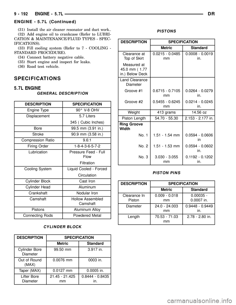
SPECIFICATIONS
5.7L ENGINE
GENERAL DESCRIPTION
DESCRIPTION SPECIFICATION
Engine Type 90É V-8 OHV
Displacement 5.7 Liters
345 ( Cubic Inches)
Bore 99.5 mm (3.91 in.)
Stroke 90.9 mm (3.58 in.)
Compression Ratio 9.6:1
Firing Order 1-8-4-3-6-5-7-2
Lubrication Pressure Feed - Full
Flow
Filtration
Cooling System Liquid Cooled - Forced
Circulation
Cylinder Block Cast Iron
Cylinder Head Aluminum
Crankshaft Nodular Iron
Camshaft Hollow Assembled
Camshaft
Pistons Aluminum Alloy
Connecting Rods Powdered Metal
CYLINDER BLOCK
DESCRIPTION SPECIFICATION
Metric Standard
Cylinder Bore
Diameter99.50 mm 3.917 in.
Out of Round
(MAX)0.0076 mm 0003 in.
Taper (MAX) 0.0127 mm 0.0005 in.
Lifter Bore
Diameter21.45 - 21.425
mm0.8444 - 0.8435
in.
PISTONS
DESCRIPTION SPECIFICATION
Metric Standard
Clearance at
Top of Skirt0.0215 - 0.0485
mm0.0008 - 0.0019
in.
Measured at
45.0 mm ( 1.77
in.) Below Deck
Land Clearance
Diameter
Groove #1 0.6715 - 0.7105
mm0.0264 - 0.0279
in.
Groove #2 0.5455 - 0.6245
mm0.0214 - 0.0245
in.
Weight 413 grams 14.56 oz
Piston Length 54.70 - 55.30 2.153 - 2.177 in.
Ring Groove
Width
No. 1 1.51 - 1.54 mm 0.0594 - 0.0606
in
No. 2 1.51 - 1.53 mm 0.0594 - 0.0602
in.
No. 3 3.030 - 3.055
mm0.1192 - 0.1202
in.
PISTON PINS
DESCRIPTION SPECIFICATION
Metric Standard
Clearance In
Piston0.009 - 0.018
mm0.00035 -
0.0007 in.
Diameter 24.0 - 24.003
mm0.9448 - 0.9449
in.
Length 70.53 - 71.03
mm2.78 - 2.80 in.
9 - 192 ENGINE - 5.7LDR
ENGINE - 5.7L (Continued)