1998 DODGE RAM 1500 table of contents
[x] Cancel search: table of contentsPage 2323 of 2627

DOORS - REAR
TABLE OF CONTENTS
page page
DOOR
REMOVAL.............................28
INSTALLATION.........................28
ADJUSTMENTS
ADJUSTMENT........................28
DOOR GLASS
REMOVAL.............................30
INSTALLATION.........................30
EXTERIOR HANDLE
REMOVAL.............................30
INSTALLATION.........................30
GLASS RUN CHANNEL
REMOVAL.............................30
INSTALLATION.........................31
HINGE
REMOVAL.............................31
INSTALLATION.........................31
INSIDE HANDLE ACTUATOR
REMOVAL.............................31
INSTALLATION.........................32
LATCH
REMOVAL.............................32INSTALLATION.........................32
ADJUSTMENTS
ADJUSTMENT........................33
LATCH STRIKER
REMOVAL.............................33
INSTALLATION.........................33
ADJUSTMENTS
ADJUSTMENT........................33
TRIM PANEL
REMOVAL.............................33
INSTALLATION.........................33
WATERDAM
REMOVAL.............................34
INSTALLATION.........................34
WINDOW REGULATOR - POWER
REMOVAL.............................34
INSTALLATION.........................34
WINDOW REGULATOR - MANUAL
REMOVAL.............................35
INSTALLATION.........................35
DOOR
REMOVAL
(1) Disconnect the door wire harness electrical con-
nector at the b-pillar. (Fig. 1)
(2) Using a grease pencil or equivalent, mark the
outline of the door hinges on the door to aid in instal-
lation.
(3) Support the door with a suitable lifting device.
NOTE: The epoxy bonded washers should not be
seperated from the hinge. If the washers are
removed the door may have to be re-adjusted.
(4) Remove the nuts and bolts attaching the door
hinges to the door.
INSTALLATION
(1) Support the door with a suitable lifting device
and install the door onto the hinges.
(2) Install the bolts, nuts and washers, if there
were removed previously, and tighten to 28 N´m (21
ft. lbs.).
(3) Connect the electrical connector.(4) Adjust the door as necessary. (Refer to 23 -
BODY/DOORS - REAR/DOOR - ADJUSTMENTS)
ADJUSTMENTS
ADJUSTMENT
NOTE: For vehicles equipped with four doors, it is
recommended that you adjust the rear door before
adjusting the front door.
²Door adjustment measurements should be
taken from stationary or welded body panels like
the roof, rocker or quarter panels.
²During adjustment procedures, it is recom-
mended that all the hinge fasteners be loosened
except for the upper most fasteners. Adjustments
can be made using the upper fasteners to hold the
door with final torque of the fasteners occurring
after correct door positioning is achieved.
23 - 28 DOORS - REARDR
Page 2331 of 2627

EXTERIOR
TABLE OF CONTENTS
page page
BODY SIDE MOLDINGS
REMOVAL.............................36
INSTALLATION.........................36
BODY ISOLATORS
REMOVAL.............................36
INSTALLATION.........................37
CARGO BOX
REMOVAL.............................37
INSTALLATION.........................37
CARGO BOX - TIE DOWN
REMOVAL.............................38
INSTALLATION.........................38
COWL GRILLE
REMOVAL.............................38
INSTALLATION.........................38
EXTERIOR NAME PLATES
REMOVAL.............................38
INSTALLATION.........................38
FRONT FENDER
REMOVAL.............................39
INSTALLATION.........................39
FUEL FILL DOOR
REMOVAL.............................39
INSTALLATION.........................39GRILLE
REMOVAL.............................40
INSTALLATION.........................40
GRILLE FRAME
REMOVAL.............................40
INSTALLATION.........................40
FRONT WHEELHOUSE SPLASH SHIELD
REMOVAL.............................41
INSTALLATION.........................41
REAR WHEELHOUSE SPLASH SHIELD
REMOVAL.............................41
INSTALLATION.........................41
SIDE VIEW MIRROR
REMOVAL.............................41
INSTALLATION.........................42
UPPER RADIATOR CROSSMEMBER
REMOVAL.............................42
INSTALLATION.........................42
SIDE VIEW MIRROR GLASS
REMOVAL.............................42
INSTALLATION.........................43
REAR FENDER
REMOVAL.............................44
INSTALLATION.........................44
BODY SIDE MOLDINGS
REMOVAL
NOTE: Body side moldings are attached to the body
panels with adhesive tape.
(1) Apply a length of masking tape on the body
panel, parallel to the top edge of the molding and to
one end to use as a guide for installation, if neces-
sary.
(2) If temperature is below 21ÉC (70ÉF) warm
molding with a heat lamp or gun. Do not exceed 52ÉC
(120ÉF) when heating molding.
(3) Using a trim stick C-4755 or equivalent,
remove and discard the molding from the outside of
the body panel.
INSTALLATION
(1) Thoroughly clean all residue from the body side
molding attachment area of the body panel.(2) Wipe area with a clean lint free cloth moist-
ened with a 50% solution of water and alcohol and
wipe dry immediately with a dry lint free cloth.
(3) Apply new body side molding using the guide
tape on the body panel and apply consistent and uni-
form pressure of approximately 40 p.s.i. over the
entire surface of the molding.
BODY ISOLATORS
REMOVAL
(1) Loosen all cab to frame mounting bolts (six
standard cab, eight quad cab). (Fig. 1)
(2) Remove the mounting bolts and rebound cush-
ions
(3) Using a floor jack and block of wood under the
cab sill, lift the body to gain access to the isolators.
(4) Remove the isolators.
(5) Install new isolators and repeat steps one
through 4, for the opposite side.
23 - 36 EXTERIORDR
Page 2341 of 2627

HOOD
TABLE OF CONTENTS
page page
HINGE
REMOVAL.............................46
INSTALLATION.........................46
HOOD
REMOVAL.............................46
INSTALLATION.........................47
LATCH
REMOVAL.............................47
INSTALLATION.........................47LATCH RELEASE CABLE/HANDLE ASSEMBLY
REMOVAL.............................47
INSTALLATION.........................47
LATCH STRIKER / SECONDARY CATCH
REMOVAL.............................47
INSTALLATION.........................48
SUPPORT CYLINDER
REMOVAL.............................48
INSTALLATION.........................48
HINGE
REMOVAL
NOTE: It is not necessary to remove the hood to
replace one or both hinges. The hinges can be
replaced one at a time.
(1) Remove the cowl grille. (Refer to 23 - BODY/
EXTERIOR/COWL GRILLE - REMOVAL)
(2) Using a grease pencil or equivalent, mark the
position of the hinge on the hood.
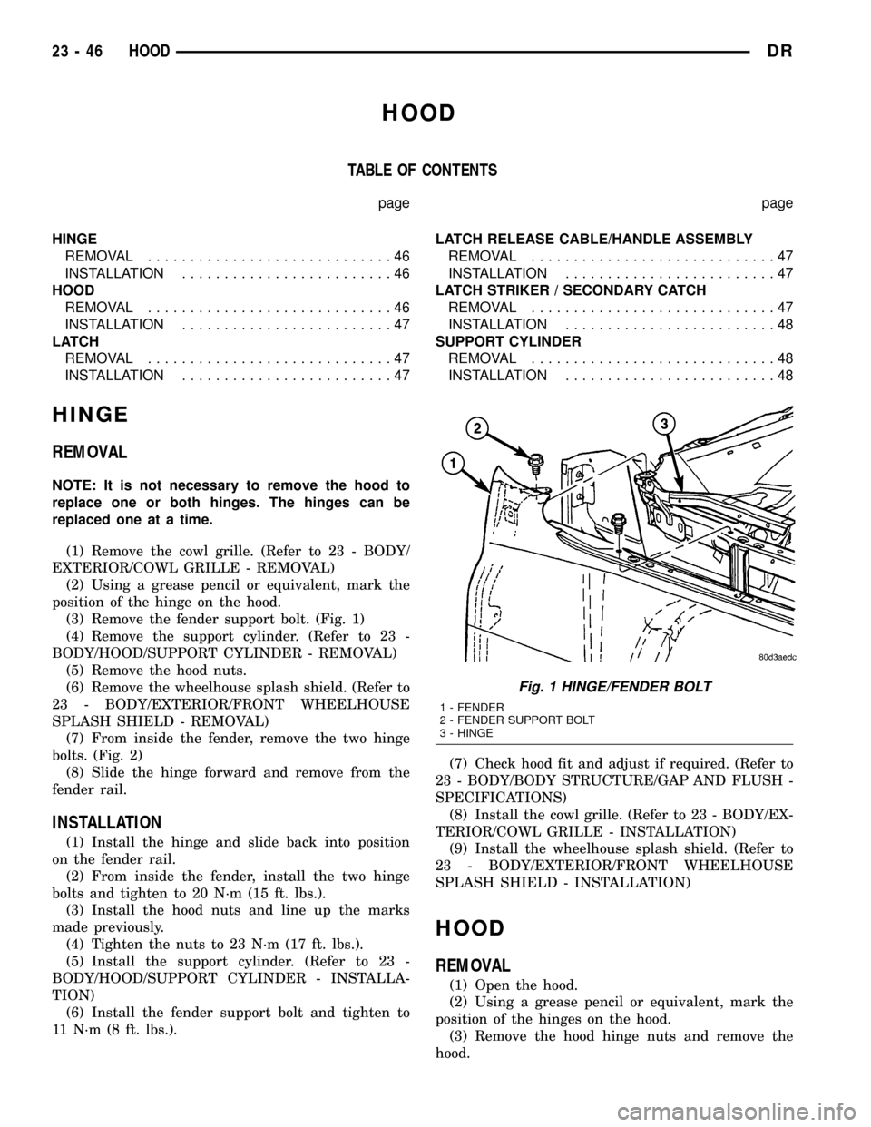
(3) Remove the fender support bolt. (Fig. 1)
(4) Remove the support cylinder. (Refer to 23 -
BODY/HOOD/SUPPORT CYLINDER - REMOVAL)
(5) Remove the hood nuts.
(6) Remove the wheelhouse splash shield. (Refer to
23 - BODY/EXTERIOR/FRONT WHEELHOUSE
SPLASH SHIELD - REMOVAL)
(7) From inside the fender, remove the two hinge
bolts. (Fig. 2)
(8) Slide the hinge forward and remove from the
fender rail.
INSTALLATION
(1) Install the hinge and slide back into position
on the fender rail.
(2) From inside the fender, install the two hinge
bolts and tighten to 20 N´m (15 ft. lbs.).
(3) Install the hood nuts and line up the marks
made previously.
(4) Tighten the nuts to 23 N´m (17 ft. lbs.).
(5) Install the support cylinder. (Refer to 23 -
BODY/HOOD/SUPPORT CYLINDER - INSTALLA-
TION)
(6) Install the fender support bolt and tighten to
11 N´m (8 ft. lbs.).(7) Check hood fit and adjust if required. (Refer to
23 - BODY/BODY STRUCTURE/GAP AND FLUSH -
SPECIFICATIONS)
(8) Install the cowl grille. (Refer to 23 - BODY/EX-
TERIOR/COWL GRILLE - INSTALLATION)
(9) Install the wheelhouse splash shield. (Refer to
23 - BODY/EXTERIOR/FRONT WHEELHOUSE
SPLASH SHIELD - INSTALLATION)
HOOD
REMOVAL
(1) Open the hood.
(2) Using a grease pencil or equivalent, mark the
position of the hinges on the hood.
(3) Remove the hood hinge nuts and remove the
hood.
Fig. 1 HINGE/FENDER BOLT
1 - FENDER
2 - FENDER SUPPORT BOLT
3 - HINGE
23 - 46 HOODDR
Page 2344 of 2627

INSTRUMENT PANEL
TABLE OF CONTENTS
page page
CLUSTER BEZEL
REMOVAL.............................49
INSTALLATION.........................49
ASH RECEIVER
REMOVAL.............................50
INSTALLATION.........................51
CUP HOLDER
REMOVAL.............................51
INSTALLATION.........................51
GLOVE BOX
REMOVAL.............................52
INSTALLATION.........................52
GLOVE BOX LATCH
REMOVAL.............................52
INSTALLATION.........................52
INSTRUMENT PANEL ASSEMBLY
REMOVAL.............................52
INSTALLATION.........................55
INSTRUMENT PANEL HEADLAMP SWITCH
BEZEL
REMOVAL.............................56
INSTALLATION.........................56INSTRUMENT PANEL CENTER BEZEL
REMOVAL.............................57
INSTALLATION.........................57
INSTRUMENT PANEL DRIVER SIDE BEZEL
REMOVAL.............................58
INSTALLATION.........................58
INSTRUMENT PANEL TOP COVER
REMOVAL.............................58
INSTALLATION.........................59
INSTRUMENT PANEL LOWER SURROUND
REMOVAL.............................59
INSTALLATION.........................59
STEERING COLUMN OPENING COVER
REMOVAL.............................60
INSTALLATION.........................60
STEERING COLUMN OPENING SUPPORT
BRACKET
REMOVAL.............................60
INSTALLATION.........................60
STORAGE BIN
REMOVAL.............................61
INSTALLATION.........................61
CLUSTER BEZEL
REMOVAL
WARNING: ON VEHICLES EQUIPPED WITH AIR-
BAGS, DISABLE THE AIRBAG SYSTEM BEFORE
ATTEMPTING ANY STEERING WHEEL, STEERING
COLUMN, SEAT BELT TENSIONER, OR INSTRU-
MENT PANEL COMPONENT DIAGNOSIS OR SER-
VICE. DISCONNECT AND ISOLATE THE BATTERY
NEGATIVE (GROUND) CABLE, THEN WAIT TWO
MINUTES FOR THE AIRBAG SYSTEM CAPACITOR
TO DISCHARGE BEFORE PERFORMING FURTHER
DIAGNOSIS OR SERVICE. THIS IS THE ONLY SURE
WAY TO DISABLE THE AIRBAG SYSTEM. FAILURE
TO TAKE THE PROPER PRECAUTIONS COULD
RESULT IN ACCIDENTAL AIRBAG DEPLOYMENT
AND POSSIBLE PERSONAL INJURY.
(1) Remove the headlamp switch bezel. (Refer to
23 - BODY/INSTRUMENT PANEL/INSTRUMENT
PANEL SWITCH BEZEL - REMOVAL)
(2) Remove the center bezel. (Refer to 23 - BODY/
INSTRUMENT PANEL/INSTRUMENT PANEL
CENTER BEZEL - REMOVAL)(3) Remove the two top screws. (Fig. 1)
(4) Using a trim stick C-4755 or equivalent, sepa-
rate the two lower clips.
(5) Disengage the two top attachment bosses and
remove the bezel.
INSTALLATION
WARNING: ON VEHICLES EQUIPPED WITH AIR-
BAGS, DISABLE THE AIRBAG SYSTEM BEFORE
ATTEMPTING ANY STEERING WHEEL, STEERING
COLUMN, SEAT BELT TENSIONER, OR INSTRU-
MENT PANEL COMPONENT DIAGNOSIS OR SER-
VICE. DISCONNECT AND ISOLATE THE BATTERY
NEGATIVE (GROUND) CABLE, THEN WAIT TWO
MINUTES FOR THE AIRBAG SYSTEM CAPACITOR
TO DISCHARGE BEFORE PERFORMING FURTHER
DIAGNOSIS OR SERVICE. THIS IS THE ONLY SURE
WAY TO DISABLE THE AIRBAG SYSTEM. FAILURE
TO TAKE THE PROPER PRECAUTIONS COULD
RESULT IN ACCIDENTAL AIRBAG DEPLOYMENT
AND POSSIBLE PERSONAL INJURY.
(1) Position the cluster bezel over the cluster and
seat the outer bosses over the posts on the left and
right sides.
DRINSTRUMENT PANEL 23 - 49
Page 2357 of 2627

INTERIOR
TABLE OF CONTENTS
page page
INTERIOR
CAUTION.............................62
4WD FLOOR SHIFT BOOT
REMOVAL.............................62
INSTALLATION.........................62
A-PILLAR TRIM/GRAB HANDLE
REMOVAL.............................63
INSTALLATION.........................63
B-PILLAR LOWER TRIM
REMOVAL.............................63
INSTALLATION.........................64
B-PILLAR UPPER TRIM
REMOVAL.............................64
INSTALLATION.........................64
CARPETS AND FLOOR MATS
REMOVAL.............................65
INSTALLATION.........................65
COAT HOOK
REMOVAL.............................66
INSTALLATION.........................66
COWL TRIM
REMOVAL.............................66
INSTALLATION.........................66
C-PILLAR LOWER TRIM
REMOVAL.............................66
INSTALLATION.........................67
C-PILLAR UPPER TRIM
REMOVAL.............................67
INSTALLATION.........................67
FLOOR CONSOLE
REMOVAL.............................67
INSTALLATION.........................67
HEADLINER
REMOVAL.............................68INSTALLATION.........................68
B-PILLAR GRAB HANDLE
REMOVAL.............................68
INSTALLATION.........................68
REAR CAB BACK PANEL TRIM
REMOVAL.............................68
INSTALLATION.........................69
REAR VIEW MIRROR
REMOVAL.............................69
INSTALLATION
INSTALLATION.......................70
INSTALLATION - REAR VIEW MIRROR
SUPPORT BRACKET...................70
SUN VISOR
REMOVAL.............................70
INSTALLATION.........................70
SUN VISOR SUPPORT
REMOVAL.............................70
INSTALLATION.........................71
BODY VENT
REMOVAL.............................71
INSTALLATION.........................71
REAR DOOR SILL TRIM COVER
REMOVAL.............................71
INSTALLATION.........................71
LOAD FLOOR
REMOVAL.............................71
INSTALLATION.........................72
LOAD FLOOR SUPPORT CYLINDER
REMOVAL.............................72
INSTALLATION.........................72
INTERIOR
CAUTION
CAUTION:: Do not attempt to remove interior trim
panels/moldings without first removing the neces-
sary adjacent panels. To avoid damaging the pan-
els, ensure that all the screws and clips are
removed before attempting to remove an interior
trim panel/molding. Trim panels are somewhat flex-
ible but can be damaged if handled improperly.
4WD FLOOR SHIFT BOOT
REMOVAL
(1) Using a small pry bar or equivalent, remove
the insert, the nut and remove the shifter knob. (Fig.
2)
(2) Using a trim stick C-4755 or equivalent, pry up
the boot from the console. (Fig. 1)
INSTALLATION
(1) Position the shift boot over the shifter lever
fully seat onto the console.
23 - 62 INTERIORDR
Page 2368 of 2627

PAINT
TABLE OF CONTENTS
page page
PAINT
SPECIFICATIONS - PAINT CODES..........73
PAINT CODE
DESCRIPTION.........................73
BASECOAT/CLEARCOAT FINISH
DESCRIPTION.........................73PAINT TOUCH-UP
DESCRIPTION.........................74
STANDARD PROCEDURE - PAINT TOUCH-UP . 74
FINESSE SANDING/BUFFING & POLISHING
DESCRIPTION.........................74
PAINT
SPECIFICATIONS - PAINT CODES
NOTE: Because of late model changes to the avail-
able paint colors (Refer to VEHICLE DATA/VEHICLE
INFORMATION/VEHICLE CERTIFICATION LABEL -
DESCRIPTION) or (Refer to VEHICLE DATA/VEHI-
CLE INFORMATION/BODY CODE PLATE - DESCRIP-
TION) for the correct paint codes for each vehicle.
(Refer to 23 - BODY/PAINT/PAINT CODE - DESCRIP-
TION)
EXTERIOR COLORS
EXTERIOR COLOR DAIMLERCHRYSLER
CODE
Deep Molten Red
PearlcoatBR8
Flame Red Clearcoat PR4
Light Almond Pearl
Metallic ClearcoatZKJ
Atlantic Blue Pearlcoat ZBJ
Patriot Blue Pearlcoat WBT/WB7
Graphite Metallic
ClearcoatZDR
Bright Silver Metallic
ClearcoatWSB/WS2
Black Clearcoat DX8
Bright White Clearcoat GW7
Timberline Green AGW
INTERIOR COLORS
INTERIOR COLOR DAIMLERCHRYSLER
CODE
Taupe L5
Dark Slate Gray DV
PAINT CODE
DESCRIPTION
Exterior vehicle body colors are identified on the
Vehicle Certification Label (Refer to VEHICLE
DATA/VEHICLE INFORMATION/VEHICLE CERTI-
FICATION LABEL - DESCRIPTION) or the Body
Code Plate (Refer to VEHICLE DATA/VEHICLE
INFORMATION/BODY CODE PLATE - DESCRIP-
TION). The first digit of the paint code listed on the
vehicle indicates the sequence of application, i.e.: P =
primary coat, Q = secondary coat. The color names
provided in the Paint and Trim Code Description
chart are the color names used on most repair prod-
uct containers. (Refer to 23 - BODY/PAINT - SPECI-
FICATIONS)
BASECOAT/CLEARCOAT
FINISH
DESCRIPTION
The original equipment finish is a multi step pro-
cess that involves cleaning, applying electro de-posi-
tion (E-coat), anti-chip primer, basecoat, and
clearcoat steps.
On most vehicles a two-part paint application
(basecoat/clearcoat) is used. Color paint that is
applied to primer is called basecoat. The clear coat
protects the basecoat from ultraviolet light and pro-
vides a durable high-gloss finish.
DRPAINT 23 - 73
Page 2370 of 2627

SEATS
TABLE OF CONTENTS
page page
CENTER SEAT
REMOVAL.............................75
INSTALLATION.........................76
CENTER ARMREST / SEAT BACK
REMOVAL.............................76
INSTALLATION.........................77
CENTER SEAT BACK INERTIA HINGE COVER
REMOVAL.............................77
INSTALLATION.........................77
CENTER SEAT BACK HINGE
REMOVAL.............................78
INSTALLATION.........................79
CENTER SEAT BACK LID
REMOVAL.............................79
INSTALLATION.........................79
CENTER SEAT CUSHION
REMOVAL.............................79
INSTALLATION.........................79
CENTER SEAT CUSHION COVER
REMOVAL.............................79
INSTALLATION.........................79
UNDER SEAT STORAGE BIN LID
REMOVAL.............................80
INSTALLATION.........................80
UNDER SEAT STORAGE BIN
REMOVAL.............................80
INSTALLATION.........................80
UNDER SEAT STORAGE BIN COVERING
REMOVAL.............................80
INSTALLATION.........................80
UNDER SEAT STORAGE BIN LATCH
REMOVAL.............................80
INSTALLATION.........................80
HEADREST
REMOVAL.............................80
INSTALLATION.........................80
HEADREST SLEEVE
REMOVAL.............................81INSTALLATION.........................81
SEAT - FRONT
REMOVAL.............................81
INSTALLATION.........................81
LUMBAR SUPPORT HANDLE/BEZEL
REMOVAL.............................82
INSTALLATION.........................82
SEAT BACK CUSHION / COVER - FRONT
REMOVAL.............................82
INSTALLATION.........................82
SEAT CUSHION / COVER - FRONT
REMOVAL.............................83
INSTALLATION.........................83
SEAT TRACK
REMOVAL.............................83
INSTALLATION.........................83
SEAT - REAR
REMOVAL.............................83
INSTALLATION.........................83
SEAT BACK - REAR
REMOVAL.............................83
INSTALLATION.........................83
SEAT BACK CUSHION / COVER - REAR
REMOVAL.............................84
INSTALLATION.........................84
SEAT CUSHION / COVER - REAR
REMOVAL.............................84
INSTALLATION.........................84
SEAT CUSHION FRAME - REAR
REMOVAL.............................85
INSTALLATION.........................85
SEAT BACK REAR - FOOTMANS LOOP
BRACKETS
REMOVAL.............................85
INSTALLATION.........................85
CENTER SEAT
REMOVAL
NOTE: Do not reuse the seat fasteners, always
replace with new ones.
(1) Remove and discard the front bolts. (Fig. 1)(2) Position the seats forward, remove the rear
bolts and discard.
(3) Disconnect the 12v power supply electrical con-
nector, if equipped. (Fig. 2)
(4) Fold the seat backs forward and roll the seat
assembly back in the vehicle.
(5) Remove the nuts attaching the center seat to
the drivers seat and the passenger seat and discard.
(Fig. 3)
DRSEATS 23 - 75
Page 2381 of 2627

STATIONARY GLASS
TABLE OF CONTENTS
page page
BACKLITE
REMOVAL.............................86
INSTALLATION.........................86
BACKLITE VENT GLASS
REMOVAL.............................87
INSTALLATION.........................87WINDSHIELD
WARNING
WINDSHIELD SAFETY PRECAUTIONS.....88
REMOVAL.............................88
INSTALLATION.........................88
BACKLITE
REMOVAL
It is difficult to salvage the backlite during the
removal operation. The backlite is part of the struc-
tural support for the roof. The urethane bonding
used to secure the glass to the fence is difficult to cut
or clean from any surface. Since the molding is set in
urethane, it is unlikely it would be salvaged. Before
removing the backlite, check the availability from the
parts supplier.
The backlite is attached to the window frame with
urethane adhesive. The urethane adhesive is applied
cold and seals the surface area between the window
opening and the glass. The primer adheres the ure-
thane adhesive to the backlite.
(1) Roll down door glass.
(2) Remove headliner. (Refer to 23 - BODY/INTE-
RIOR/HEADLINER - REMOVAL).
(3) On standard cab models remove the upper
b-pillar trim. (Refer to 23 - BODY/INTERIOR/B-PIL-
LAR UPPER TRIM - REMOVAL)
(4) On quad cab models remove the upper c-pillar
trim. (Refer to 23 - BODY/INTERIOR/C-PILLAR
UPPER TRIM - REMOVAL)
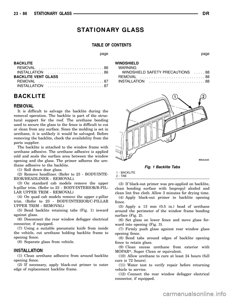
(5) Bend backlite retaining tabs (Fig. 1) inward
against glass.
(6) Disconnect the rear window defogger electrical
connector, if equipped.
(7) Using a suitable pneumatic knife from inside
the vehicle, cut urethane holding backlite frame to
opening fence.
(8) Separate glass from vehicle.
INSTALLATION
(1) Clean urethane adhesive from around backlite
opening fence.
(2) If necessary, apply black-out primer to outer
edge of replacement backlite frame.(3) If black-out primer was pre-applied on backlite,
clean bonding surface with Isopropyl alcohol and
clean lint free cloth. Allow 3 minutes for drying time.
(4) Apply black-out primer to backlite opening
fence.
(5) Apply a 13 mm (0.5 in.) bead of urethane
around the perimeter of the window frame bonding
surface (Fig. 2).
(6) Set glass on lower fence and move glass for-
ward into opening (Fig. 3).
(7) Firmly push glass against rear window glass
opening fence.
(8) Bend tabs around edges of backlite opening
fence to retain glass.
(9) Clean excess urethane from exterior with
MOPARt, Super Clean or equivalent.
(10) Allow urethane to cure at least 24 hours (full
cure is 72 hours).
(11) Water test to verify repair before returning
vehicle to service.
(12) Connect the rear window defogger electrical
connector, if equipped.
Fig. 1 Backlite Tabs
1 - BACKLITE
2-TAB
23 - 86 STATIONARY GLASSDR