1998 DODGE RAM 1500 ignition light
[x] Cancel search: ignition lightPage 1406 of 2627
DIAGNOSIS AND TESTING
DIAGNOSIS AND TESTING - ENGINE
DIAGNOSIS - INTRODUCTION
Engine diagnosis is helpful in determining the
causes of malfunctions not detected and remedied by
routine maintenance.
These malfunctions may be classified as either per-
formance (e.g., engine idles rough and stalls) or
mechanical (e.g., a strange noise).
(Refer to 9 - ENGINE - DIAGNOSIS AND TEST-
ING) - PERFORMANCE and (Refer to 9 - ENGINE -
DIAGNOSIS AND TESTING)ÐMECHANICAL for
possible causes and corrections of malfunctions.
(Refer to 14 - FUEL SYSTEM/FUEL DELIVERY -
DIAGNOSIS AND TESTING) and (Refer to 14 -
FUEL SYSTEM/FUEL INJECTION - DIAGNOSIS
AND TESTING) for the fuel system diagnosis.Additional tests and diagnostic procedures may be
necessary for specific engine malfunctions that can
not be isolated with the Service Diagnosis charts.
Information concerning additional tests and diagno-
sis is provided within the following diagnosis:
²Cylinder Compression Pressure Test (Refer to 9 -
ENGINE - DIAGNOSIS AND TESTING).
²Cylinder Combustion Pressure Leakage Test
(Refer to 9 - ENGINE - DIAGNOSIS AND TEST-
ING).
²Engine Cylinder Head Gasket Failure Diagnosis
(Refer to 9 - ENGINE/CYLINDER HEAD - DIAGNO-
SIS AND TESTING).
²Intake Manifold Leakage Diagnosis (Refer to 9 -
ENGINE/MANIFOLDS/INTAKE MANIFOLD -
DIAGNOSIS AND TESTING).
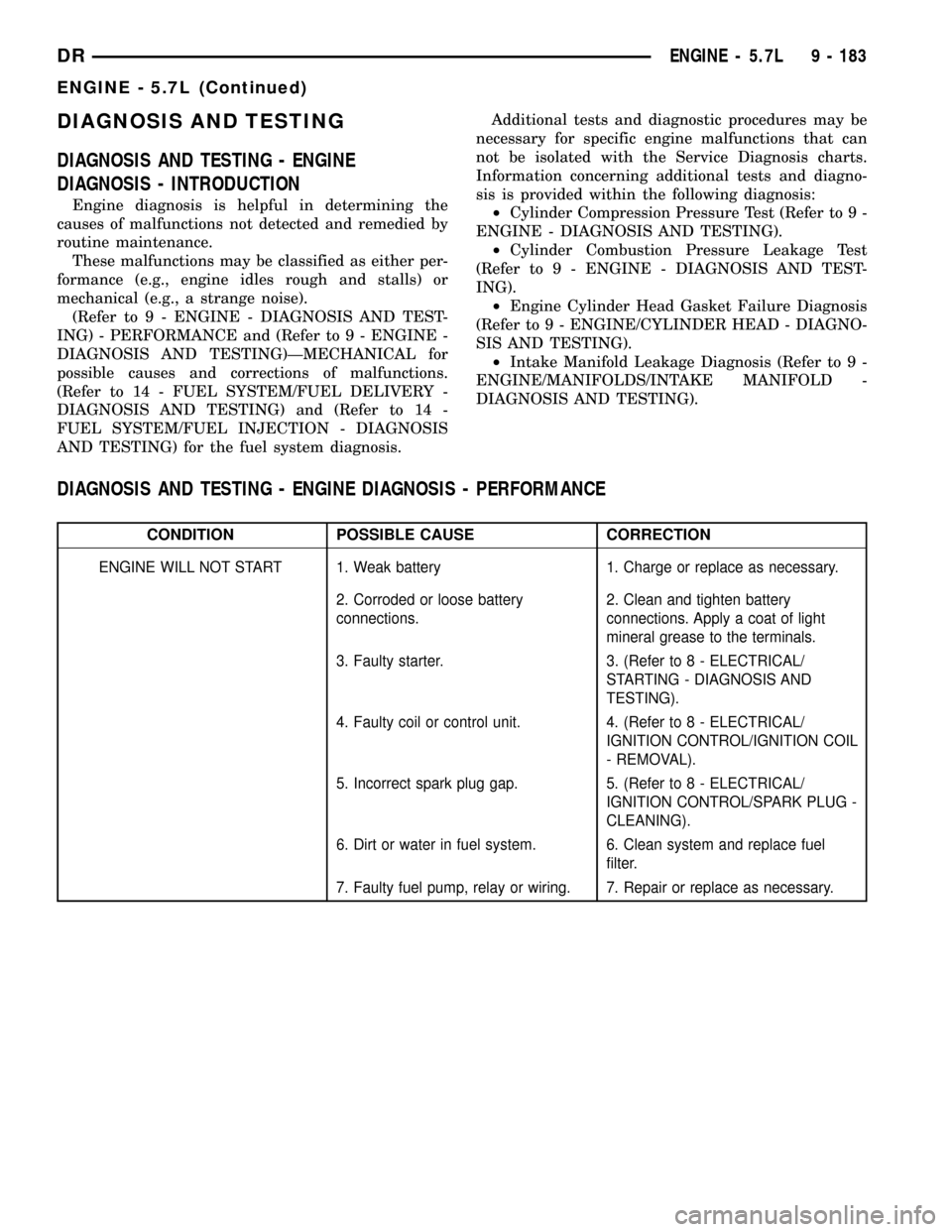
DIAGNOSIS AND TESTING - ENGINE DIAGNOSIS - PERFORMANCE
CONDITION POSSIBLE CAUSE CORRECTION
ENGINE WILL NOT START 1. Weak battery 1. Charge or replace as necessary.
2. Corroded or loose battery
connections.2. Clean and tighten battery
connections. Apply a coat of light
mineral grease to the terminals.
3. Faulty starter. 3. (Refer to 8 - ELECTRICAL/
STARTING - DIAGNOSIS AND
TESTING).
4. Faulty coil or control unit. 4. (Refer to 8 - ELECTRICAL/
IGNITION CONTROL/IGNITION COIL
- REMOVAL).
5. Incorrect spark plug gap. 5. (Refer to 8 - ELECTRICAL/
IGNITION CONTROL/SPARK PLUG -
CLEANING).
6. Dirt or water in fuel system. 6. Clean system and replace fuel
filter.
7. Faulty fuel pump, relay or wiring. 7. Repair or replace as necessary.
DRENGINE - 5.7L 9 - 183
ENGINE - 5.7L (Continued)
Page 1585 of 2627
(7) Install 4 fuel rail mounting bolts and tighten.
Refer to torque specifications.
(8) Install 6 ignition coils. Refer to Ignition Coil
Removal/Installation.
(9) Connect electrical connectors to throttle body.
(10) Connect electrical connectors at all fuel injec-
tors. To install connector, refer to (Fig. 17). Push con-
nector onto injector (1) and then push and lock red
colored slider (2). Verify connector is locked to injec-
tor by lightly tugging on connector.
(11) Connect necessary vacuum lines to throttle
body.
(12) Install air resonator mounting bracket near
front of throttle body (2 bolts).
(13) Connect fuel line latch clip and fuel line to
fuel rail. Refer to Quick-Connect Fittings.
(14) Install air box to throttle body.
(15) Install air duct to air box.
(16) Connect battery cable to battery.
(17) Start engine and check for leaks.
4.7L V-8
(1) If fuel injectors are to be installed, refer to Fuel
Injector Removal/Installation.
(2) Clean out fuel injector machined bores in
intake manifold.(3) Apply a small amount of engine oil to each fuel
injector o-ring. This will help in fuel rail installation.
(4) Position fuel rail/fuel injector assembly to
machined injector openings in cylinder head.
(5) Guide each injector into cylinder head. Be care-
ful not to tear injector o-rings.
(6) Pushrightside of fuel rail down until fuel
injectors have bottomed on cylinder head shoulder.
Pushleftfuel rail down until injectors have bot-
tomed on cylinder head shoulder.
(7) Install 4 fuel rail mounting bolts and tighten.
Refer to torque specifications.
(8) Install 8 ignition coils. Refer to Ignition Coil
Removal/Installation.
(9) Connect electrical connectors to throttle body.
(10) Connect electrical connectors at all fuel injec-
tors. To install connector, refer to (Fig. 17). Push con-
nector onto injector (1) and then push and lock red
colored slider (2). Verify connector is locked to injec-
tor by lightly tugging on connector.
(11) Connect necessary vacuum lines to throttle
body.
(12) Install air resonator mounting bracket near
front of throttle body (2 bolts).
(13) Connect fuel line latch clip and fuel line to
fuel rail. Refer to Quick-Connect Fittings.
(14) Install air box to throttle body.
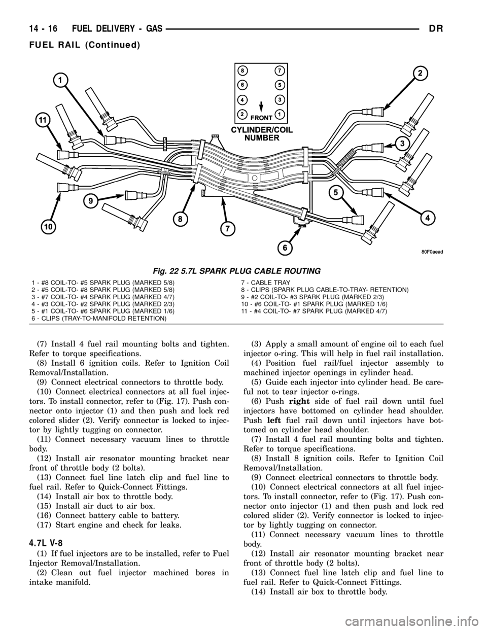
Fig. 22 5.7L SPARK PLUG CABLE ROUTING
1 - #8 COIL-TO- #5 SPARK PLUG (MARKED 5/8) 7 - CABLE TRAY
2 - #5 COIL-TO- #8 SPARK PLUG (MARKED 5/8) 8 - CLIPS (SPARK PLUG CABLE-TO-TRAY- RETENTION)
3 - #7 COIL-TO- #4 SPARK PLUG (MARKED 4/7) 9 - #2 COIL-TO- #3 SPARK PLUG (MARKED 2/3)
4 - #3 COIL-TO- #2 SPARK PLUG (MARKED 2/3) 10 - #6 COIL-TO- #1 SPARK PLUG (MARKED 1/6)
5 - #1 COIL-TO- #6 SPARK PLUG (MARKED 1/6) 11 - #4 COIL-TO- #7 SPARK PLUG (MARKED 4/7)
6 - CLIPS (TRAY-TO-MANIFOLD RETENTION)
14 - 16 FUEL DELIVERY - GASDR
FUEL RAIL (Continued)
Page 1586 of 2627

(15) Install air duct to air box.
(16) Connect battery cable to battery.
(17) Start engine and check for leaks.
5.7L V-8
(1) If fuel injectors are to be installed, refer to Fuel
Injector Removal/Installation.
(2) Clean out fuel injector machined bores in
intake manifold.
(3) Apply a small amount of engine oil to each fuel
injector o-ring. This will help in fuel rail installation.
(4) Position fuel rail/fuel injector assembly to
machined injector openings in intake manifold.
(5) Guide each injector into intake manifold. Be
careful not to tear injector o-rings.
(6) Pushrightside of fuel rail down until fuel
injectors have bottomed on shoulders. Pushleftfuel
rail down until injectors have bottomed on shoulders.
(7) Install 4 fuel rail holdown clamps and 4 mount-
ing bolts. Refer to Torque Specifications.
(8) Position spark plug cable tray and cable assem-
bly to intake manifold. Snap 4 cable tray retaining
clips into intake manifold.
(9) Install all cables to spark plugs and ignition
coils.
(10) Connect electrical connector to throttle body.
(11) Install electrical connectors to all 8 ignition
coils. Refer to Ignition Coil Removal/Installation.
(12) Connect electrical connector to throttle body.
(13) Connect electrical connectors at all fuel injec-
tors. To install connector, refer to (Fig. 17). Push con-
nector onto injector (1) and then push and lock red
colored slider (2). Verify connector is locked to injec-
tor by lightly tugging on connector.
(14) Connect fuel line latch clip and fuel line to
fuel rail. Refer to Quick-Connect Fittings.
(15) Install air resonator to throttle body (2 bolts).
(16) Install flexible air duct to air box.
(17) Connect battery cable to battery.
(18) Start engine and check for leaks.
FUEL TANK
DESCRIPTION
The fuel tank is constructed of a plastic material.
Its main functions are for fuel storage and for place-
ment of the fuel pump module, and (if equipped) cer-
tain ORVR components.
OPERATION
All models pass a full 360 degree rollover test
without fuel leakage. To accomplish this, fuel and
vapor flow controls are required for all fuel tank con-
nections.Two check (control) valves are mounted into the
top of the fuel tank. Refer to Fuel Tank Check Valve
for additional information.
An evaporation control system is connected to the
fuel tank to reduce emissions of fuel vapors into the
atmosphere. When fuel evaporates from the fuel
tank, vapors pass through vent hoses or tubes to a
charcoal canister where they are temporarily held.
When the engine is running, the vapors are drawn
into the intake manifold. Certain models are also
equipped with a self-diagnosing system using a Leak
Detection Pump (LDP) and/or an On-Board Refueling
Vapor Recovery (ORVR) system. Refer to Emission
Control System for additional information.
REMOVAL- EXCEPT DIESEL
Fuel Tank Draining
WARNING: THE FUEL SYSTEM MAY BE UNDER
CONSTANT FUEL PRESSURE EVEN WITH THE
ENGINE OFF. THIS PRESSURE MUST BE
RELEASED BEFORE SERVICING FUEL TANK.
Two different procedures may be used to drain fuel
tank: through the fuel fill fitting on tank, or using
the DRBtscan tool. Due to a one-way check valve
installed into the fuel fill opening fitting at the tank,
the tank cannot be drained conventionally at the fill
cap.
The quickest draining procedure involves removing
the rubber fuel fill hose.
As an alternative procedure, the electric fuel pump
may be activated allowing tank to be drained at fuel
rail connection. Refer to DRB scan tool for fuel pump
activation procedures. Before disconnecting fuel line
at fuel rail, release fuel pressure. Refer to the Fuel
System Pressure Release Procedure for procedures.
Attach end of special test hose tool number 6541,
6539, 6631 or 6923 at fuel rail disconnection (tool
number will depend on model and/or engine applica-
tion). Position opposite end of this hose tool to an
approved gasoline draining station. Activate fuel
pump and drain tank until empty.
If electric fuel pump is not operating, fuel must be
drained through fuel fill fitting at tank. Refer to fol-
lowing procedures.
(1) Release fuel system pressure.
(2) Raise vehicle.
(3) Thoroughly clean area around fuel fill fitting
and rubber fuel fill hose at tank.
(4) If vehicle is equipped with 4 doors and a 6 foot
(short) box, remove left-rear tire/wheel.
(5) Loosen clamp (Fig. 23) and disconnect rubber
fuel fill hose at tank fitting. Using an approved gas
holding tank, drain fuel tank through this fitting.
DRFUEL DELIVERY - GAS 14 - 17
FUEL RAIL (Continued)
Page 1620 of 2627

(b) Install new o-ring to canister lid and lubri-
cate o-ring with clean engine oil.
(c) Position new element to canister lid. Place
this assembly into canister by rotating clockwise.
(d) Tighten cap to 34 N´m (25 ft. lbs.) torque. Do
not overtighten cap.
(3)Water-In-Fuel (WIF) Sensor:
(a) Install new o-ring seal to WIF sensor.
(b) Apply a light film of clean oil to o-ring seal.
(c) Install sensor into housing.
(d) Tighten sensor to 2.5 N´m (25 in. lbs.) torque.
(e) Connect electrical connector to WIF sensor.
(4)Fuel Heater Element:
(a) Install fuel heater into fuel filter housing.
(b) Install fuel heater thermostat into fuel filter
housing.
(c) Install fuel heater mounting screws and
tighten to 1-1.5 N´m (13 in. lbs.) torque.
(d) Connect electrical connector to fuel heater
thermostat.
(e) Install new filter cover O-ring onto fuel filter
housing cover and lubricate with clean engine oil.
(f) Tighten fuel filter housing cover (lid) to 34
N´m (25 ft. lbs.).
(5)Drain Valve:
(a) Install 2 new o-rings to valve and filter hous-
ing.
(b) Lubricate with silicon grease.
(c) Install fuel drain valve.
(d) Install 4 mounting screws and tighten to
1±1.5 N´m (8±13 in. lbs.) torque.
(e) Connect drain hose to drain valve.
(6) Start engine and check for leaks.
FUEL HEATER
DESCRIPTION
The fuel heater assembly is located on the side of
the fuel filter housing (Fig. 3).
The heater/element assembly is equipped with a
temperature sensor (thermostat) that senses fuel
temperature. This sensor is attached to the fuel heat-
er/element assembly.
OPERATION
The fuel heater is used to prevent diesel fuel from
waxing during cold weather operation.
When the temperature is below 45 8 degrees F,
the temperature sensor allows current to flow to the
heater element warming the fuel. When the temper-
ature is above 75 8 degrees F, the sensor stops cur-
rent flow to the heater element.
Battery voltage to operate the fuel heater element
is supplied from the ignition switch and through the
fuel heater relay. Also refer to Fuel Heater Relay.
Fig. 3 FILTER HOUSING
1 - FILTER HOUSING
2 - FUEL HEATER AND THERMOSTAT
3 - FUEL HEATER MOUNTING SCREWS
4 - FUEL HEATER ELEC. CONNECTOR
5 - WIF SENSOR
6 - WIF SENSOR ELEC. CONNECTOR
7 - DRAIN HOSE
8 - DRAIN VALVE MOUNTING SCREWS
9 - DRAIN VALVE
Fig. 4 FILTER COVER (LID)
1 - FILTER COVER
2 - ATTACH SOCKET HERE
DRFUEL DELIVERY - DIESEL 14 - 51
FUEL FILTER / WATER SEPARATOR (Continued)
Page 1664 of 2627
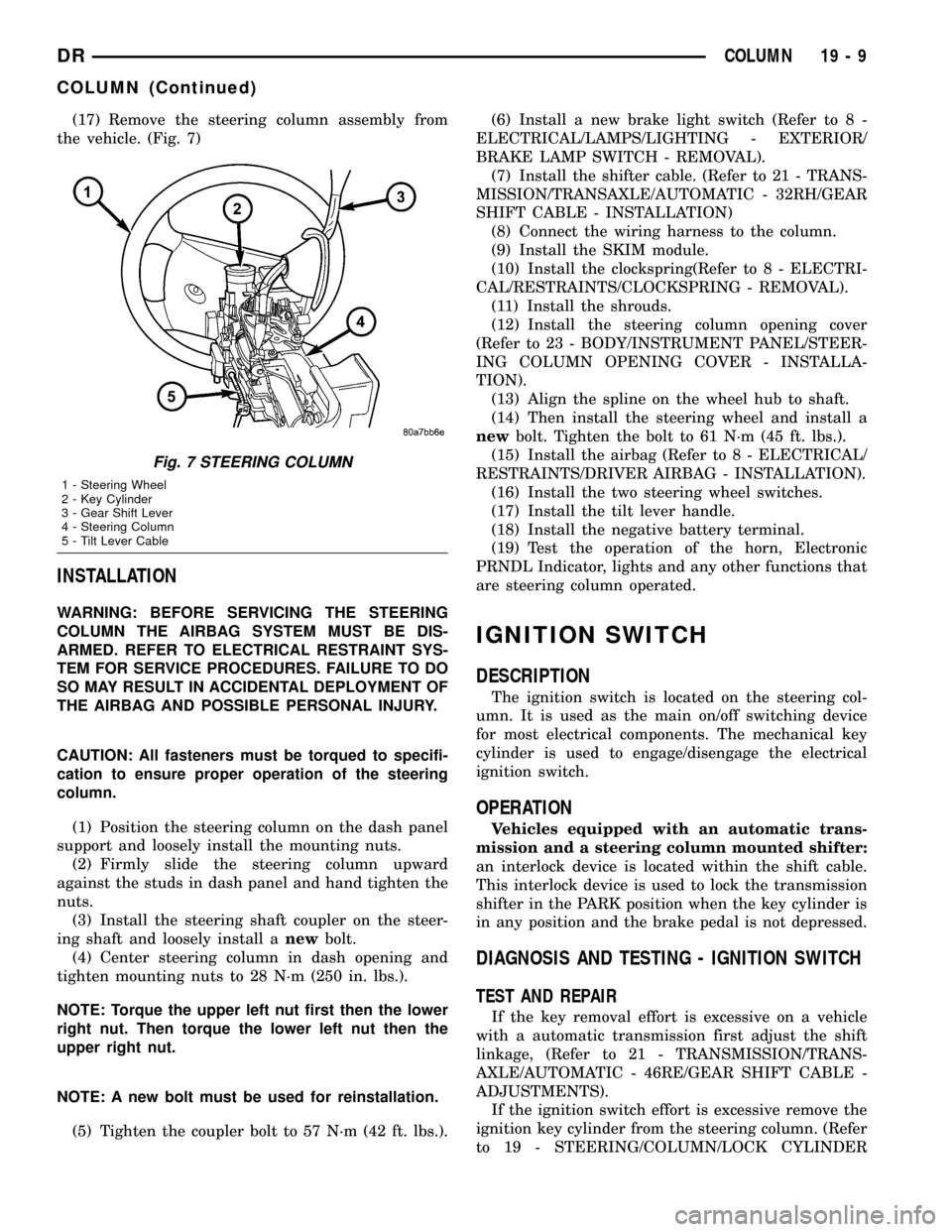
(17) Remove the steering column assembly from
the vehicle. (Fig. 7)
INSTALLATION
WARNING: BEFORE SERVICING THE STEERING
COLUMN THE AIRBAG SYSTEM MUST BE DIS-
ARMED. REFER TO ELECTRICAL RESTRAINT SYS-
TEM FOR SERVICE PROCEDURES. FAILURE TO DO
SO MAY RESULT IN ACCIDENTAL DEPLOYMENT OF
THE AIRBAG AND POSSIBLE PERSONAL INJURY.
CAUTION: All fasteners must be torqued to specifi-
cation to ensure proper operation of the steering
column.
(1) Position the steering column on the dash panel
support and loosely install the mounting nuts.
(2) Firmly slide the steering column upward
against the studs in dash panel and hand tighten the
nuts.
(3) Install the steering shaft coupler on the steer-
ing shaft and loosely install anewbolt.
(4) Center steering column in dash opening and
tighten mounting nuts to 28 N´m (250 in. lbs.).
NOTE: Torque the upper left nut first then the lower
right nut. Then torque the lower left nut then the
upper right nut.
NOTE: A new bolt must be used for reinstallation.
(5) Tighten the coupler bolt to 57 N´m (42 ft. lbs.).(6) Install a new brake light switch (Refer to 8 -
ELECTRICAL/LAMPS/LIGHTING - EXTERIOR/
BRAKE LAMP SWITCH - REMOVAL).
(7) Install the shifter cable. (Refer to 21 - TRANS-
MISSION/TRANSAXLE/AUTOMATIC - 32RH/GEAR
SHIFT CABLE - INSTALLATION)
(8) Connect the wiring harness to the column.
(9) Install the SKIM module.
(10) Install the clockspring(Refer to 8 - ELECTRI-
CAL/RESTRAINTS/CLOCKSPRING - REMOVAL).
(11) Install the shrouds.
(12) Install the steering column opening cover
(Refer to 23 - BODY/INSTRUMENT PANEL/STEER-
ING COLUMN OPENING COVER - INSTALLA-
TION).
(13) Align the spline on the wheel hub to shaft.
(14) Then install the steering wheel and install a
newbolt. Tighten the bolt to 61 N´m (45 ft. lbs.).
(15) Install the airbag (Refer to 8 - ELECTRICAL/
RESTRAINTS/DRIVER AIRBAG - INSTALLATION).
(16) Install the two steering wheel switches.
(17) Install the tilt lever handle.
(18) Install the negative battery terminal.
(19) Test the operation of the horn, Electronic
PRNDL Indicator, lights and any other functions that
are steering column operated.
IGNITION SWITCH
DESCRIPTION
The ignition switch is located on the steering col-
umn. It is used as the main on/off switching device
for most electrical components. The mechanical key
cylinder is used to engage/disengage the electrical
ignition switch.
OPERATION
Vehicles equipped with an automatic trans-
mission and a steering column mounted shifter:
an interlock device is located within the shift cable.
This interlock device is used to lock the transmission
shifter in the PARK position when the key cylinder is
in any position and the brake pedal is not depressed.
DIAGNOSIS AND TESTING - IGNITION SWITCH
TEST AND REPAIR
If the key removal effort is excessive on a vehicle
with a automatic transmission first adjust the shift
linkage, (Refer to 21 - TRANSMISSION/TRANS-
AXLE/AUTOMATIC - 46RE/GEAR SHIFT CABLE -
ADJUSTMENTS).
If the ignition switch effort is excessive remove the
ignition key cylinder from the steering column. (Refer
to 19 - STEERING/COLUMN/LOCK CYLINDER
Fig. 7 STEERING COLUMN
1 - Steering Wheel
2 - Key Cylinder
3 - Gear Shift Lever
4 - Steering Column
5 - Tilt Lever Cable
DRCOLUMN 19 - 9
COLUMN (Continued)
Page 1667 of 2627
KEY CYLINDER
REMOVAL
The ignition key must be in the key cylinder for
cylinder removal.
(1) Disconnect negative cable from battery.
(2) Remove upper and lower covers (shrouds) from
steering column.
(3) Place shifter in PARK position.
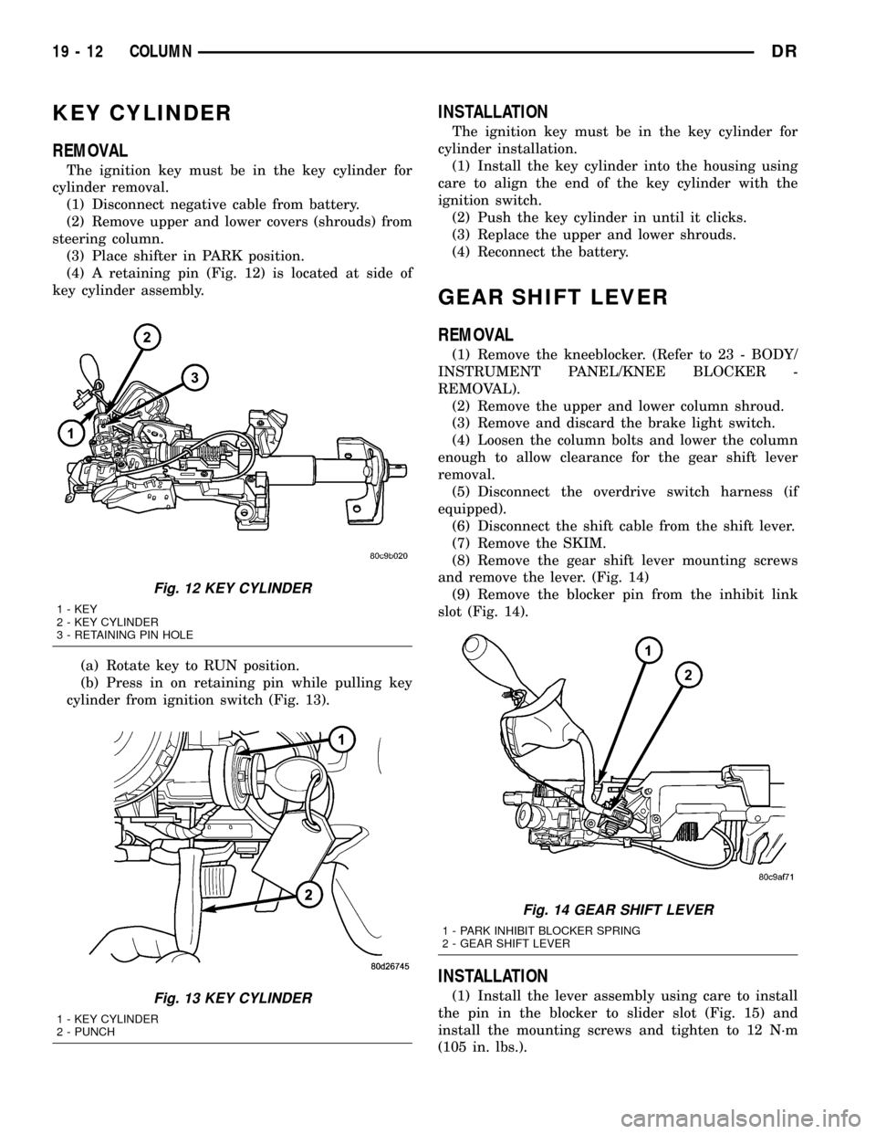
(4) A retaining pin (Fig. 12) is located at side of
key cylinder assembly.
(a) Rotate key to RUN position.
(b) Press in on retaining pin while pulling key
cylinder from ignition switch (Fig. 13).
INSTALLATION
The ignition key must be in the key cylinder for
cylinder installation.
(1) Install the key cylinder into the housing using
care to align the end of the key cylinder with the
ignition switch.
(2) Push the key cylinder in until it clicks.
(3) Replace the upper and lower shrouds.
(4) Reconnect the battery.
GEAR SHIFT LEVER
REMOVAL
(1) Remove the kneeblocker. (Refer to 23 - BODY/
INSTRUMENT PANEL/KNEE BLOCKER -
REMOVAL).
(2) Remove the upper and lower column shroud.
(3) Remove and discard the brake light switch.
(4) Loosen the column bolts and lower the column
enough to allow clearance for the gear shift lever
removal.
(5) Disconnect the overdrive switch harness (if
equipped).
(6) Disconnect the shift cable from the shift lever.
(7) Remove the SKIM.
(8) Remove the gear shift lever mounting screws
and remove the lever. (Fig. 14)
(9) Remove the blocker pin from the inhibit link
slot (Fig. 14).
INSTALLATION
(1) Install the lever assembly using care to install
the pin in the blocker to slider slot (Fig. 15) and
install the mounting screws and tighten to 12 N´m
(105 in. lbs.).
Fig. 12 KEY CYLINDER
1 - KEY
2 - KEY CYLINDER
3 - RETAINING PIN HOLE
Fig. 13 KEY CYLINDER
1 - KEY CYLINDER
2 - PUNCH
Fig. 14 GEAR SHIFT LEVER
1 - PARK INHIBIT BLOCKER SPRING
2 - GEAR SHIFT LEVER
19 - 12 COLUMNDR
Page 1668 of 2627
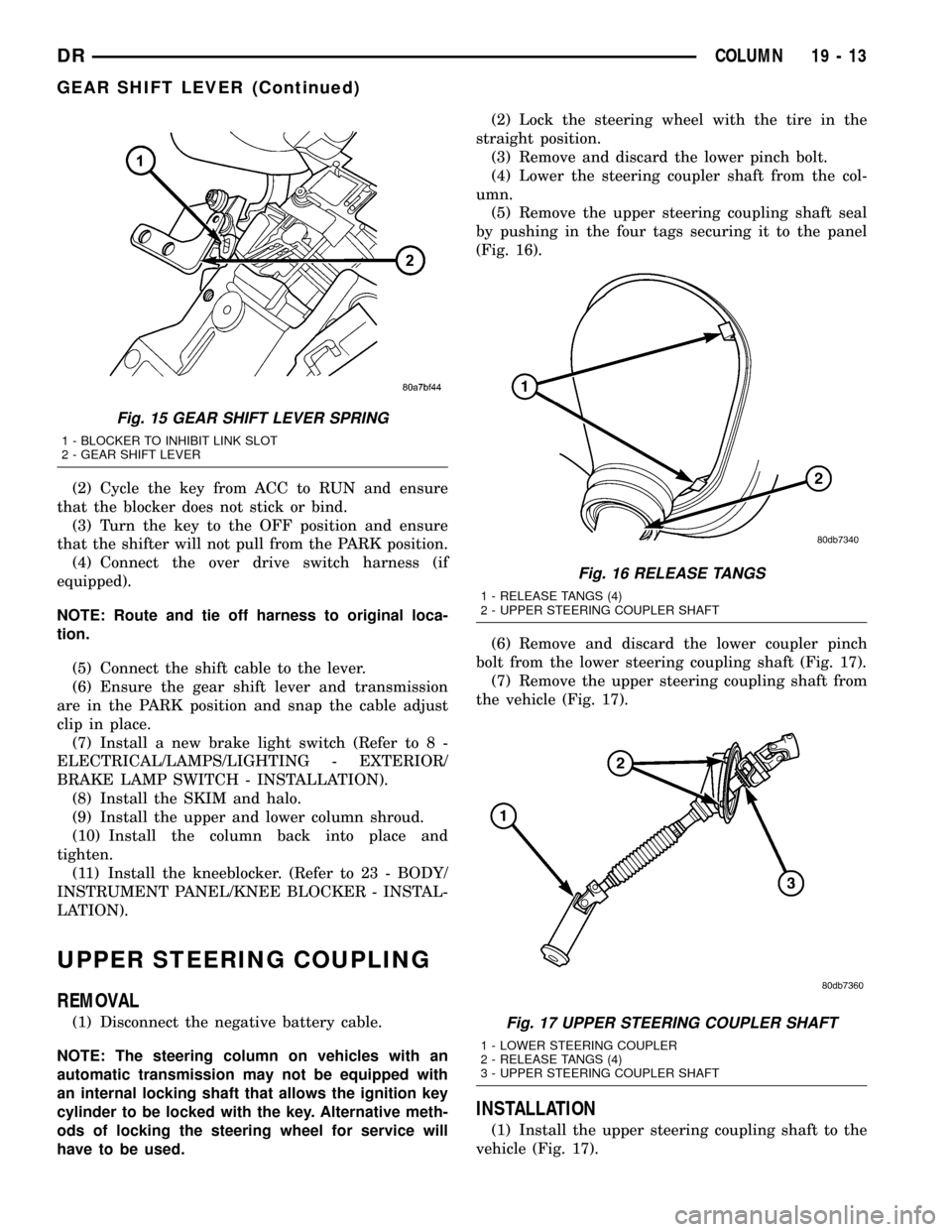
(2) Cycle the key from ACC to RUN and ensure
that the blocker does not stick or bind.
(3) Turn the key to the OFF position and ensure
that the shifter will not pull from the PARK position.
(4) Connect the over drive switch harness (if
equipped).
NOTE: Route and tie off harness to original loca-
tion.
(5) Connect the shift cable to the lever.
(6) Ensure the gear shift lever and transmission
are in the PARK position and snap the cable adjust
clip in place.
(7) Install a new brake light switch (Refer to 8 -
ELECTRICAL/LAMPS/LIGHTING - EXTERIOR/
BRAKE LAMP SWITCH - INSTALLATION).
(8) Install the SKIM and halo.
(9) Install the upper and lower column shroud.
(10) Install the column back into place and
tighten.
(11) Install the kneeblocker. (Refer to 23 - BODY/
INSTRUMENT PANEL/KNEE BLOCKER - INSTAL-
LATION).
UPPER STEERING COUPLING
REMOVAL
(1) Disconnect the negative battery cable.
NOTE: The steering column on vehicles with an
automatic transmission may not be equipped with
an internal locking shaft that allows the ignition key
cylinder to be locked with the key. Alternative meth-
ods of locking the steering wheel for service will
have to be used.(2) Lock the steering wheel with the tire in the
straight position.
(3) Remove and discard the lower pinch bolt.
(4) Lower the steering coupler shaft from the col-
umn.
(5) Remove the upper steering coupling shaft seal
by pushing in the four tags securing it to the panel
(Fig. 16).
(6) Remove and discard the lower coupler pinch
bolt from the lower steering coupling shaft (Fig. 17).
(7) Remove the upper steering coupling shaft from
the vehicle (Fig. 17).
INSTALLATION
(1) Install the upper steering coupling shaft to the
vehicle (Fig. 17).
Fig. 15 GEAR SHIFT LEVER SPRING
1 - BLOCKER TO INHIBIT LINK SLOT
2 - GEAR SHIFT LEVER
Fig. 16 RELEASE TANGS
1 - RELEASE TANGS (4)
2 - UPPER STEERING COUPLER SHAFT
Fig. 17 UPPER STEERING COUPLER SHAFT
1 - LOWER STEERING COUPLER
2 - RELEASE TANGS (4)
3 - UPPER STEERING COUPLER SHAFT
DRCOLUMN 19 - 13
GEAR SHIFT LEVER (Continued)
Page 1958 of 2627

(6) Reconnect cable end to attachment stud. Then
with aid of a helper, observe movement of transmis-
sion throttle lever and lever on throttle body.
²If both levers move simultaneously from idle to
half-throttle and back to idle position, adjustment is
correct.
²If transmission throttle lever moves ahead of, or
lags behind throttle body lever, cable adjustment will
be necessary. Or, if throttle body lever prevents
transmission lever from returning to closed position,
cable adjustment will be necessary.
ADJUSTMENT PROCEDURE
(1) Turn ignition switch to OFF position.
(2) Remove air cleaner if necessary.
(3) Disconnect cable end from attachment stud.
Carefully slide cable off stud. Do not pry or pull
cable off.
(4) Verify that transmission throttle lever is in
fully closed position. Then be sure lever on throttle
body is at curb idle position.
(5) Pry the T.V. cable lock (A) into the UP position
(Fig. 226). This will unlock the cable and allow for
readjustment.
(6) Apply just enough tension on the T.V. cable (B)
to remove any slack in the cable.Pulling too tight
will cause the T.V. lever on the transmission to
move out of its idle position, which will result
in an incorrect T.V. cable adjustment.Slide the
sheath of the T.V. cable (D) back and forth until the
centerlines of the T.V. cable end (B) and the throttle
bell crank lever (C) are aligned within one millimeter
(1mm) (Fig. 226).
(7) While holding the T.V. cable in the set position
push the T.V. cable lock (A) into the down position
(Fig. 226). This will lock the present T.V. cable
adjustment.
NOTE: Be sure that as the cable is pulled forward
and centered on the throttle lever stud, the cable
housing moves smoothly with the cable. Due to the
angle at which the cable housing enters the spring
housing, the cable housing may bind slightly and
create an incorrect adjustment.
(8) Reconnect the T.V. cable (B) to the throttle
bellcrank lever (C).
(9) Check cable adjustment. Verify transmission
throttle lever and lever on throttle body move simul-
taneously.
TORQUE CONVERTER
DESCRIPTION
The torque converter (Fig. 227) is a hydraulic
device that couples the engine crankshaft to the
transmission. The torque converter consists of an
outer shell with an internal turbine, a stator, an
overrunning clutch, an impeller and an electronically
applied converter clutch. The converter clutch pro-
vides reduced engine speed and greater fuel economy
when engaged. Clutch engagement also provides
reduced transmission fluid temperatures. The torque
converter hub drives the transmission oil (fluid)
pump.
The torque converter is a sealed, welded unit that
is not repairable and is serviced as an assembly.
CAUTION: The torque converter must be replaced if
a transmission failure resulted in large amounts of
metal or fiber contamination in the fluid. If the fluid
is contaminated, flush the all transmission fluid
cooler(s) and lines.
Fig. 227 Torque Converter Assembly
1 - TURBINE
2 - IMPELLER
3 - HUB
4-STATOR
5 - FRONT COVER
6 - CONVERTER CLUTCH DISC
7 - DRIVE PLATE
DRAUTOMATIC TRANSMISSION - 48RE 21 - 255
THROTTLE VALVE CABLE (Continued)