1998 DODGE RAM 1500 Transfer case
[x] Cancel search: Transfer casePage 1516 of 2627

OIL COOLER & LINES
CLEANING
CLEANING AND INSPECTION
Clean the sealing surfaces.
Apply 483 kPa (70 psi) air pressure to the element
to check for leaks. If the element leaks, replace the
element.
OIL FILTER
REMOVAL
(1) Clean the area around the oil filter head.
Remove the filter from below using a cap-style filter
wrench.
(2) Clean the gasket surface of the filter head. The
filter canister O-Ring seal can stick on the filter
head. Make sure it is removed.
INSTALLATION
(1) Fill the oil filter element with clean oil before
installation. Use the same type oil that will be used
in the engine.
(2) Apply a light film of lubricating oil to the seal-
ing surface before installing the filter.
CAUTION: Mechanical over-tightening may distort
the threads or damage the filter element seal.
(3) Install the filter until it contacts the sealing
surface of the oil filter adapter. Tighten filter an
additional
1¤2turn.
OIL PAN
REMOVAL
(1) Disconnect the battery negative cables.
(2) Install engine support fixture # 8534.
(3) Raise vehicle on hoist.
(4) Disconnect starter cables from starter motor.
(5) Remove transmission and transfer case (if
equipped).
(6) Remove flywheel or flexplate.
(7) Remove starter motor (Refer to 8 - ELECTRI-
CAL/STARTING/STARTER MOTOR - REMOVAL)
and transmission adapter plate assembly.
WARNING: HOT OIL CAN CAUSE PERSONAL
INJURY.
(8) Drain the engine oil (Refer to 9 - ENGINE/LU-
BRICATION/OIL - STANDARD PROCEDURE).(9) Install the oil pan drain plug if sealing surface
is not damaged and tighten to 50 N´m (37 ft. lbs.)
torque.
(10) Remove oil pan bolts, break the pan to block
seal, and lower pan slightly and remove oil suction
tube fasteners.
(11) Remove oil pan and suction tube.
CLEANING
Remove all gasket material from the oil pan and
cylinder block sealing surfaces. Extra effort may be
required around T-joint areas. Clean oil pan and
flush suction tube with a suitable solvent.
INSPECTION
Inspect the oil pan, suction tube, and tube braces
for cracks and damage. Replace any defective compo-
nent. Inspect the oil drain plug and drain hole
threads. Inspect the oil pan sealing surface for
straightness. Repair any minor imperfections with a
ball-peen hammer. Do not attempt to repair an oil
pan by welding.
INSTALLATION
(1) Fill the T-joint between the pan rail/gear hous-
ing and pan rail/rear seal retainer with sealant. Use
MopartSilicone Rubber Adhesive Sealant or equiva-
lent.
(2) Place suction tube in oil pan and guide them
into place. Using a new tube to block gasket, install
and tighten the suction tube bolts by hand. Starting
with the oil pump inlet bolts, tighten the bolts to 24
N´m (18 ft. lbs.) torque. Tighten the remaining tube
brace bolts to 43 N´m (32 ft. lbs.) torque.
(3) Starting in the center and working outward,
tighten the oil pan bolts to 28 N´m (21 ft. lbs.)
torque.
(4) Install the flywheel housing assembly with the
starter motor attached and tighten bolts to 77 N´m
(57 ft. lbs.) torque.
(5) Connect starter motor cables.
(6) Install the flywheel or flexplate. Torque to 137
N´m (101 ft. lbs.).
(7) Install transmission and transfer case (if
equipped).
(8) Lower vehicle.
(9) Remove the engine support fixture # 8534.
(10) Install battery negative cables.
(11) Fill the crankcase with new engine oil.
(12) Start engine and check for leaks. Stop engine,
check oil level, and adjust, if necessary.
DRENGINE 5.9L DIESEL 9 - 293
Page 1538 of 2627

OPERATION
Exhaust gas pressure and energy drive the tur-
bine, which in turn drives a centrifugal compressor
that compresses the inlet air, and forces the air into
the engine through the charge air cooler and plumb-
ing. Since heat is a by-product of this compression,
the air must pass through a charge air cooler to cool
the incoming air and maintain power and efficiency.
Increasing air flow to the engine provides:
²Improved engine performance
²Lower exhaust smoke density
²Improved operating economy
²Altitude compensation
²Noise reduction.
The turbocharger also uses a wastegate (Fig. 16),
which regulates intake manifold air pressure and
prevents over boosting at high engine speeds. When
the wastegate valve is closed, all of the exhaust gases
flow through the turbine wheel. As the intake mani-
fold pressure increases, the wastegate actuator opens
the valve, diverting some of the exhaust gases away
from the turbine wheel. This limits turbine shaft
speed and air output from the impeller.
The turbocharger is lubricated by engine oil that is
pressurized, cooled, and filtered. The oil is delivered
to the turbocharger by a supply line that is tapped
into the oil filter head. The oil travels into the bear-
ing housing, where it lubricates the shaft and bear-
ings (Fig. 17). A return pipe at the bottom of the
bearing housing, routes the engine oil back to the
crankcase.
The most common turbocharger failure is bearing
failure related to repeated hot shutdowns with inad-
equate ªcool-downº periods. A sudden engine shut
down after prolonged operation will result in the
transfer of heat from the turbine section of the tur-
bocharger to the bearing housing. This causes the oil
to overheat and break down, which causes bearing
and shaft damage the next time the vehicle is
started.
Letting the engine idle after extended operation
allows the turbine housing to cool to normal operat-
ing temperature. The following chart should be used
as a guide in determining the amount of engine idle
time required to sufficiently cool down the turbo-
charger before shut down, depending upon the type
of driving and the amount of cargo.
Fig. 16 Wastegate Operation
1 - SIGNAL LINE
2 - EXHAUST BYPASS VALVE
3 - WASTEGATE
4 - EXHAUST
5 - TURBINE
DREXHAUST SYSTEM 11 - 13
TURBOCHARGER (Continued)
Page 1544 of 2627

FRAMES & BUMPERS
TABLE OF CONTENTS
page page
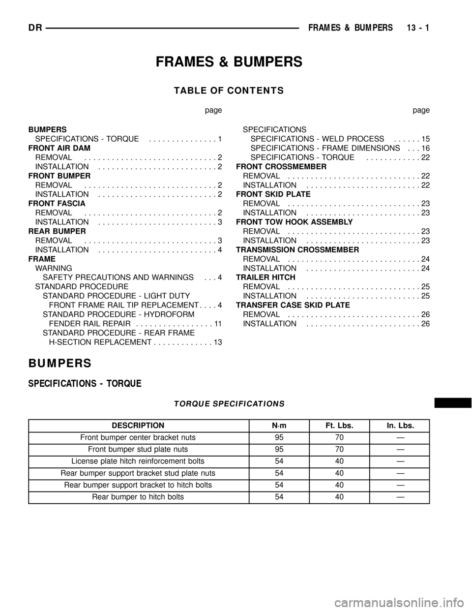
BUMPERS
SPECIFICATIONS - TORQUE...............1
FRONT AIR DAM
REMOVAL.............................2
INSTALLATION..........................2
FRONT BUMPER
REMOVAL.............................2
INSTALLATION..........................2
FRONT FASCIA
REMOVAL.............................2
INSTALLATION..........................3
REAR BUMPER
REMOVAL.............................3
INSTALLATION..........................4
FRAME
WARNING
SAFETY PRECAUTIONS AND WARNINGS . . . 4
STANDARD PROCEDURE
STANDARD PROCEDURE - LIGHT DUTY
FRONT FRAME RAIL TIP REPLACEMENT....4
STANDARD PROCEDURE - HYDROFORM
FENDER RAIL REPAIR.................11
STANDARD PROCEDURE - REAR FRAME
H-SECTION REPLACEMENT.............13SPECIFICATIONS
SPECIFICATIONS - WELD PROCESS......15
SPECIFICATIONS - FRAME DIMENSIONS . . . 16
SPECIFICATIONS - TORQUE............22
FRONT CROSSMEMBER
REMOVAL.............................22
INSTALLATION.........................22
FRONT SKID PLATE
REMOVAL.............................23
INSTALLATION.........................23
FRONT TOW HOOK ASSEMBLY
REMOVAL.............................23
INSTALLATION.........................23
TRANSMISSION CROSSMEMBER
REMOVAL.............................24
INSTALLATION.........................24
TRAILER HITCH
REMOVAL.............................25
INSTALLATION.........................25
TRANSFER CASE SKID PLATE
REMOVAL.............................26
INSTALLATION.........................26
BUMPERS
SPECIFICATIONS - TORQUE
TORQUE SPECIFICATIONS
DESCRIPTION N´m Ft. Lbs. In. Lbs.
Front bumper center bracket nuts 95 70 Ð
Front bumper stud plate nuts 95 70 Ð
License plate hitch reinforcement bolts 54 40 Ð
Rear bumper support bracket stud plate nuts 54 40 Ð
Rear bumper support bracket to hitch bolts 54 40 Ð
Rear bumper to hitch bolts 54 40 Ð
DRFRAMES & BUMPERS 13 - 1
Page 1565 of 2627

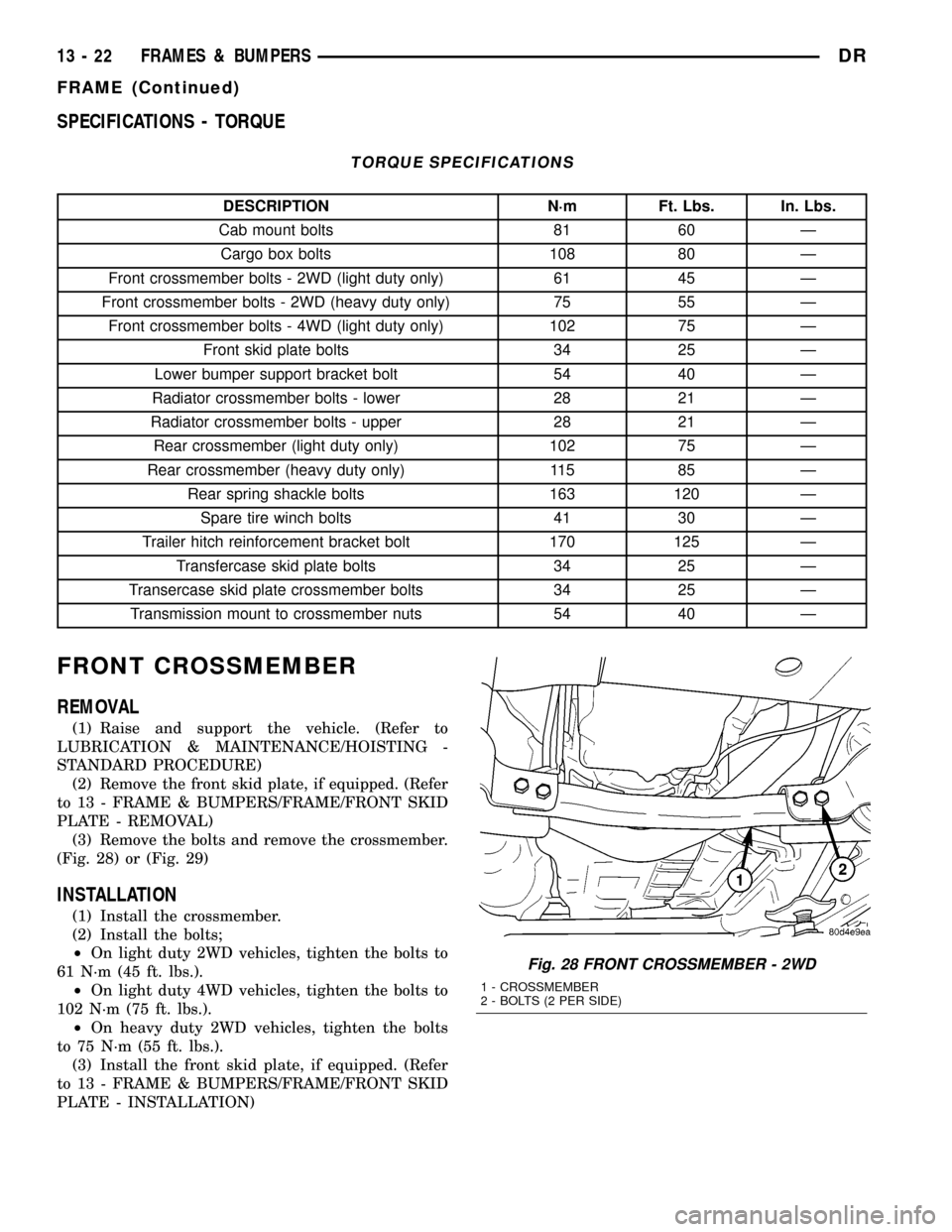
SPECIFICATIONS - TORQUE
TORQUE SPECIFICATIONS
DESCRIPTION N´m Ft. Lbs. In. Lbs.
Cab mount bolts 81 60 Ð
Cargo box bolts 108 80 Ð
Front crossmember bolts - 2WD (light duty only) 61 45 Ð
Front crossmember bolts - 2WD (heavy duty only) 75 55 Ð
Front crossmember bolts - 4WD (light duty only) 102 75 Ð
Front skid plate bolts 34 25 Ð
Lower bumper support bracket bolt 54 40 Ð
Radiator crossmember bolts - lower 28 21 Ð
Radiator crossmember bolts - upper 28 21 Ð
Rear crossmember (light duty only) 102 75 Ð
Rear crossmember (heavy duty only) 115 85 Ð
Rear spring shackle bolts 163 120 Ð
Spare tire winch bolts 41 30 Ð
Trailer hitch reinforcement bracket bolt 170 125 Ð
Transfercase skid plate bolts 34 25 Ð
Transercase skid plate crossmember bolts 34 25 Ð
Transmission mount to crossmember nuts 54 40 Ð
FRONT CROSSMEMBER
REMOVAL
(1) Raise and support the vehicle. (Refer to
LUBRICATION & MAINTENANCE/HOISTING -
STANDARD PROCEDURE)
(2) Remove the front skid plate, if equipped. (Refer
to 13 - FRAME & BUMPERS/FRAME/FRONT SKID
PLATE - REMOVAL)
(3) Remove the bolts and remove the crossmember.
(Fig. 28) or (Fig. 29)
INSTALLATION
(1) Install the crossmember.
(2) Install the bolts;
²On light duty 2WD vehicles, tighten the bolts to
61 N´m (45 ft. lbs.).
²On light duty 4WD vehicles, tighten the bolts to
102 N´m (75 ft. lbs.).
²On heavy duty 2WD vehicles, tighten the bolts
to 75 N´m (55 ft. lbs.).
(3) Install the front skid plate, if equipped. (Refer
to 13 - FRAME & BUMPERS/FRAME/FRONT SKID
PLATE - INSTALLATION)
Fig. 28 FRONT CROSSMEMBER - 2WD
1 - CROSSMEMBER
2 - BOLTS (2 PER SIDE)
13 - 22 FRAMES & BUMPERSDR
FRAME (Continued)
Page 1567 of 2627

TRANSMISSION
CROSSMEMBER
REMOVAL
(1) Raise and support the vehicle. (Refer to
LUBRICATION & MAINTENANCE/HOISTING -
STANDARD PROCEDURE)
(2) Remove the transfercase skid plate, if
equipped. (Refer to 13 - FRAME & BUMPERS/
FRAME/TRANSFER CASE SKID PLATE -
REMOVAL)
(3) Support the transmission with a suitable lifting
device.
(4) Remove the transmission mount nuts. (Fig. 33)
or (Fig. 34)
(5) Remove the bolts and remove the crossmember.
INSTALLATION
(1) Install the crossmember and install the bolts.
²On light duty vehicles, tighten the bolts to 102
N´m (75 ft. lbs.).
²On heavy duty vehicles, tighten the bolts to 115
N´m (85 ft. lbs.).
(2) Install the transmission mount nuts and
tighten to 54 N´m (40 ft. lbs.).(3) Remove the transmission support.
(4) Install the transfercase skid plate. (Refer to 13
- FRAME & BUMPERS/FRAME/TRANSFER CASE
SKID PLATE - INSTALLATION)
Fig. 32 FRONT TOW HOOK ASSEMBLY ± HEAVY
DUTY
1 - BOLTS (4 PER HOOK)
2 - HEAVY DUTY TOW HOOKS (2)
3 - BUMPER CENTER SUPPORT BRACKETS
Fig. 33 REAR CROSSMEMBER - 2WD
1 - TRANSMISSION MOUNT
2 - REAR CROSSMEMBER
3 - TRANSMISSION MOUNT NUTS (2)
4 - CROSSMEMBER BOLTS (2 PER SIDE)
Fig. 34 REAR CROSSMEMBER - 4WD
1 - TRANSMISSION MOUNT
2 - TORSION BAR
3 - CROSSMEMBER BOLTS (3 PER SIDE)
4 - REAR CROSSMEMBER
5 - TRANSMISSION MOUNT NUTS (2)
13 - 24 FRAMES & BUMPERSDR
FRONT TOW HOOK ASSEMBLY (Continued)
Page 1569 of 2627

TRANSFER CASE SKID PLATE
REMOVAL
(1) Raise and support the vehicle. (Refer to
LUBRICATION & MAINTENANCE/HOISTING -
STANDARD PROCEDURE)
(2) Support the skid plate and remove the bolts.
(Fig. 37)
(3) Remove the skid plate.
(4) Support the skid plate crossmember and
remove the bolts.
(5) Remove the skid plate crossmember.
INSTALLATION
(1) Install the skid plate crossmember and install
the bolts.
(2) Tighten the bolts to 34 N´m (25 ft. lbs.).
(3) Install the skid plate and install the bolts.
(4) Tighten the bolts to 34 N´m (25 ft. lbs.).
Fig. 37 TRANSFER CASE SKID PLATE
1 - CROSSMEMBER BOLTS (4)
2 - SKID PLATE CROSSMEMBER
3 - SKID PLATE
4 - SKID PLATE BOLTS (4)
Fig. 36 TRAILER HITCH ± HEAVY DUTY
1 - LOCATING TAB HOLE
2 - LOCATING PIN HOLE
3 - U-NUTS (2)
4 - BUMPER SUPPORT BRACKETS5 - HITCH
6 - HITCH TO FRAME NUTS (2)
7 - BUMPER BRACKET BOLTS (4)
8 - HITCH BOLTS (6)
13 - 26 FRAMES & BUMPERSDR
TRAILER HITCH (Continued)
Page 1704 of 2627

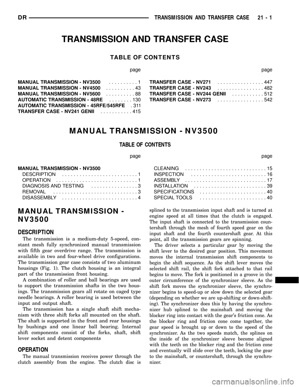
TRANSMISSION AND TRANSFER CASE
TABLE OF CONTENTS
page page
MANUAL TRANSMISSION - NV3500..........1
MANUAL TRANSMISSION - NV4500..........43
MANUAL TRANSMISSION - NV5600..........88
AUTOMATIC TRANSMISSION - 48RE........130
AUTOMATIC TRANSMISSION - 45RFE/545RFE.311
TRANSFER CASE - NV241 GENII...........415TRANSFER CASE - NV271................447
TRANSFER CASE - NV243................482
TRANSFER CASE - NV244 GENII...........512
TRANSFER CASE - NV273................542
MANUAL TRANSMISSION - NV3500
TABLE OF CONTENTS
page page
MANUAL TRANSMISSION - NV3500
DESCRIPTION..........................1
OPERATION............................1
DIAGNOSIS AND TESTING................3
REMOVAL.............................3
DISASSEMBLY..........................4CLEANING............................15
INSPECTION..........................16
ASSEMBLY............................17
INSTALLATION.........................39
SPECIFICATIONS.......................40
SPECIAL TOOLS.......................40
MANUAL TRANSMISSION -
NV3500
DESCRIPTION
The transmission is a medium-duty 5-speed, con-
stant mesh fully synchronized manual transmission
with fifth gear overdrive range. The transmission is
available in two and four-wheel drive configurations.
The transmission gear case consists of two aluminum
housings (Fig. 1). The clutch housing is an integral
part of the transmission front housing.
A combination of roller and ball bearings are used
to support the transmission shafts in the two hous-
ings. The transmission gears all rotate on caged type
needle bearings. A roller bearing is used between the
input and output shaft.
The transmission has a single shaft shift mecha-
nism with three shift forks all mounted on the shaft.
The shaft is supported in the front and rear housings
by bushings and one linear ball bearing. Internal
shift components consist of the forks, shaft, shift
lever socket and detent components
OPERATION
The manual transmission receives power through the
clutch assembly from the engine. The clutch disc issplined to the transmission input shaft and is turned at
engine speed at all times that the clutch is engaged.
The input shaft is connected to the transmission coun-
tershaft through the mesh of fourth speed gear on the
input shaft and the fourth countershaft gear. At this
point, all the transmission gears are spinning.
The driver selects a particular gear by moving the
shift lever to the desired gear position. This movement
moves the internal transmission shift components to
begin the shift sequence. As the shift lever moves the
selected shift rail, the shift fork attached to that rail
begins to move. The fork is positioned in a groove in the
outer circumference of the synchronizer sleeve. As the
shift fork moves the synchronizer sleeve, the synchro-
nizer begins to speed-up or slow down the selected gear
(depending on whether we are up-shifting or down-shift-
ing). The synchronizer does this by having the synchro-
nizer hub splined to the mainshaft and moving the
blocker ring into contact with the gear's friction cone. As
the blocker ring and friction cone come together, the
gear speed is brought up or down to the speed of the
synchronizer. As the two speeds match, the splines on
the inside of the synchronizer sleeve become aligned
with the teeth on the blocker ring and the friction cone
and eventually will slide over the teeth, locking the gear
to the mainshaft, or countershaft, through the synchro-
nizer.
DRTRANSMISSION AND TRANSFER CASE 21 - 1
Page 1706 of 2627

DIAGNOSIS AND TESTING
LOW LUBRICANT LEVEL
A low transmission lubricant level is generally the
result of a leak, inadequate lubricant fill or an incor-
rect lubricant level check. Leaks can occur at the
mating surfaces of the gear case, adaptor or exten-
sion housing, or from the front/rear seals. A sus-
pected leak could also be the result of an overfill
condition.
Leaks at the rear of the extension or adapter hous-
ing will be from the housing oil seals. Leaks at com-
ponent mating surfaces will probably be the result of
inadequate sealer, gaps in the sealer, incorrect bolt
tightening or use of a non-recommended sealer.
A leak at the front of the transmission will be from
either the front bearing retainer or retainer seal.
Lubricant may be seen dripping from the clutch
housing after extended operation. If the leak is
severe, it may also contaminate the clutch disc caus-
ing the disc to slip, grab and or chatter.
A correct lubricant level check can only be made
when the vehicle is level. Also allow the lubricant to
settle for a minute or so before checking. These rec-
ommendations will ensure an accurate check and
avoid an underfill or overfill condition. Always check
the lubricant level after any addition of fluid to avoid
an incorrect lubricant level condition.
HARD SHIFTING
Hard shifting is usually caused by a low lubricant
level, improper or contaminated lubricants. The con-
sequence of using non-recommended lubricants is
noise, excessive wear, internal bind and hard shift-
ing. Substantial lubricant leaks can result in gear,
shift rail, synchro, and bearing damage. If a leak
goes undetected for an extended period, the first indi-
cations of component damage are usually hard shift-
ing and noise.
Shift component damage or damaged clutch pres-
sure plate or disc are additional probable causes of
increased shift effort. Worn/damaged pressure plate
or disc can cause incorrect release. If clutch problem
is advanced, gear clash during shifts can result.
Worn or damaged synchro rings can cause gear clash
when shifting into any forward gear. In some new or
rebuilt transmissions, new synchro rings may tend to
stick slightly causing hard or noisy shifts. In most
cases this condition will decline as the rings wear-in.
TRANSMISSION NOISE
Most manual transmissions make some noise dur-
ing normal operation. Rotating gears generate a mild
whine that is audible, but generally only at extreme
speeds.
Severe highly audible transmission noise is gener-
ally the initial indicator of a lubricant problem.
Insufficient, improper or contaminated lubricant will
promote rapid wear of gears, synchros, shift rails,
forks and bearings. The overheating caused by a
lubricant problem, can also lead to gear and bearing
damage.
REMOVAL
(1) Disconnect battery negative cable.
(2) Shift transmission into Neutral.
(3) Remove shift boot bezel screws and slide boot
upward on shift lever extension.
(4) Remove shift lever extension from the shift
tower and lever assembly.
(5) Raise vehicle on hoist.
(6) Remove skid plate, if equipped.
(7) Drain lubricant if transmission will be disas-
sembled for service.
(8) Mark propeller shaft/shafts and companion
flange yoke/yokes for installation reference and
remove propeller shaft/shafts.
(9) Disconnect harness from clips on transmission
housing.
(10) Remove transfer case linkage if equipped.
(11) Remove transfer case mounting nuts and
remove transfer case if equipped.
(12) Remove slave cylinder mounting nut and
remove cylinder (Fig. 2).
Fig. 2 SLAVE CYLINDER
1 - MOUNTING NUTS
2 - SLAVE CYLINDER
DRMANUAL TRANSMISSION - NV3500 21 - 3
MANUAL TRANSMISSION - NV3500 (Continued)