1998 DODGE RAM 1500 fuel cap release
[x] Cancel search: fuel cap releasePage 1423 of 2627
þ Loss of engine power
þ Engine misfiring
þ Poor fuel economy
²Possible indications of the cylinder head gasket
leaking between a cylinder and an adjacent water
jacket are:
þ Engine overheating
þ Loss of coolant
þ Excessive steam (white smoke) emitting from
exhaust
þ Coolant foaming
CYLINDER-TO-CYLINDER LEAKAGE TEST
To determine if an engine cylinder head gasket is
leaking between adjacent cylinders, follow the proce-
dures in Cylinder Compression Pressure Test in this
section. An engine cylinder head gasket leaking
between adjacent cylinders will result in approxi-
mately a 50±70% reduction in compression pressure.
CYLINDER-TO-WATER JACKET LEAKAGE TEST
WARNING: USE EXTREME CAUTION WHEN THE
ENGINE IS OPERATING WITH COOLANT PRES-
SURE CAP REMOVED.
VISUAL TEST METHOD
With the engine cool, remove the coolant pressure
cap. Start the engine and allow it to warm up until
thermostat opens.
If a large combustion/compression pressure leak
exists, bubbles will be visible in the coolant.
COOLING SYSTEM TESTER METHOD
WARNING: WITH COOLING SYSTEM TESTER IN
PLACE, PRESSURE WILL BUILD UP FAST. EXCES-
SIVE PRESSURE BUILT UP, BY CONTINUOUS
ENGINE OPERATION, MUST BE RELEASED TO A
SAFE PRESSURE POINT. NEVER PERMIT PRES-
SURE TO EXCEED 138 kPa (20 psi).
Install Cooling System Tester 7700 or equivalent to
pressure cap neck. Start the engine and observe the
tester's pressure gauge. If gauge pulsates with every
power stroke of a cylinder a combustion pressure
leak is evident.
CHEMICAL TEST METHOD
Combustion leaks into the cooling system can also
be checked by using Bloc-Chek Kit C-3685-A or
equivalent. Perform test following the procedures
supplied with the tool kit.
REMOVAL
(1) Disconnect the battery negative cable.
(2) Drain cooling system.
(3) Remove the air cleaner resonator and duct
work.
(4) Remove the generator.
(5) Remove closed crankcase ventilation system.
(6) Disconnect the evaporation control system.
(7) Perform the Fuel System Pressure Release pro-
cedure (Refer to 14 - FUEL SYSTEM/FUEL DELIV-
ERY - STANDARD PROCEDURE). Disconnect the
fuel supply line (Refer to 14 - FUEL SYSTEM/FUEL
DELIVERY/QUICK CONNECT FITTING - STAN-
DARD PROCEDURE).
(8) Disconnect heater hoses.
(9) Remove cylinder head covers and gaskets.
(10) Remove intake manifold and throttle body as
an assembly.
(11) Remove rocker arm assemblies and push rods.
Identify to ensure installation in original locations.
(12) Remove the head bolts from each cylinder
head and remove cylinder heads. Discard the cylin-
der head gasket.
CLEANING
Clean all surfaces of cylinder block and cylinder
heads.
Clean cylinder block front and rear gasket surfaces
using a suitable solvent.
INSPECTION
(1) Inspect the cylinder head for out-of-flatness,
using a straightedge and a feeler gauge. If tolerances
exceed 0.0508 mm (0.002 in.) replace the cylinder
head.
(2) Inspect the valve seats for damage. Service the
valve seats as necessary.
(3) Inspect the valve guides for wear, cracks or
looseness. If either condition exist, replace the cylin-
der head.
(4) Inspect pushrods. Replace worn or bent push-
rods.
INSTALLATION
(1) Clean all surfaces of cylinder block and cylin-
der heads.
(2) Clean cylinder block front and rear gasket sur-
faces using a suitable solvent.
CAUTION: The head gaskets are not interchange-
able between left and right sides. They are marked
ªLº and ªRº to indicate left and right sides.
(3) Position new cylinder head gaskets onto the
cylinder block.
9 - 200 ENGINE - 5.7LDR
CYLINDER HEAD (Continued)
Page 1570 of 2627
FUEL SYSTEM
TABLE OF CONTENTS
page page
FUEL DELIVERY - GAS....................1
FUEL INJECTION - GAS...................21FUEL DELIVERY - DIESEL.................44
FUEL INJECTION - DIESEL................68
FUEL DELIVERY - GAS
TABLE OF CONTENTS
page page
FUEL DELIVERY - GAS
DESCRIPTION..........................1
OPERATION............................2
STANDARD PROCEDURE - FUEL SYSTEM
PRESSURE RELEASE...................2
SPECIFICATIONS
FUEL SYSTEM PRESSURE..............3
TORQUE - FUEL SYSTEM - EXCEPT
DIESEL..............................3
SPECIAL TOOLS
FUEL SYSTEM........................5
FUEL FILTER/PRESSURE REGULATOR
DESCRIPTION..........................5
OPERATION............................6
FUEL LEVEL SENDING UNIT / SENSOR
DESCRIPTION..........................6
OPERATION............................6
REMOVAL.............................7
INSTALLATION..........................7
FUEL LINES
DESCRIPTION..........................7
QUICK CONNECT FITTING
DESCRIPTION..........................8STANDARD PROCEDURE - QUICK-CONNECT
FITTINGS............................8
FUEL PUMP
DESCRIPTION.........................11
OPERATION...........................11
FUEL PUMP MODULE
DESCRIPTION.........................11
OPERATION...........................11
REMOVAL.............................12
INSTALLATION.........................12
FUEL RAIL
DESCRIPTION.........................12
OPERATION...........................12
REMOVAL.............................13
INSTALLATION.........................15
FUEL TANK
DESCRIPTION.........................17
OPERATION...........................17
REMOVAL- EXCEPT DIESEL..............17
INSTALLATION - EXCEPT DIESEL..........19
INLET FILTER
REMOVAL.............................20
INSTALLATION.........................20
FUEL DELIVERY - GAS
DESCRIPTION
The fuel delivery system consists of:
²a fuel pump module containing the electric fuel
pump, fuel filter/fuel pressure regulator, fuel gauge
sending unit (fuel level sensor) and a secondary fuel
filter located at the bottom of the pump module
²fuel tubes/lines/hoses
²a combination fuel filter/fuel pressure regulator
²quick-connect fittings²fuel injector rail
²fuel tank
²fuel tank filler/vent tube assembly
²fuel tank filler tube cap
²accelerator pedal
²throttle cable
Certain fuel delivery components can be found in
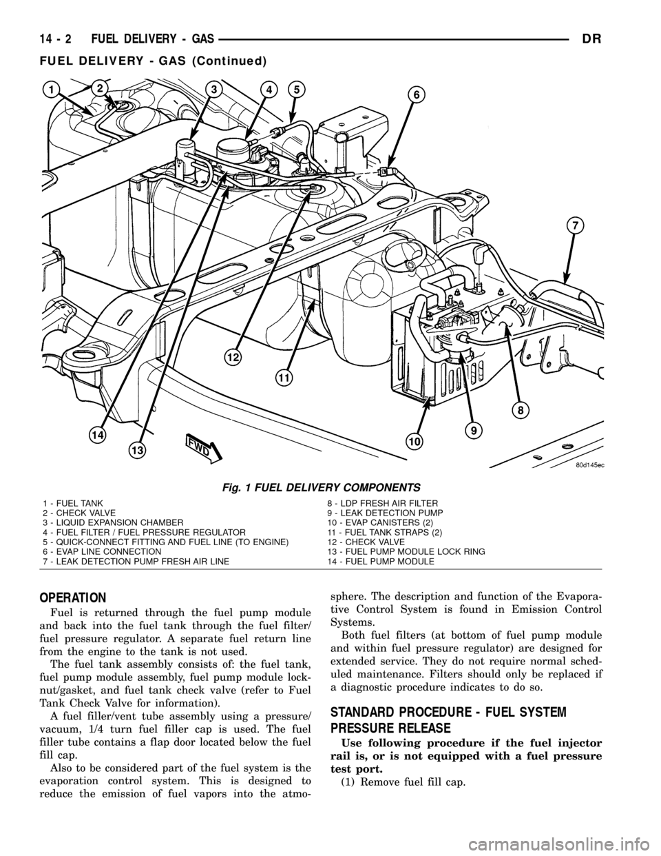
(Fig. 1).
DRFUEL SYSTEM 14 - 1
Page 1571 of 2627
OPERATION
Fuel is returned through the fuel pump module
and back into the fuel tank through the fuel filter/
fuel pressure regulator. A separate fuel return line
from the engine to the tank is not used.
The fuel tank assembly consists of: the fuel tank,
fuel pump module assembly, fuel pump module lock-
nut/gasket, and fuel tank check valve (refer to Fuel
Tank Check Valve for information).
A fuel filler/vent tube assembly using a pressure/
vacuum, 1/4 turn fuel filler cap is used. The fuel
filler tube contains a flap door located below the fuel
fill cap.
Also to be considered part of the fuel system is the
evaporation control system. This is designed to
reduce the emission of fuel vapors into the atmo-sphere. The description and function of the Evapora-
tive Control System is found in Emission Control
Systems.
Both fuel filters (at bottom of fuel pump module
and within fuel pressure regulator) are designed for
extended service. They do not require normal sched-
uled maintenance. Filters should only be replaced if
a diagnostic procedure indicates to do so.
STANDARD PROCEDURE - FUEL SYSTEM
PRESSURE RELEASE
Use following procedure if the fuel injector
rail is, or is not equipped with a fuel pressure
test port.
(1) Remove fuel fill cap.
Fig. 1 FUEL DELIVERY COMPONENTS
1 - FUEL TANK 8 - LDP FRESH AIR FILTER
2 - CHECK VALVE 9 - LEAK DETECTION PUMP
3 - LIQUID EXPANSION CHAMBER 10 - EVAP CANISTERS (2)
4 - FUEL FILTER / FUEL PRESSURE REGULATOR 11 - FUEL TANK STRAPS (2)
5 - QUICK-CONNECT FITTING AND FUEL LINE (TO ENGINE) 12 - CHECK VALVE
6 - EVAP LINE CONNECTION 13 - FUEL PUMP MODULE LOCK RING
7 - LEAK DETECTION PUMP FRESH AIR LINE 14 - FUEL PUMP MODULE
14 - 2 FUEL DELIVERY - GASDR
FUEL DELIVERY - GAS (Continued)
Page 1582 of 2627
REMOVAL
3.7L V-6
WARNING: THE FUEL SYSTEM IS UNDER CON-
STANT PRESSURE EVEN WITH ENGINE OFF.
BEFORE SERVICING FUEL RAIL, FUEL SYSTEM
PRESSURE MUST BE RELEASED.
CAUTION: The left and right fuel rails are replaced
as an assembly. Do not attempt to separate rail
halves at connector tubes (Fig. 18). Due to design
of tubes, it does not use any clamps. Never attempt
to install a clamping device of any kind to tubes.
When removing fuel rail assembly for any reason,
be careful not to bend or kink tubes.
(1) Remove fuel tank filler tube cap.
(2) Perform Fuel System Pressure Release Proce-
dure.
(3) Remove negative battery cable at battery.
(4) Remove air duct at throttle body air box.
(5) Remove air box at throttle body.
(6) Remove air resonator mounting bracket at
front of throttle body (2 bolts).
(7) Disconnect fuel line latch clip and fuel line at
fuel rail. A special tool will be necessary for fuel line
disconnection. Refer to Quick-Connect Fittings.
(8) Remove necessary vacuum lines at throttle
body.
(9) Disconnect electrical connectors at all 6 fuel
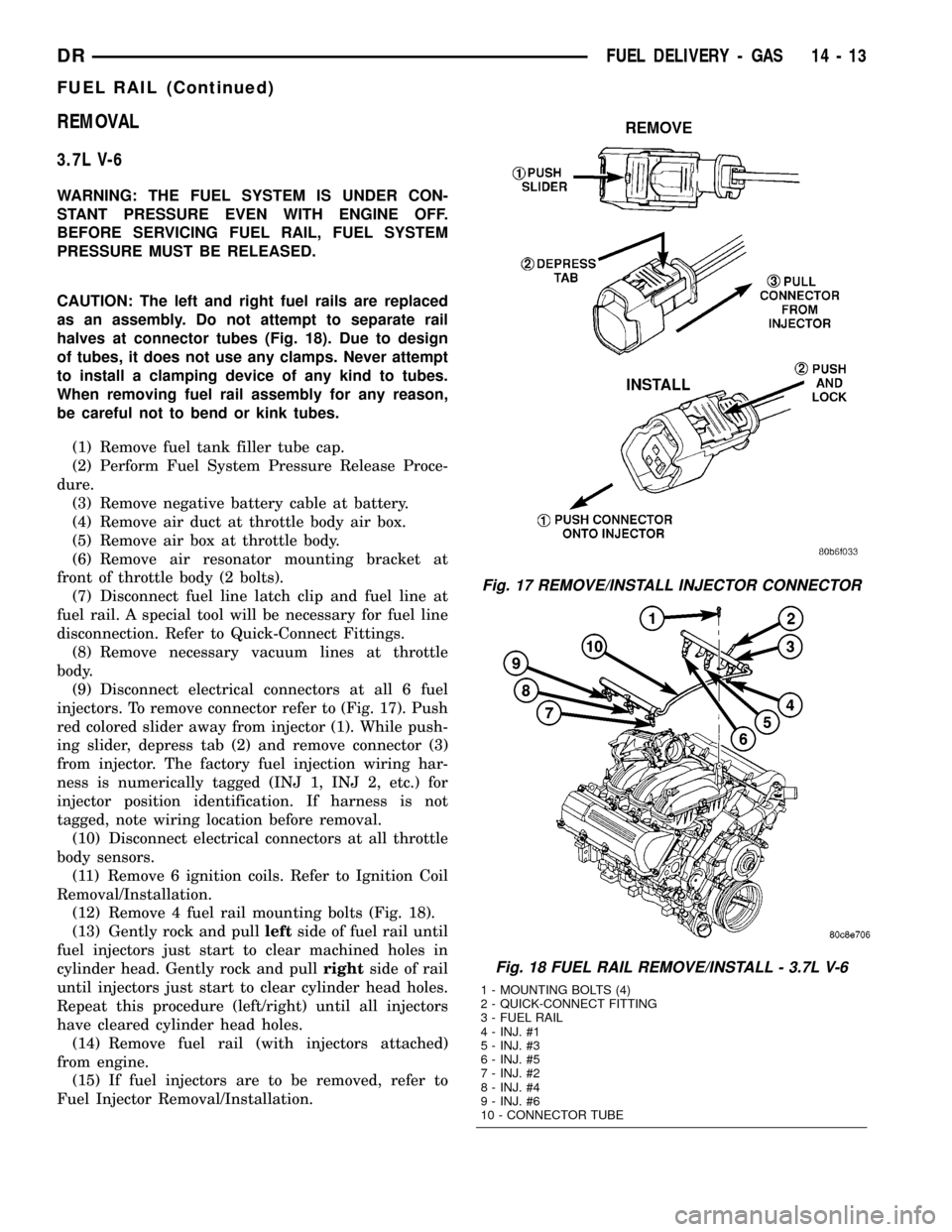
injectors. To remove connector refer to (Fig. 17). Push
red colored slider away from injector (1). While push-
ing slider, depress tab (2) and remove connector (3)
from injector. The factory fuel injection wiring har-
ness is numerically tagged (INJ 1, INJ 2, etc.) for
injector position identification. If harness is not
tagged, note wiring location before removal.
(10) Disconnect electrical connectors at all throttle
body sensors.
(11) Remove 6 ignition coils. Refer to Ignition Coil
Removal/Installation.
(12) Remove 4 fuel rail mounting bolts (Fig. 18).
(13) Gently rock and pullleftside of fuel rail until
fuel injectors just start to clear machined holes in
cylinder head. Gently rock and pullrightside of rail
until injectors just start to clear cylinder head holes.
Repeat this procedure (left/right) until all injectors
have cleared cylinder head holes.
(14) Remove fuel rail (with injectors attached)
from engine.
(15) If fuel injectors are to be removed, refer to
Fuel Injector Removal/Installation.
Fig. 17 REMOVE/INSTALL INJECTOR CONNECTOR
Fig. 18 FUEL RAIL REMOVE/INSTALL - 3.7L V-6
1 - MOUNTING BOLTS (4)
2 - QUICK-CONNECT FITTING
3 - FUEL RAIL
4 - INJ. #1
5 - INJ. #3
6 - INJ. #5
7 - INJ. #2
8 - INJ. #4
9 - INJ. #6
10 - CONNECTOR TUBE
DRFUEL DELIVERY - GAS 14 - 13
FUEL RAIL (Continued)
Page 1583 of 2627
4.7L V-8
WARNING: THE FUEL SYSTEM IS UNDER CON-
STANT PRESSURE EVEN WITH ENGINE OFF.
BEFORE SERVICING FUEL RAIL, FUEL SYSTEM
PRESSURE MUST BE RELEASED.
CAUTION: The left and right fuel rails are replaced
as an assembly. Do not attempt to separate rail
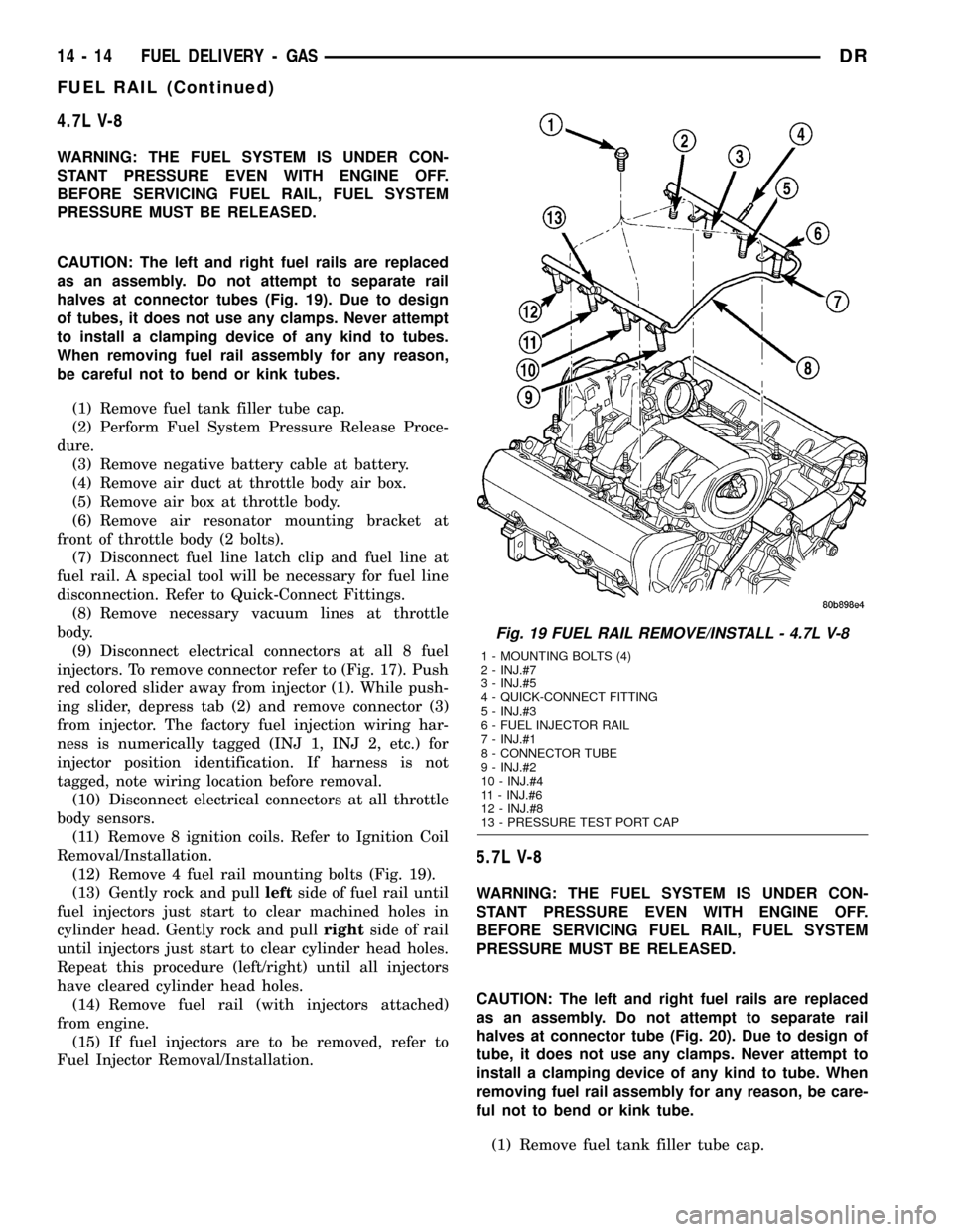
halves at connector tubes (Fig. 19). Due to design
of tubes, it does not use any clamps. Never attempt
to install a clamping device of any kind to tubes.
When removing fuel rail assembly for any reason,
be careful not to bend or kink tubes.
(1) Remove fuel tank filler tube cap.
(2) Perform Fuel System Pressure Release Proce-
dure.
(3) Remove negative battery cable at battery.
(4) Remove air duct at throttle body air box.
(5) Remove air box at throttle body.
(6) Remove air resonator mounting bracket at
front of throttle body (2 bolts).
(7) Disconnect fuel line latch clip and fuel line at
fuel rail. A special tool will be necessary for fuel line
disconnection. Refer to Quick-Connect Fittings.
(8) Remove necessary vacuum lines at throttle
body.
(9) Disconnect electrical connectors at all 8 fuel
injectors. To remove connector refer to (Fig. 17). Push
red colored slider away from injector (1). While push-
ing slider, depress tab (2) and remove connector (3)
from injector. The factory fuel injection wiring har-
ness is numerically tagged (INJ 1, INJ 2, etc.) for
injector position identification. If harness is not
tagged, note wiring location before removal.
(10) Disconnect electrical connectors at all throttle
body sensors.
(11) Remove 8 ignition coils. Refer to Ignition Coil
Removal/Installation.
(12) Remove 4 fuel rail mounting bolts (Fig. 19).
(13) Gently rock and pullleftside of fuel rail until
fuel injectors just start to clear machined holes in
cylinder head. Gently rock and pullrightside of rail
until injectors just start to clear cylinder head holes.
Repeat this procedure (left/right) until all injectors
have cleared cylinder head holes.
(14) Remove fuel rail (with injectors attached)
from engine.
(15) If fuel injectors are to be removed, refer to
Fuel Injector Removal/Installation.
5.7L V-8
WARNING: THE FUEL SYSTEM IS UNDER CON-
STANT PRESSURE EVEN WITH ENGINE OFF.
BEFORE SERVICING FUEL RAIL, FUEL SYSTEM
PRESSURE MUST BE RELEASED.
CAUTION: The left and right fuel rails are replaced
as an assembly. Do not attempt to separate rail
halves at connector tube (Fig. 20). Due to design of
tube, it does not use any clamps. Never attempt to
install a clamping device of any kind to tube. When
removing fuel rail assembly for any reason, be care-
ful not to bend or kink tube.
(1) Remove fuel tank filler tube cap.
Fig. 19 FUEL RAIL REMOVE/INSTALL - 4.7L V-8
1 - MOUNTING BOLTS (4)
2 - INJ.#7
3 - INJ.#5
4 - QUICK-CONNECT FITTING
5 - INJ.#3
6 - FUEL INJECTOR RAIL
7 - INJ.#1
8 - CONNECTOR TUBE
9 - INJ.#2
10 - INJ.#4
11 - INJ.#6
12 - INJ.#8
13 - PRESSURE TEST PORT CAP
14 - 14 FUEL DELIVERY - GASDR
FUEL RAIL (Continued)
Page 1586 of 2627
(15) Install air duct to air box.
(16) Connect battery cable to battery.
(17) Start engine and check for leaks.
5.7L V-8
(1) If fuel injectors are to be installed, refer to Fuel
Injector Removal/Installation.
(2) Clean out fuel injector machined bores in
intake manifold.
(3) Apply a small amount of engine oil to each fuel
injector o-ring. This will help in fuel rail installation.
(4) Position fuel rail/fuel injector assembly to
machined injector openings in intake manifold.
(5) Guide each injector into intake manifold. Be
careful not to tear injector o-rings.
(6) Pushrightside of fuel rail down until fuel
injectors have bottomed on shoulders. Pushleftfuel
rail down until injectors have bottomed on shoulders.
(7) Install 4 fuel rail holdown clamps and 4 mount-
ing bolts. Refer to Torque Specifications.
(8) Position spark plug cable tray and cable assem-
bly to intake manifold. Snap 4 cable tray retaining
clips into intake manifold.
(9) Install all cables to spark plugs and ignition
coils.
(10) Connect electrical connector to throttle body.
(11) Install electrical connectors to all 8 ignition
coils. Refer to Ignition Coil Removal/Installation.
(12) Connect electrical connector to throttle body.
(13) Connect electrical connectors at all fuel injec-
tors. To install connector, refer to (Fig. 17). Push con-
nector onto injector (1) and then push and lock red
colored slider (2). Verify connector is locked to injec-
tor by lightly tugging on connector.
(14) Connect fuel line latch clip and fuel line to
fuel rail. Refer to Quick-Connect Fittings.
(15) Install air resonator to throttle body (2 bolts).
(16) Install flexible air duct to air box.
(17) Connect battery cable to battery.
(18) Start engine and check for leaks.
FUEL TANK
DESCRIPTION
The fuel tank is constructed of a plastic material.
Its main functions are for fuel storage and for place-
ment of the fuel pump module, and (if equipped) cer-
tain ORVR components.
OPERATION
All models pass a full 360 degree rollover test
without fuel leakage. To accomplish this, fuel and
vapor flow controls are required for all fuel tank con-
nections.Two check (control) valves are mounted into the
top of the fuel tank. Refer to Fuel Tank Check Valve
for additional information.
An evaporation control system is connected to the
fuel tank to reduce emissions of fuel vapors into the
atmosphere. When fuel evaporates from the fuel
tank, vapors pass through vent hoses or tubes to a
charcoal canister where they are temporarily held.
When the engine is running, the vapors are drawn
into the intake manifold. Certain models are also
equipped with a self-diagnosing system using a Leak
Detection Pump (LDP) and/or an On-Board Refueling
Vapor Recovery (ORVR) system. Refer to Emission
Control System for additional information.
REMOVAL- EXCEPT DIESEL
Fuel Tank Draining
WARNING: THE FUEL SYSTEM MAY BE UNDER
CONSTANT FUEL PRESSURE EVEN WITH THE
ENGINE OFF. THIS PRESSURE MUST BE
RELEASED BEFORE SERVICING FUEL TANK.
Two different procedures may be used to drain fuel
tank: through the fuel fill fitting on tank, or using
the DRBtscan tool. Due to a one-way check valve
installed into the fuel fill opening fitting at the tank,
the tank cannot be drained conventionally at the fill
cap.
The quickest draining procedure involves removing
the rubber fuel fill hose.
As an alternative procedure, the electric fuel pump
may be activated allowing tank to be drained at fuel
rail connection. Refer to DRB scan tool for fuel pump
activation procedures. Before disconnecting fuel line
at fuel rail, release fuel pressure. Refer to the Fuel
System Pressure Release Procedure for procedures.
Attach end of special test hose tool number 6541,
6539, 6631 or 6923 at fuel rail disconnection (tool
number will depend on model and/or engine applica-
tion). Position opposite end of this hose tool to an
approved gasoline draining station. Activate fuel
pump and drain tank until empty.
If electric fuel pump is not operating, fuel must be
drained through fuel fill fitting at tank. Refer to fol-
lowing procedures.
(1) Release fuel system pressure.
(2) Raise vehicle.
(3) Thoroughly clean area around fuel fill fitting
and rubber fuel fill hose at tank.
(4) If vehicle is equipped with 4 doors and a 6 foot
(short) box, remove left-rear tire/wheel.
(5) Loosen clamp (Fig. 23) and disconnect rubber
fuel fill hose at tank fitting. Using an approved gas
holding tank, drain fuel tank through this fitting.
DRFUEL DELIVERY - GAS 14 - 17
FUEL RAIL (Continued)
Page 1616 of 2627
STANDARD PROCEDURE
STANDARD PROCEDURES - WATER DRAINING
AT FUEL FILTER
Refer to Fuel Filter/Water Separator removal/in-
stallation for procedures.
STANDARD PROCEDURES - CLEANING FUEL
SYSTEM PARTS
CAUTION: Cleanliness cannot be overemphasized
when handling or replacing diesel fuel system com-
ponents. This especially includes the fuel injectors,
high-pressure fuel lines and fuel injection pump.
Very tight tolerances are used with these parts. Dirt
contamination could cause rapid part wear and pos-
sible plugging of fuel injector nozzle tip holes. This
in turn could lead to possible engine misfire.
Always wash/clean any fuel system component
thoroughly before disassembly and then air dry.
Cap or cover any open part after disassembly.
Before assembly, examine each part for dirt, grease
or other contaminants and clean if necessary. When
installing new parts, lubricate them with clean
engine oil or clean diesel fuel only.
STANDARD PROCEDURE - FUEL SYSTEM
PRIMING
A certain amount of air becomes trapped in the
fuel system when fuel system components on the
supply and/or high-pressure side are serviced or
replaced. Fuel system priming is accomplished using
the electric fuel transfer (lift) pump.
Servicing or replacing fuel system components will
not require fuel system priming.
The fuel transfer (lift) pump is self-priming: When
the key is first turned on (without cranking engine),
the pump operates for approximately 1 to 2 second
and then shuts off. The pump will also operate for up
to 25 seconds after the starter is quickly engaged,
and then disengaged without allowing the engine to
start. The pump shuts off immediately if the key is
on and the engine stops running.
(1) Turn key to CRANK position and quickly
release key to ON position before engine starts. This
will operate fuel transfer pump for approximately 25
seconds.
(2) Crank engine. If the engine does not start after
25 seconds, turn key OFF. Repeat previous step until
engine starts.
(3) Fuel system priming is now completed.
(4) Attempt to start engine. If engine will not
start, proceed to following steps.When engine does
start, it may run erratically and be noisy for a
few minutes. This is a normal condition.
CAUTION: Do not engage the starter motor for more
than 30 seconds at a time. Allow two minutes
between cranking intervals.
(5) Perform previous fuel priming procedure steps
using fuel transfer pump. Be sure fuel is present at
fuel tank.
(6) Crank the engine for 30 seconds at a time to
allow fuel system to prime.
WARNING: THE FUEL INJECTION PUMP SUPPLIES
EXTREMELY HIGH FUEL PRESSURE TO EACH INDI-
VIDUAL INJECTOR THROUGH THE HIGH-PRES-
SURE LINES. FUEL UNDER THIS AMOUNT OF
PRESSURE CAN PENETRATE THE SKIN AND
CAUSE PERSONAL INJURY. WEAR SAFETY GOG-
GLES AND ADEQUATE PROTECTIVE CLOTHING.
DO NOT LOOSEN FUEL FITTINGS WHILE ENGINE
IS RUNNING.
WARNING: ENGINE MAY START WHILE CRANKING
STARTER MOTOR.
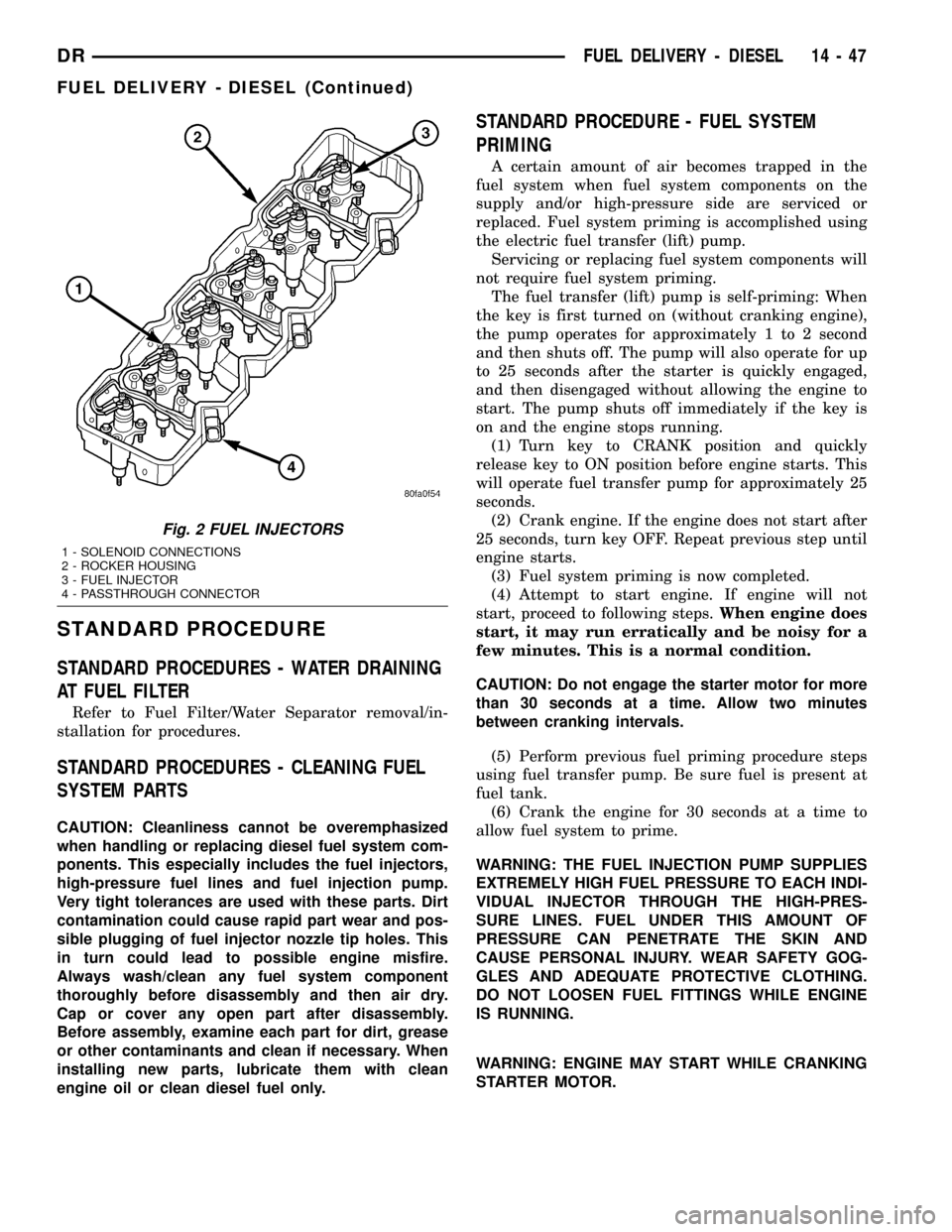
Fig. 2 FUEL INJECTORS
1 - SOLENOID CONNECTIONS
2 - ROCKER HOUSING
3 - FUEL INJECTOR
4 - PASSTHROUGH CONNECTOR
DRFUEL DELIVERY - DIESEL 14 - 47
FUEL DELIVERY - DIESEL (Continued)
Page 2574 of 2627
FUEL FILLER CAP
DESCRIPTION
The plastic fuel tank filler tube cap is threaded
onto the end of the fuel fill tube. Certain models are
equipped with a 1/4 turn cap.
OPERATION
The loss of any fuel or vapor out of fuel filler tube
is prevented by the use of a pressure-vacuum fuel fill
cap. Relief valves inside the cap will release fuel tank
pressure at predetermined pressures. Fuel tank vac-
uum will also be released at predetermined values.
This cap must be replaced by a similar unit if
replacement is necessary. This is in order for the sys-
tem to remain effective.
CAUTION: Remove fill cap before servicing any fuel
system component to relieve tank pressure. If
equipped with a Leak Detection Pump (LDP), or
NVLD system, the cap must be tightened securely.
If cap is left loose, a Diagnostic Trouble Code (DTC)
may be set.
REMOVAL
REMOVAL/INSTALLATION
If replacement of the 1/4 turn fuel tank filler tube
cap is necessary, it must be replaced with an identi-
cal cap to be sure of correct system operation.
CAUTION: Remove the fuel tank filler tube cap to
relieve fuel tank pressure. The cap must be
removed prior to disconnecting any fuel system
component or before draining the fuel tank.
LEAK DETECTION PUMP
DESCRIPTION
Vehicles equipped with JTEC engine control mod-
ules use a leak detection pump. Vehicles equipped
with NGC engine control modules use an NVLD
pump. Refer to Natural Vacuum - Leak Detection
(NVLD) for additional information.
The evaporative emission system is designed to
prevent the escape of fuel vapors from the fuel sys-
tem (Fig. 4). Leaks in the system, even small ones,
can allow fuel vapors to escape into the atmosphere.
Government regulations require onboard testing to
make sure that the evaporative (EVAP) system is
functioning properly. The leak detection system tests
for EVAP system leaks and blockage. It also performs
self-diagnostics. During self-diagnostics, the Power-
train Control Module (PCM) first checks the Leak
Detection Pump (LDP) for electrical and mechanical
faults. If the first checks pass, the PCM then uses
the LDP to seal the vent valve and pump air into the
system to pressurize it. If a leak is present, the PCM
will continue pumping the LDP to replace the air
that leaks out. The PCM determines the size of the
leak based on how fast/long it must pump the LDP
as it tries to maintain pressure in the system.
EVAP LEAK DETECTION SYSTEM COMPONENTS
Service Port: Used with special tools like the Miller
Evaporative Emissions Leak Detector (EELD) to test
for leaks in the system.
EVAP Purge Solenoid: The PCM uses the EVAP
purge solenoid to control purging of excess fuel
vapors stored in the EVAP canister. It remains closed
during leak testing to prevent loss of pressure.
EVAP Canister: The EVAP canister stores fuel
vapors from the fuel tank for purging.
EVAP Purge Orifice: Limits purge volume.
EVAP System Air Filter: Provides air to the LDP
for pressurizing the system. It filters out dirt while
allowing a vent to atmosphere for the EVAP system.
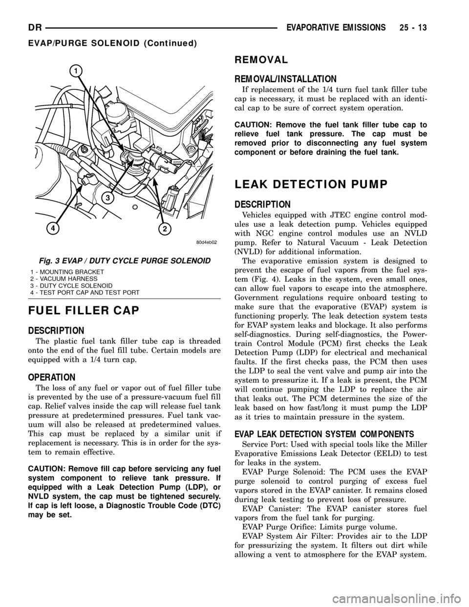
Fig. 3 EVAP / DUTY CYCLE PURGE SOLENOID
1 - MOUNTING BRACKET
2 - VACUUM HARNESS
3 - DUTY CYCLE SOLENOID
4 - TEST PORT CAP AND TEST PORT
DREVAPORATIVE EMISSIONS 25 - 13
EVAP/PURGE SOLENOID (Continued)