1998 BMW 540i 240
[x] Cancel search: 240Page 3 of 1002

Downloaded from www.Manualslib.com manuals search engine
YOU are now in Volume I
I
Foreword ................... .. ........................................................................\
.......... v
Index
........................ .. ................................................................ rear of manual
General, 001 General Warnings and Cautions 002 Vehicle Identification and VIN Decoder
Maintenance OiO 020 Maintenance
Engine
100 Engine-General 110 Engine Removal and Installation
113 Cylinder Head Removal and
Installation
116 Cyiinder Head and Valvetrain 117 Camshaft Timing Chain
119 Lubrication System
200 Transmission-General
2 Transmission 210 clutch 230 ManualTransmission
I20 Ignition System
121 Battery, Starter, Alternator
130 Fuel Injection
160 Fuel Tank and Fuel Pump 170 Radiator and Cooling System
180 Exhaust System
240 Automatic Transmission
250 Gearshift Linkage 260 Driveshaft
Suspension, 300 Suspension, Steering and 330 Rear Suspension
Brakes-General 331 Final Drive
Steering and No Front Suspension 340 Brakes
320 Steering and Wheel Alignment
400 Body-General
410 Fenders, Engine Hood 411 Doors
412 Trunk Lid, Tailgate
510 Exterior Trim, Bumpers 512 Door Windows
Equipment 513 Interior Trim
7
Equipment and 720 seat Belts
Accessories 721 Airbag System (SRS)
OBD On-Board Diagnostics
. ............ ..
515 Central Lociting and
Anti-Theft
520 Seats 540 Sunroof
.................................................................... Foreword .............................. .. v
Index ................... .. ................................................................ rear of manual
Electrical
6 system
600 Electrical System-General 620 Instruments
610 Electrical Comoonent Locations 630 Liohts
611 wipers and washers 612 Switches eati in^ and Air Conditioning
Radio
. ........... ........ .........................
Electrical Wiring Diagrams
Page 30 of 1002

Downloaded from www.Manualslib.com manuals search engine
01 0-20
General
more information on the Check Engine Light and the on-
board diagnostic system.
Towing
The cars covered by this manual should be towed with a tow
truck using wheel lift or flat bed equipment. Do not tow the car
on all four wheels except
forvery short distances to move it to
a safe place.
CA U JION-
Do not tow with sling-type equipment The front spoilers and
b~m~er covers may sustain damage.
4 To access threaded towing eye socltet, pry open trim on front
or rear bumper.
NOJE-
A towing eye is provided in the luggage compartment tool lcit.
The towing eye can be screwed into the front or rear bumper.
4 Install towing eye into threaded hole.
- Standard transmission: Do not tow with rear wheels on
ground unless absolutely necessary.
- Automatic transmission: Have rear wheels placed on dollies,
or use flat bed truck. Use towing eye for winching vehicle on
flat bed.
CAUTION-
Automatic transmission fluid (ATF) does not circulate when
I the car is towed. Severe transmission damage may result.
NOTE-
Be sure transrnission fluid has been topped off before
starting tow.
Always tow car with transrnission lever in
N (neutral).
. ATF draining and filling is covered in 240 Automatic
Transmission.
Be sure to read the filling and draining pro.
cedure, as special service equipment is required to
checlc
the fluid level.
Page 62 of 1002

Downloaded from www.Manualslib.com manuals search engine
020-30
Maintenance
fluid use and the most-up-to-date information regarding
transmission operating fluids.
The automatic transmission is not equipped with a dipstick.
Therefore, checking the ATF level is an involved procedure
which includes measuring and maintaining a specified ATF
temperature during the checking procedure.
For more complete
ATF service information, including
checking
ATF level and ATF filter replacement procedures,
see
240 Automatic Transmission.
Transmission service, manual
Manual transmission service consists of inspecting for leaks
and checking the fluid. Evidence of transmission leaks is
like-
ly to be seen around the driveshaft mounting flange and at the
bottom of the bellhousing.
NOTE-
For more information on identifying oil
leaks and their
causes, see 230 Manual Transmission and210 Clutch.
Transmission fluid, checking and filling
(manual transmission)
Tne manual transmss'on inslalleo 'n rne E39 models s f;lled
with a special liierime iluid (ivlTF-LT-I). oi. ordinarily
does
not need to be changed.
< Check manual transmission oil level at transmission filler plug
(A). Make sure car is on level surface.
NOTE- Transmission fluid level
checking and replacement
procedures are covered in 230 Manual Transmission.
Wheels, aligning
BMW recommends checking the front and rear alignment
once a year and whenever new tires are installed.
NOTE-
See 320 Steering and Wheel Alignment for a more detailed
discussion of alignment requirements and specifications.
Page 74 of 1002

Downloaded from www.Manualslib.com manuals search engine
I Engine Removal and Installation
Engine removal and installation are covered in this repail
group.
See 100 Engine-General for engine identification details
and engine codes.
Transmission removal is required for all models before the
engine can be removed. This is best accomplished with the
car raised on an automotive lift. For additional procedures re-
quired during engine removal, refer to the following repair
groups:
020 Maintenance
0 121 Battery, Alternator, Starter
170 Radiator and Cooling System
180 Exhaust System
4 230 Manual Transmission
0 240 Automatic Transmission
410 Fenders, Engine Hood
Special tools
Some special tools are required for engine removal and in-
stallation. Be sure to have the necessary equipment on hand
before starting the job.
Engine lifting tool
(Tool No. BMW
11 0 000)
4 Cooling fan counterhold tool
(Tool No. BMW
11 5 030)
< Cool~ng fan wrench
(Tool No. BMW
11 5 040)
Page 85 of 1002

Downloaded from www.Manualslib.com manuals search engine
Engine Removal and Installation
4 Working at E-box at right rear of engine compartment:
Disconnect engine electrical harness connectors
(arrows).
Lift off harness looms and lay over engine.
- Remove polyribbed drive belts. Mark direction of rotation if
belts will be reused. See 020 Maintenance.
- Remove exhaust system and transmission from car. See 180
Exhaust System, 230 Manual Transmission or 240 Auto-
matic Transmission.
NOJE-
Detach automatic transmission cooler lines from radiator, re-
move brackets holding lines to side of engine, andstore lines
in a clean environment.
- Remove power steering pump:
If necessary, remove steering pump pulley.
Remove front and rear pump mounting bolts.
Suspend pump from body using stiff wire.
4 Remove A/C compressor mounting bolts (arrows) and AIC
compressor from its mounting bracketwithoutdisconnecting,
distorting, or deforming any refrigerant lines. Suspend from
body using stiff wire.
4 If applicable, remove secondary air pump:
Remove hose at one-way valve
(A).
Remove bolts at support bracket on strut tower (arrows).
- Disconnect electrical harness from bottom of secondary
air pump.
Remove bracket from strut tower.
Page 92 of 1002

Downloaded from www.Manualslib.com manuals search engine
11 0-20
Engine Removal and Installation
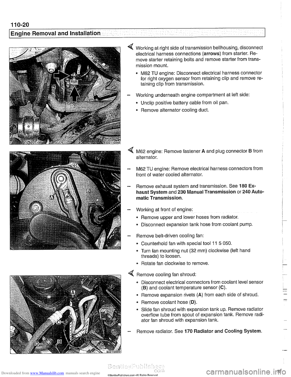
Working at right side of transmission bellhousing, disconnect
electrical harness connections (arrows) from starter. Re-
move starter retaining bolts and remove starter from trans-
mission mount.
M62 TU engine: Disconnect electrical harness connector
for right oxygen sensor from retaining clip and remove re-
taining clip from transmission.
- Working underneath engine compartment at left side:
Unclip positive battery cable from oil pan.
. Remove alternator cooling duct.
4 M62 engine: Remove fastener A and plug connector B from
alternator.
- M62 TU engine: Remove electrical harness connectors from
front of water cooled alternator.
- Remove exhaust system and transmission. See 180 Ex-
haust System and 230 Manual Transmission or 240 Auto-
matic Transmission.
- Working at front of engine:
Remove upper and lower hoses from radiator.
D~sconnect expansion tank hose from coolant pump.
- Remove belt-driven cooling fan:
Counterhold fan with special tool
11 5 050.
Turn fan mounting nut (32 mm) clockwise (left hand
threads) to loosen.
Rotate fan clockwise to remove.
Remove cooling fan shroud:
Disconnect electrical connectors from coolant level sensor
(B) and coolant temperature sensor (C).
. Remove expansion rivets (A) from each side of shroud
Remove coolant hose
(D).
Slide fan shroud with expansion tank up. Remove radiator
overflow tube from spout of expansion tank. Remove radi-
ator fan shroud with expansion tank.
Remove radiator. See
170 Radiator and Cooling System.
Page 97 of 1002

Downloaded from www.Manualslib.com manuals search engine
11 3-3
Cylinder Head Removal and Installation
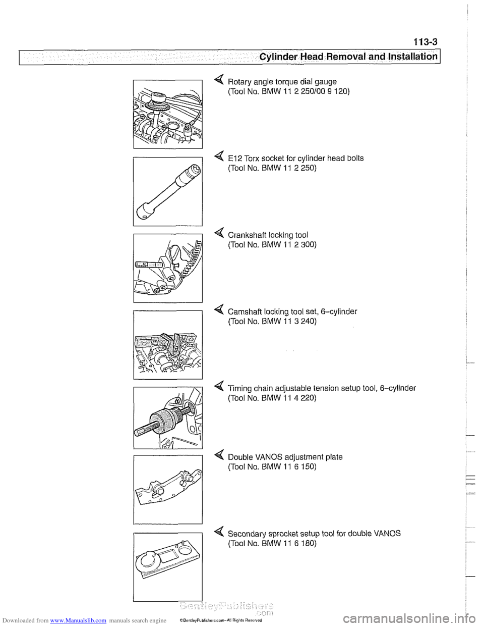
4 Rotary angle torque dial gauge
(Tool No. BMW
11 2 250100 9 120)
4 El2 Torx socket for cylinder head bolts
(Tool No.
BMW 11 2 250)
4 Crankshaft loclting tool
(Tool No.
BMW 11 2 300)
4 Camshaft locking tool set, 6-cylinder
/I (Tool No, BMW 11 3 240)
< Timing chain adjustable tension setup tool, 6-cylinder
(Tool No.
BMW 11 4 220)
>
Double VANOS adiustment date
4 Secondary sprocket setup tool for double VANOS
(Tool No. BMW
11 6 180)
Page 108 of 1002

Downloaded from www.Manualslib.com manuals search engine
11 3-1 4
Cylinder Head Removal and Installation
4 Secure camshafts in TDC position using BMW special tool
set
11 3 240.
4 Remove access plugs from VANOS control unit in front of
exhaust camshaft sprocket.
Remove
4 bolts (arrows) from exhaust camshaft sprocket
(Torx E10).
CAUTION-
Hold the camshaft stationary (at hex on camshaft) when loos-
eninq or tiqhteninq sprocl(et mounting fasteners. r
Press down on secondary chain tensioner and lock into place
using
BMW special tool 11 3 292 or a similar size pin.
NOTE-
Some tensioners may have a single hole for special tool.
Remove secondary chain tensioner.
Disconnect harness connector and oil line fitting from bottom
of VANOS control unit.
NOTE-
Wrap the VANOS oil line fitting with a shop rag to absorb
leaking oil.
Remove VANOS control unit mounting nuts and bolt at front
of cylinder head.