Page 138 of 1002
Downloaded from www.Manualslib.com manuals search engine
11 3-44
I Cylinder Head Removal and Installation
4 Secure camshafts in TDC position using BMW special tool
set
11 3 240.
4 In necessary, turn camshaft slightly so that special tools are
squarely seated on cylinder head.
4 Lift timing chain and hold under tension.
Page 141 of 1002
![BMW 540i 1998 E39 Workshop Manual Downloaded from www.Manualslib.com manuals search engine
Cylinder Head Removal - an-]
Fit thrust spacer (A) to intake camshaft (B) and tighten down
with threaded locating studs. Place longer th](/manual-img/1/2822/w960_2822-140.png "BMW 540i 1998 E39 Workshop Manual Downloaded from www.Manualslib.com manuals search engine
Cylinder Head Removal - an-]
Fit thrust spacer (A) to intake camshaft (B) and tighten down
with threaded locating studs. Place longer th")
Downloaded from www.Manualslib.com manuals search engine
Cylinder Head Removal - an-]
Fit thrust spacer (A) to intake camshaft (B) and tighten down
with threaded locating studs. Place longer threaded end of
studs into camshaft
(arrows).
Tightening torque
Impulse
wheel studs to intake camshaft) 20 Nm (15 ft-lb)
Fit primary sprocket to primary timing chain and install on ex-
haust camshaft so that pointer on sprocket
(arrow) lines up
with cylinder head sealing surface.
4 Insert BMW special tool 11 4 220 into timing chain tensioner
bore and bring center spindle into contact with tensioning rail.
Tighten until slack is removed, but do not pretension timing
chain.
NOTE-
BMW special tool 11 4 220 is an adjustable primary chain
tensioner and simulates the function of the tensioner.
- Rechecic arrow on primary sprocket is aligned with upper
edge of cylinder head. Reposition sprocket if necessary.
Insert and tighten down threaded locating studs
(arrows) in
end of exhaust camshaft. Note installed position of studs.
Tightening torques Exhaust camshaft locating stud
20 Nm (15 ft-lb)
Page 142 of 1002
Downloaded from www.Manualslib.com manuals search engine
I Cvlinder Head Removal and Installation
4 Install secondary chain tensioner on cylinder head (arrows).
Keep tensioner compressed using BMW special tool 11 3
291 or suitable pin.
< Install exhaust camshaft splined sleeve. Confirm that gap in
sleeve splines aligns with corresponding gap in
camshaft
splines (arrows).
Slide splined shaft onto exhaust camshaft. Be sure that locat-
ing tooth of shaft fits into spline gaps of camshaft and splined
sleeve
(arrows).
- Push splined shaft in further to rotate splined sleeve until the
three threaded holes in primary chain sprocket are centered
in the small slots of the splined sleeve.
4 Place intake and exhaust sprockets in BMW special tool 11 6
180. Position spline gap on intake sprocket (arrow) as shown
and place secondary chain on sprockets.
Page 145 of 1002
Downloaded from www.Manualslib.com manuals search engine
113-51
Cylinder Head Removal and Installation
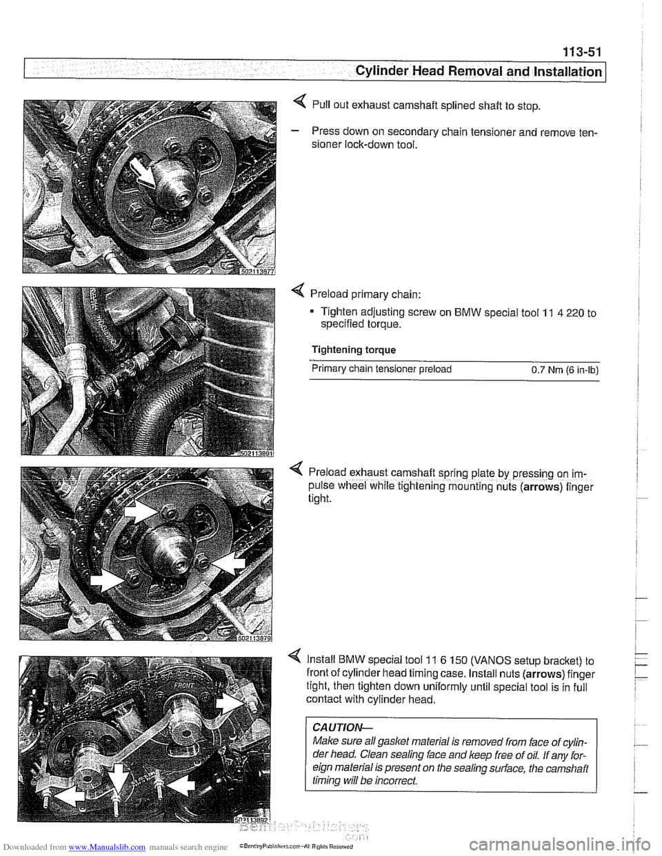
< Pull out exhaust camshaft splined shaft to stop.
- Press down on secondary chain tensioner and remove ten-
sioner lock-down tool.
Preload primary chain:
Tighten adjusting screw on
BMW special tool 11 4 220 to
specified torque.
Tightening torque
Primary chain tensioner preload
0.7 Nrn (6 in-lb)
< Preload exhaust camshaft sprrng plate by pressing on im-
pulse wheel while tightening mounting nuts (arrows) finger
tight.
Install BMW special tool 11 6 150 (VANOS setup bracket) to
front of cylinder head timing case. Install nuts (arrows) finger
tight, then tighten down uniformly until special tool is in full
contact with cylinder head.
CAUTION-
Make sure all gasket material is removed from face of cylin-
der head. Clean sealing
face and keep free of oil. If any for-
eign material is present on the sealing
sudace, the camshait
timina will be incorrect.
Page 146 of 1002

Downloaded from www.Manualslib.com manuals search engine
. .- --
Cylinder Head Removal and Installation
Secure camshaft sprockets and impulse wheels:
Tighten mounting screws
(A) on exhaust camshaft impulse
wheel to approx.
5 Nm (44 in-lb).
Tighten mounting nuts
(8) on exhaust and intake sprocket
assemblies to approx.
5 Nm (44 in-lb).
Torque down mounting screws (A) and nuts (B) to final
specifications.
Tightening torques
sprocket assembly to camshaft
initial torque
5 Nm (44 in-lb)
Sprocket assembly
wheel to camshaft
M7 torx screws (A) 20 Nm (15 ft-lb)
M6 mounting nuts (5) 10 Nm (8 ft-lb)
- Remove crankshaft locking tool from transmission bell hous-
ing so that crankshaft is no longer secured in
TDC position.
- Remove camshaft locking tools from cylinder head.
4 Turn engine over twice in direction of rotation until cylinder 1
intake and exhaust camshaft lobes (arrows) face each other.
- Secure crankshaft in TDC position with BMW special tool 11
2 300.
4 Place BMW special tool set 11 3 240 over camshafts and
measure clearances.
CAUTION-
- If the exhaust side of the tool (A) is not flush with tlie head,
camshaft timing is incorrect Reset camshaft timing as de-
scribed in
117 Camshaft Timing Chain.
* Due to flexible sprocket design, VANOS unit tolerances
and play in the VANOS splines, when the camshaft tim-
ing is set correctly, the intake side of special tool
11 3
240 (6) may be up to 1 mm (0.04 in.) above the surface
of the cylinder head. This is normal. Reassemble en-
gine.
Othe~lise, reset camshaft timing as described in
11 7 Camshaft Timing Chain.
- Remove BMW special tool 11 6 150 from front of cylinder
head.
Page 154 of 1002

Downloaded from www.Manualslib.com manuals search engine
1 13-60
Cylinder Head Removal and Installation
Label and disconnect fuel lines from fuel rail by pressing lock-
ing sleeves
(arrows) in to release lines.
NOTE-
BMW uses three styles of fuel line connections; a single use
clamp; a locking fitting that uses special tool
16 1 050 to re-
lease; and a quick release sleeve
(arrow) that disconnects
the line when depressed.
CAUTION-
Fuel may be expelled under pressure. Do not smoke or
work near heaters or other fire hazards. Keep a fire
exfin-
guisher handy Before disconnecting fuel hoses, wrap a
cloth around fuel hoses to absorb
leaking fuel. Plug all
I ooen fuel lines. I
Always unscrew fuel tank cap to release pressure in
tank before
removinq fuel lines.
Cap fuel lines and fuel rail inlets.
Disconnect vacuum lines
(A, B and C) from rear of intake
manifold.
Working at rear of intake manifold, disconnect crankcase
ventilation valve from pipe by prying up on lock
(A) and slid-
ing tube forward
(B).
Page 160 of 1002

Downloaded from www.Manualslib.com manuals search engine
. .- --
I Cylinder Head Removal and Installation
- Evaluate cylinder head as described in 116 Cylinder head
and valvetrain.
Left cylinder head, installing, M62 engine
- Clean cylinder head and block sealing surfaces of gasket
debris, making sure no debris drops into coolant or oil pas-
sages.
- Clean cylinder head bolt holes and check condition of
threads.
< Check cylinder head locator sleeves (arrows) for damage.
If the cylinder head has been machined, a special
0.3 mm
thicker gasket should be installed. The thicker gasket is avail-
able through an authorized
BMW dealer and should be
marked accordingly.
- Place new cylinder head gasket over locating sleeve on
block.
The word
"OBEN" or "TOP" (arrow) printed on the gasket,
must face up.
Set lefl side cylinder head in position on cylinder block while
pressing oil separator outward.
CAUJION-
Male sure the crankshaft, which had been rotated approxi-
mately
45" opposite the direction of engine rotation from
TDC, is still in thatposition before installing the cylinder head.
All pistons must be out of
TDCposition to prevent valvelpis-
ton contact.
- Install new cylinder head bolts and washers finger tight. Be
sure not to remove coating from new cylinder head bolts.
4 Tighten cylinder head bolts in correct sequence (1-10) to
stage
1 torque values.
Page 162 of 1002
Downloaded from www.Manualslib.com manuals search engine
11 3-68
Cylinder Head Removal and Installation
< Using BMW special tool 11 3 430, or a 27 mm open-ended
wrench, rotate camshafts to cylinder 1
TDC position (until
markings point upwards).
I I < Install camshaft locltina tool set (BMW soecial tool set 11 2
440) on right cylinder head (cylinders 1-4). Fit on cylinde~
head without gaps.
Install
camshaft locking tool set (BMW special tool set 11 2
440) on left cylinder head (cylinder head 5-8). Fit on cylinder
head without gaps.
4 Using crankshaft center bolt, rotate engine clockwise from
the
45" mark to TDC position (OIT aligns with casting mark
on cylinder block).