1998 BMW 540i Start
[x] Cancel search: StartPage 52 of 1002

Downloaded from www.Manualslib.com manuals search engine
Maintenance
continue to operate as designed. Extending the replacement
interval may void the emission control warranty coverage.
See
180 Exhaust System for information on replacing the
oxygen sensors.
Tightening torque
Oxvoen sensor to exhaust
manifold 50 Nrn (37 ft-lb)
NOTE-
A special soclet for replacing the oxygen sensor is available
from most automotive parts stores. The soclet has
a groove
cut down one side to allow the sensor to be installed without
damaging the wire harness.
Power steering fluid, checking level
The power steering system is permanently filled and does not
have a drain. Routinely adding ATF is not required unless the
system is leaking.
4 To check power steering fluid level in fluid reservoir:
Park car on level ground with engine off.
Level is correct
if it is between MlN and MAX marks on
dipstick.
If level is below
MlN mark, add fluid to reservoir to bring
level up.
* Hand-tighten reservoir cap.
Power steering fluid
Dexron
1iiO ATF or equivalent
Spark plugs
E39 models through model year 1998 were equipped with
spark plugs with two electrodes. These are gapped to
0.7 mm
(0.028 in) by the manufacturer and are not adjustable.
Starting with 1999 models, long life spark plugs with
3 or four
electrodes were used. These can be retroactively fitted to
earlier
models. The recommended spark plug replacement
interval
forthese is 100,000 miles.The electrode gap in these
spark plugs is not adjustable.
Spark plug applications
M52 Bosch FBLDCR
M52 TU, M54 Bosch FGR7DQP or NGK BKRBEQUP
M62 to 7/97 Bosch F7LDCR or NGK BKR6EK
M62 from 7/97 Bosch F9LDCR
M62 TU Bosch FGR7DQP or NGK BKRGEQUP
Page 54 of 1002

Downloaded from www.Manualslib.com manuals search engine
020-22 Maintenance
1
- Installation is reverse of removal, bearing in mind the
following:
Lightly lubricate new
spark plug threads with
copper-based anti-seize compound.
Thread plugs into cylinder head by hand to prevent
cross-threading.
. Be sure to reinstall and tighten coil grounds.
Tightening torque Spark plug
to cylinder head 25 Nm (18 It-lb)
Interior ventilation microfilter, replacing
Two interior ventilation microfilters are used, one on each
side of the engine compartment at the fire wall.
< To replace the microfilter, unclip the wire fastener and
remove the cover.
Lift out the filter, and replace. Left side shown; right is
similar.
Replace cover and clip wire fastener to retain cover.
Battery, checking, cleaning, and replacing
The battery Is located in the right side of the luggage compart-
ment. Simple maintenance of the battery and its terminal
connections will ensure maximum starting periormance,
especially in winter when colder temperatures reduce battery
power.
Battery cables should be tight. The terminals, cable clamps
and battery case should be free of the white deposits that
indicate corrosion and acid salts. Even a thin layer of dust
containing conductive acid salts can cause battery discharge.
Page 56 of 1002

Downloaded from www.Manualslib.com manuals search engine
020-24
Maintenance
tions. In general, replacement batteries should always be
rated equal or higher than the original battery.
The battery is held in place by a single hand screw and plate.
A secure battery hold-down is important in order to prevent
vibrations and road shoclt from damaging the battery.
CAUTION-
Prior to disconnecting the baitem read the battery discon-
nection cautions given in
001 General Cautions and
Warnings.
NOTE-
Always disconnect the negative (-) cable first, and connect
it last. While changing the battery, clean away any corro-
sion in or around the battery tray
More battery and charging system information is in 121
Battery, Alternator, Starter.
Brake fluid, replacing
Brake fluid absorbs moisture easily, and moisture in the fluid
affects bralte performance and reliability. This is why
BMW
strictly recommends replacing the bralte fluid every two
years. When replacing or adding bralte fluid, use only new
fluid from previously unopened containers. Do not use brake
fluid that has been bled from the system, even
if it is brand
new. Use only DOT
4 brake fluid.
NOTE-
See 340 Brakes for brake fluid flushing procedures.
Brake pad 1 rotor wear, checking
Disc brakes are fitted at all four wheels. Although the brakes
are equipped with a brake pad warning system, the system
only monitors one wheel per axle. Pad thickness should be
checked whenever wheels are off or brake
worlt is being
done.
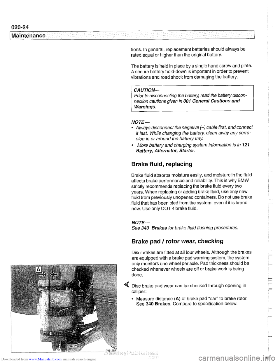
4 Disc brake pad wear can be checked through opening in
caliper:
Measure distance
(A) of brake pad "eai' to bralte rotor.
See
340 Brakes. Compare to specification below.
Page 63 of 1002

Downloaded from www.Manualslib.com manuals search engine
Maintenance
BODY AND INTERIOR MAINTENANCE
Body and hinges, lubricating
Door locksand loclccylinderscan be lubricated with an oil that
contains graphite.
Body and doorhinges, hood latch and doorcheclc rods should
be lubricated with
SAE 30 or SAE 40 engine oil. Lubricate
seat runners with multipurposegrease. Do not apply any oil to
rubber parts.
If door weather-strips are sticking, lubricate
them with silicone spray or talcum powder. The hood release
cable should be lubricated as well.
The use of winter
lock deicer sprays should be lkept to an
absolute minimum, as the alcohol in the deicer will wash the
grease out of the lock assemblies and may cause locks to
corrode internally or to become difficult to operate.
Exterior washing
The longer dirt is left on the paint, the greater the risk of dam-
aging theglossy finish,
eitherby scratching or by thechemical
effect dirt particles may have on the painted surface.
Do not wash the car in direct sunlight. If the engine hood is
warm, allow it to cool. Beads of water not only leave spots
when dried rapidly by the sun or heat from theengine, but also
can act as small magnifying glasses and burn spots into the
finish. Wash the car with a mixture of lukewarm water and a
car wash product. Rinse using plenty of clear water. Wipe the
body dry with a sofl cloth towel or chamois to prevent
water-spotting.
Interior care
Dirt spots can usually be removed with lultewarm soapy water
or a dry foam cleaner. Use spot remover for grease and oil
spots. Do not pour the liquid directly on the carpet or fabric,
but dampen a clean cloth and rub carefully, starting at the
edge of the spot and working inward. Do not use gasoline,
naphtha, or other flammable substances.
Leather upholstery and trim
Leather upholstery and trim should be periodically cleaned
using a slightly damp cotton or wool cloth. The idea is to get
rid of the dirt in the creases and pores that can cause brittle-
ness and premature aging. On heavily soiled areas, use a
mild detergent (such as
wooliteQ) or other specially formulat-
ed leather cleaners. Dry the trim and upholstery completely
Page 71 of 1002

Downloaded from www.Manualslib.com manuals search engine
Two common causes of driveability problems are incorrect
system voltage and bad grounds.
System voltage
Digital motor electronics (DME) requires that the system (bat-
tery) voltage be maintained within a narrow range of DC volt-
age.
DC voltage levels beyond or below the operating range,
or any
AIC voltage in the electrical system can cause havoc.
When troubleshooting an illuminated MIL, make sure the bat-
tery is fully charged and capable of delivering all its power to
the electrical system. An undercharged battery can amplify
AIC alternator output ripple.
To
make a quick check of the battery charge, measure the
voltage across the battery terminals with all cables attached
and the ignition off.
Afully charged battery will measure 12.6
volts or slightly more, compared to 12.1 5 volts for a battery
with a 25% charge.
The DME system operates at low voltage and current levels,
making it sensitive to small increases in resistance. The elec-
trical system is routinely subjected to corrosion, vibration and
wear, so faults or corrosion in the wiring harness and connec-
tors are not uncommon. Check the battery terminals
forcorro-
sion or loose cable connections. See 121 Battery, Starter,
Alternator for additional information.
If a battery cable connection has no
v~sible faults but is still
suspect, measure the voltage drop across the connection. A
large drop indicates excessive resistance, meaning that the
connection is corroded, dirty, or damaged. Clean or repairthe
connection and retest.
NOTE-
For instructions on conducting a voltage drop test and other
general electrical troubleshooting information, see
600 Elec-
trical System-General.
Visually inspect all wiring, connectors, switches and fuses in
the system. Loose or damaged connectors can cause inter-
mittent problems, especially the small terminals in the ECM
connectors. Disconnect the wiring harness connectors to
check for corrosion, and use electrical cleaning spray to re-
move contaminants.
Main grounds
Good grounds are critical to proper DME operation. If a
ground connection has no visible faults but is still suspect.
measure the voltage drop across the connection. A large volt-
age drop means high resistance. Clean or repair the connec-
tion and retest.
LBuntr.yP~sbhnllcn.can#-AII A,~iltl Rcsrwsd
Page 74 of 1002

Downloaded from www.Manualslib.com manuals search engine
I Engine Removal and Installation
Engine removal and installation are covered in this repail
group.
See 100 Engine-General for engine identification details
and engine codes.
Transmission removal is required for all models before the
engine can be removed. This is best accomplished with the
car raised on an automotive lift. For additional procedures re-
quired during engine removal, refer to the following repair
groups:
020 Maintenance
0 121 Battery, Alternator, Starter
170 Radiator and Cooling System
180 Exhaust System
4 230 Manual Transmission
0 240 Automatic Transmission
410 Fenders, Engine Hood
Special tools
Some special tools are required for engine removal and in-
stallation. Be sure to have the necessary equipment on hand
before starting the job.
Engine lifting tool
(Tool No. BMW
11 0 000)
4 Cooling fan counterhold tool
(Tool No. BMW
11 5 030)
< Cool~ng fan wrench
(Tool No. BMW
11 5 040)
Page 77 of 1002

Downloaded from www.Manualslib.com manuals search engine
Engine Removal and lnstallationl
< Remove positive battery cable and intake manifold cover:
Remove protective cover from positive (+)jump start post
(4.
Loosen and remove battery lead mounting nut.
Remove lead and push down through intake manifold
Remove trim covers
(arrows) from fuel injector cover.
Remove cover hold down bolts and lift off cover.
Working above engine, disconnect the following:
Vent line from cylinder head cover (A).
M52 engine: Oxygen sensor connectors (8).
Electrical harness connector from intalte camshaft VANOS
solenoid valve
(C).
M52 engine: Disconnect electrical harness connectors at
throttle valve position switch
(D), ASC valve position switch
(E), fuel injector harness (F) and vent valve (G).
CAUTION-
Be sure to mark oxygen sensor harness connectors so that
they can be reassembled correctly Do not interchange con-
nectors.
4 M52 TU, M54 engine: Disconnect fuel injector electrical con-
nectors from injectors.
Use small screwdriverto pry one corner of wire lock clip on
fuel injector
1 connector.
Repeat for all injectors.
Lifl off connector loom and lay aside.
Page 82 of 1002

Downloaded from www.Manualslib.com manuals search engine
.-
-6val and Installation -
< Remove intake manifold mounting hardware (arrows).
NOTE-
M52 TU engine shown. M52 and M54 engines are similar.
Liit up manifold just enough to remove positive cables from
starter motor terminal
50 (arrow).
- Remove intake manifold from cylinder head while carefully
checking for electrical connections, tie wraps, and hoses.
CAUTION-
Stuff clean rags into open intake ports to prevent any parts
from falling into the engine intake.
4 Remove fastener (A) and harness connector (B) from
alternator.