Page 58 of 1002

Downloaded from www.Manualslib.com manuals search engine
020-26
Maintenance
NOTE-
The parking brake may lose some of its effectiveness if it is
not used frequently This is due to corrosion build-up on the
parking brake drum. To remove corrosion, apply the parking
brake just until it begins to grip, then pull the lever up one
more stop (click). Drive the car approximately 400 meters
(1,300
ft.) and release the brake. To recheck the adjustment
of the parking brake see
340 Brakes.
Clutch fluid, checking
In cars equipped with manual transmission and clutch, the hy-
draulic clutch and the brake system share the same reservoir
and the same bralte fluid. Clutch fluid level and brake fluid lev-
el are checked at the same time.
NOTE-
* See 340 Brakes for more information.
See
210 Clutch for information on the clutch and the
hydraulic clutch operating system.
Differential oil level, checking
The E39 differential is filled with lifetime oil that ordinarily
does not need to be changed.
BMW recommends using only
a specially formulated synthetic gear oil
(SAF-XO) that is
available through an authorized
BM\N dealer parts depart-
ment. For additional information on this lubricant and any
other lubricants that may be compatible, contact an
authorized
BMW dealer service department.
< Check rear differential oil level at filler plug (arrow).
- Check lubricant level with car on a level surface:
Level is correct when fluid just reaches edge of filler hole.
If necessary, top up fluid.
Replace filler plug sealing ring.
Install and tighten oil filler plug when oil level is correct.
NOTE-
Use either a 14 mm or 17 mm Allen socket to remove the
drain plug.
If the car is raised in the air, it should be level when
checking or filling final drive fluid level.
Tightening torque
Filler plug to final drive housing 70 Nrn (52 it-lb)
Page 93 of 1002

Downloaded from www.Manualslib.com manuals search engine
--
-- Engine Removal and installation' -
Remove polyribbed A/C compressor belt:
Mark direction of belt travel if belts are to be reused.
Loosen bolts
(A).
Turn adjusting lug (B) clocltwise to release belt tension.
Working beneath car, remove power steering pump and air
conditioner compressor. Suspend from body using stiff wire.
Remove exhaust manifolds. See
180 Exhaust System.
< lnstall engine lifting device (BMW 11 0 000 or equivalent) to
front and rear engine supports and raise engine until it's
weight is supported. Detach engine mounts.
a Watch carefully for hoses and electrical wires that might
snag.
- installation is reverse of removal:
Replace all gaskets, O-rings and seals.
V-8 engine mounts have two sets of mounting holes. E39
cars use front most mounting holes.
* On cars with automatic transmission, use new O-rings at
ATF cooler lines.
Use new alignment sleeves when installing transmission.
Be sure engine drive belts properly engage pulley grooves.
When installing belt, preload tensioner to stop (toward
belt), then tighten tensioner clamping nut.
lnstall front exhaust pipes using new gasltets and copper
paste and new mounting hardware. See
180 Exhaust
System.
Change engine oil and filter. Check all other fluid levels as
described in
020 Maintenance.
Refill and bleed cooling system as described in
170 Radi-
ator and Cooling System.
CAUTION-
Do not interchange knoclc sensor harness connectors. Seri-
ous engine damage may result
Page 106 of 1002
Downloaded from www.Manualslib.com manuals search engine
-
Cylinder Head Removal and Installation c
q Remove secondary air inject~on check valve (arrow).
4 Remove cylinder head top cover:
Remove plastic trim caps (arrows).
Remove engine oil filler cap.
Remove cover hold down fasteners and lift off cover.
4 Remove ignition coils:
Disconnect ignition coil harness connectors.
. Remove coil mounting fasteners.
Remove coils.
Remove ground straps.
NOTE-
Make note of ground wire at mounting studs arrangement
during removal.
- Remove sparlc plugs.
- Remove cylinder head cover mounting fasteners and remove
cylinder head cover.
NOTE-
The cylinder head cover mounting bolt insulators and gas-
lets should be reinstalled in their original locations. Make
note of their arrangement during removal.
Page 107 of 1002
Downloaded from www.Manualslib.com manuals search engine
- - , -. I Cylinder Head Removal and lnstallatio~
4 Remove oil baffle cover from above intake camshaft.
4 Unscrew and remove three cylinder head cover studs (ar-
rows)
at rear of cylinder head.
Set engine to approximate top dead center
(TDC) by turning
crankshaft bolt in direction of rotation (clocltwise when
viewed from front of engine) until camshaft lobes for cylinder
1 face each other (dotted lines) and arrows on camshaft
sprocltets face up.
- Set engine to TDC by aligning "OIP mark of vibration damp-
er with boss cast on lower timing chain cover.
< Lock cranltshaft at TDC:
Remove sealing plug from bore on lower left side of engine
block below starter. Secure crankshaft in
TDC position with
BMW special tool 11 2 300.
Page 124 of 1002

Downloaded from www.Manualslib.com manuals search engine
Cylinder Head Removal and installation - - .- - - - -
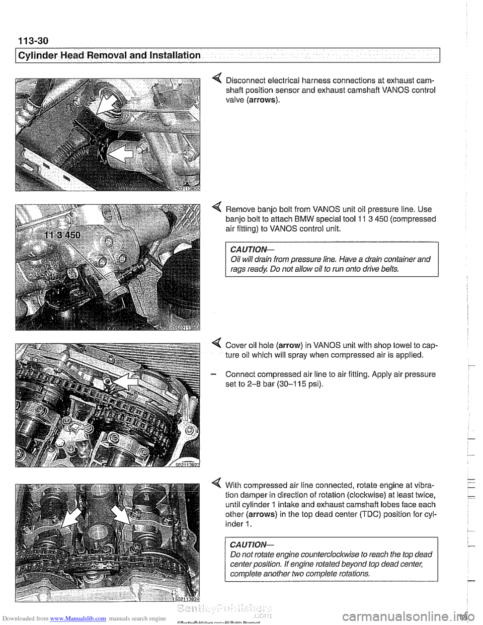
4 Disconnect electrical harness connections at exhaust cam-
shaft position sensor and exhaust camshaft VANOS control
valve (arrows).
4 Remove banjo bolt from VANOS unit oil pressure line. Use
banjo bolt to attach
BMW special tool 11 3 450 (compressed
air fitting) to VANOS control unit.
CAUTIOI\C
Oil will drain from pressure line. Have a drain container and
rags ready Do not allow oil to run onto drive belts.
4 Cover oil hole (arrow) in VANOS unit with shop towel to cap-
ture oil which will spray when compressed air is applied.
- Connect compressed air line to air fitting. Apply air pressure
set to
2-8 bar (30-1 15 psi).
4 With compressed air line connected, rotate engine at vibra-
tion damper in direction of rotation (clockwise) at least twice,
until cylinder 1 intake and exhaust camshaft lobes face each
other (arrows) in the top dead center (TDC) position for cyl-
inder
1.
CAUTION--
Do not rotate engine counterclocltwise to reach the top dead
center position. If engine rotated beyond top dead center;
complete another two complete rotations.
Page 134 of 1002

Downloaded from www.Manualslib.com manuals search engine
11 3-40
I Cylinder Head Removal and Installation
Lubricate camshafts, camshaft carriers, bearing caps, hy-
draulic lifters, friction washers, splined shafts and spline hubs
with assembly lubricant before installation.
4 Check that two cylinder head aligning sleeves (arrows) are
correctly positioned in block and are not damaged.
- Apply elastic sealing compound Three Bond 1209 8 to cor-
ner joints on cylinder block to timing chain cover.
- Place new cylinder head gasket on cylinder block.
NOTE-
The word "OBEN" or "TOP printed on the gasket, should
face up. The cylinder headgaslet will fit correctly in only one
orientation.
- Set cylinder head in position, guiding primary chain through
cylinder head opening.
CAUJION-
Make sure the crankshaft, which had been rotated approxi-
mately 30" opposite the direction of engine rotation from
TDC, is still in thatposition before lowering the cylinder head
into position. All pistons must be out of TDC position to pre-
vent
valve/piston interference when the camshafts are in-
stalled.
- Lightly lubricate new cylinder head bolts and washers with
oil. Install bolts and washers finger tight. Install cylinder head
to lower timing chain cover bolts finger tight.
NOJE-
Cylinder head bolts should not be reused. They are
stretch-type bolts and must be replaced whenever loos-
ened.
* Aluminum cylinder blocls use different length cylinder
head bolts and torque values than cast iron blocks.
Check that all washers for
Nle head bolts are in place be-
fore installing the bolts. Some of the washers may be
staked to the cylinder head.
I 12 10 4 2 6 8 141 Tighten cylinder head bolts in correct sequence (1-14)
CA U TIOW-
The bolts should be tightened in three stages as listed below
The final stages require the use of a BMW special tool
11 2
110 or a suitable protractor to tighten the bolts to a specified
torque angle.
Page 145 of 1002
Downloaded from www.Manualslib.com manuals search engine
113-51
Cylinder Head Removal and Installation
< Pull out exhaust camshaft splined shaft to stop.
- Press down on secondary chain tensioner and remove ten-
sioner lock-down tool.
Preload primary chain:
Tighten adjusting screw on
BMW special tool 11 4 220 to
specified torque.
Tightening torque
Primary chain tensioner preload
0.7 Nrn (6 in-lb)
< Preload exhaust camshaft sprrng plate by pressing on im-
pulse wheel while tightening mounting nuts (arrows) finger
tight.
Install BMW special tool 11 6 150 (VANOS setup bracket) to
front of cylinder head timing case. Install nuts (arrows) finger
tight, then tighten down uniformly until special tool is in full
contact with cylinder head.
CAUTION-
Make sure all gasket material is removed from face of cylin-
der head. Clean sealing
face and keep free of oil. If any for-
eign material is present on the sealing
sudace, the camshait
timina will be incorrect.
Page 147 of 1002

Downloaded from www.Manualslib.com manuals search engine
Cylinder Head Removal and Installation /
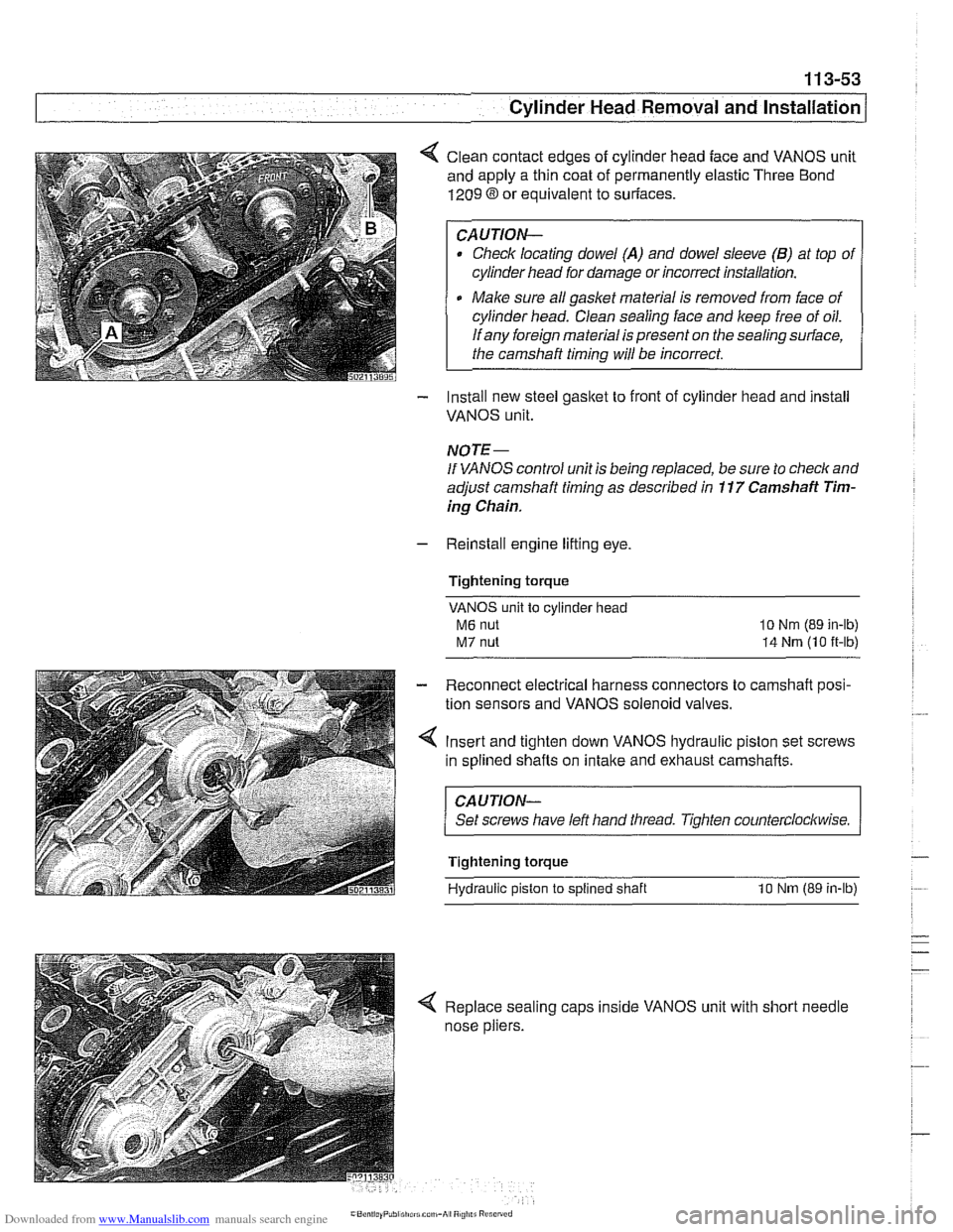
< Clean contact edges of cylinder head face and VANOS unit
and apply a thin coat of permanently elastic Three Bond
1209 8 or equivalent to suriaces.
CAUTION-
Check locating dowel (A) and dowel sleeve (B) at top of
cylinder head for damage or incorrect installation.
Make sure all gasket material is removed from face of
cylinder head. Clean sealing face and keep free of oil.
If any foreign material is present on the sealing surface,
the camshaft timing will be incorrect.
- Install new steel gasket to front of cylinder head and install
VANOS unit.
NOTE -
If VANOS control unit is being replaced, be sure to check and
adjust camshaft timing as described in
11 7 Camshaft Tim-
ing Chain.
- Reinstall engine lifting eye.
Tightening torque
VANOS unit to cylinder head
M6 nut
M7 nut
lo Nm (89 in-lb)
14 Nrn (10 it-lb)
- Reconnect electrical harness connectors to camshaft posi-
tion sensors and VANOS solenoid valves.
4 Insert and tighten down VANOS hydraulic piston set screws
in splined shafts on
intake and exhaust camshafts.
CAUJION-
Set screws have left hand tliread. Tighten counterclockwise.
Tightening torque
Hydraulic piston
to splined shaft 10 Nm (89 in-lb)
< Replace sealing caps inside VANOS unit with short needle
nose pliers.