1998 BMW 540i Power steering
[x] Cancel search: Power steeringPage 331 of 1002

Downloaded from www.Manualslib.com manuals search engine
Lubrication system/
4 Install engine lifting tool at front of engine and raise engine
approximately
5 mm (114 in).
< Remove pinch bolt (arrow) at steering column universal joint
near steering rack. See
320 Steering and Alignment.
- Remove power steering pump, leaving hydraulic lines con-
nected to pump. Suspend pump using strong wire. See
320
Steering and Wheel Alignment.
NOTE-
For better access to power steering assembly, unbolt fluid
reservoir and suspend with wire.
Loosen upper nuts (arrow) in right and lefl engine mounts,
< Remove right and left lower engine mount nuts (arrow)
- On cars with automatic transmission, remove ATF cooler line
brackets from engine oil pan.
- Disconnect electrical harness connector at oil level sensor on
oil pan.
Page 337 of 1002

Downloaded from www.Manualslib.com manuals search engine
1 19-1 7
Lubrication System
Disconnect electrical harness connect01
sensor.
. (arrow)
4 Remove lower oil pan bolts (arrows) and pan, oil
level
CAUTION-
If the lowerpan does not separate easily from upperpan, a
few taps with a rubber mallet should break it free. Do not pry
the oil pan loose.
Remove
NC drive belt tensioner.
Remove adjustment bolt
(B).
Remove retaining bolt (A) and remove tensioner from oil
pan.
- Remove power steering pump from engine block, leaving hy-
draulic lines connected. Suspend from chassis using stiff
wire. See
320 Steering and Wheel Alignment.
Page 381 of 1002

Downloaded from www.Manualslib.com manuals search engine
Battery, Starter, ~lternatorl
Alternator, removing and installing
(6-cylinder engine)
A replacement alternator should have the same rating as the
original. Alternator manufacturer and ampere rating are nor-
mally marked on the alternator housing.
- Disconnect negative (-) battery cable.
CAUTION-
Prior to disconnecting the batteg read the battery discon-
nection cautions given
in 001 General Warnings and Cau-
I tions.
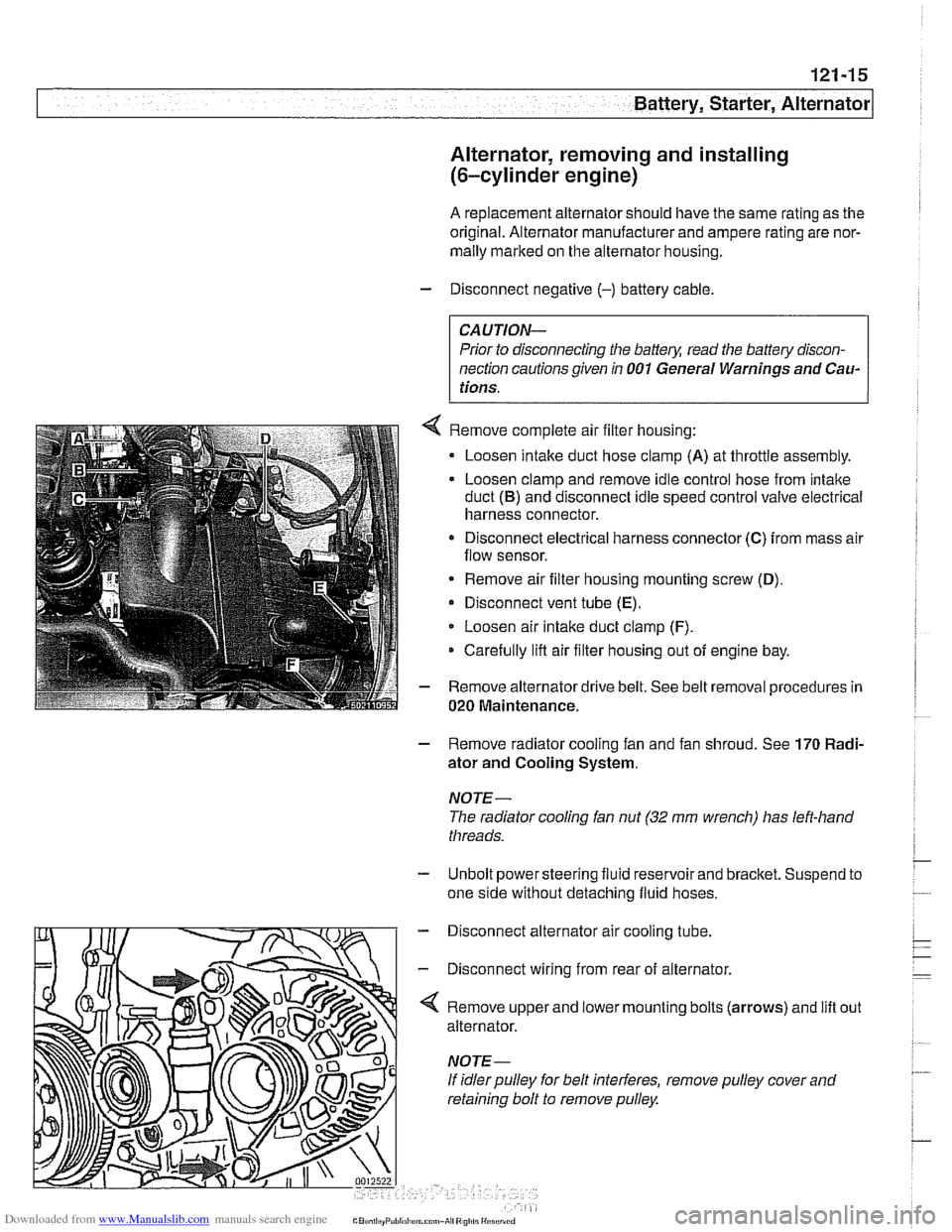
Remove complete air filter housing:
Loosen intake duct hose clamp
(A) at throttle assembly.
Loosen clamp and remove idle control hose from intake
duct
(B) and disconnect idle speed control valve electrical
harness connector.
Disconnect electrical harness connector
(C) from mass air
flow sensor.
* Remove air filter housing mounting screw (D),
Disconnect vent tube (E).
Loosen air intake duct clamp (F).
Carefully lifl air filter housing out of engine bay.
Remove alternator drive belt. See belt removal procedures in
020 Maintenance.
- Remove radiator cooling fan and fan shroud. See 170 Radi-
ator and Cooling System.
NOTE-
The radiator cooling fan nut (32 mm wrench) has left-hand
threads.
- Unbolt power steering fluid reservoir and bracket. Suspend to
one side without detaching fluid hoses.
- Disconnect alternator air cooling tube.
- Disconnect wiring from rear of alternator.
'4 Remove upper and lower mounting bolts (arrows) and lift
alternator.
If idler pulley for belt interferes, remove pulley cover and
retaining bolt to remove pulley. out
Page 469 of 1002

Downloaded from www.Manualslib.com manuals search engine
Fuel Injection I
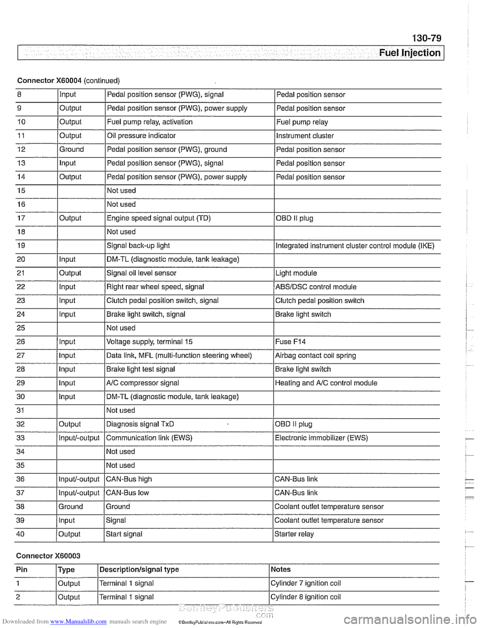
Connector X60004 (continued)
8 10
11
12
13
14
15
16
9
Output 0
Input
17
18
19
20
21
22
23
24
25
26
27
28
29
30
31
32
33
34
35
36
39
llnput lsignal l~oolant outlet temperature sensor
Output
Output
Ground
Input
Output
I I - I
40 /output Istart signal Istarter relay
Pedal position sensor (PWG), signal
Output Input
Output
input
Input
Input
Input
Input
Input
input
Input
Output
Input/-output
Input/-output
37
Connector X60003
Pedal position sensor
Fuel pump relay, activation
Oil pressure indicator Pedal position sensor (PWG), ground
Pedal position sensor (PWG), signal
Pedal position sensor (PWG), power supply
Not used
Not used Fuel
pump relay
Instrument cluster
Pedal position sensor
Pedal position sensor
Pedal position sensor
Engine speed signal output (TD)
Not used
Signal
back-up light
DM-TL (diagnostic module,
tank leakage)
Signal oil level sensor
Right rear wheel speed, signal
Clutch pedal position switch, signal
Brake light switch, signal
Not used
Voltage supply, terminal
15
Data link, MFL (multi-function steering wheel)
Brake light test signal
AJC compressor signal
DM-TL (diagnostic module, tank
leakage)
Not used
Diagnosis signal
TxD
Communication link (EWS)
Not used
Not used
CAN-BUS hiqh
38 1 Ground l~round I Coolant outlet temperature sensor
OED II plug
Integrated instrument cluster control module (IKE)
Light module
ABSIDSC control module
Clutch pedal position switch
Brake light switch
Fuse
F14
Airbag contact coil spring
Brake light switch
Heating and
A/C control module
OBD
II plug
Electronic immobilizer (EWS)
CAN-Bus link
CAN-Bus link
Input/-output CAN-Bus low
Page 625 of 1002

Downloaded from www.Manualslib.com manuals search engine
300-5
Suspension, Steering and Brakes - ~enerall
The E39 rear suspension subframe is used as a rigid mount-
ing platform
forthe differential (also called final drive) and rear
suspension components. The differential is mounted to the
subframe and the subframe is bolted to the body through rub-
ber bushings which help isolate drivetrain noise and vibration.
The
€39 rear suspension is known as a modified multi-link
system. Three control arms on each side locate the rear
wheels.
The lowercontrol arm, called the swing arm, is attached to the
wheel bearing carrier through a pivoting integral link.
An eccentric mounting bolt at the rear inner mounting of the
swing arm is used for rear camber adjustment.
The inner end of the upper front control arm, called the trac-
tion strut, is also mounted with an eccentric fastener, used to
adjust rear toe.
Drive axles with constant-velocity (CV) joints at both ends
transfer power
from the differential to the road wheels.
Sedan models
The rear suspension in sedan models uses coil springs over
strut shock absorbers. The bottom of each strut bolts to the
wheel
carrier.The top strut mount attaches just below the rear
parcel shelf of the car.
Sedan models fitted with EDC (Electronic Dampening Con-
trol) use air struts.
Page 630 of 1002

Downloaded from www.Manualslib.com manuals search engine
300-1 0
/Suspension, Steering and Brakes - General
The steering system features variable power assist provided
by an engine-driven hydraulic pump.
Rack and pinion steering
6-cylinder models
(525i, 5281, 5300
Two types of steering systems are used in E39 models. 6-
cylinder (525i, 5281, 530i) models are equipped with a steer-
ing rack system. V-8
(540i) models are equipped with a re-
circulating ball and nut steering gearbox.
Rack-and-pinion steering
Steering components in 6-cylinder models consist of a rack-
and-pinion type steering gear and connecting linltage to the
road wheels.
The steering linkage connects the rack-and-pinion unit
through tie rods to the steering knucltles. The tie rod ends al-
low the wheels to pivot and react to suspension travel.
Recirculating ball and nut steering
V-8 models
(540i)
I
Recirculating ball and nut steering
Recirculating ball and nut steering in V-8 models consists of a
steering box with integrated hydraulic control valve and con-
necting linkage to the road wheels.
Thesteering linkageconnects the steering gearbox through a
pitman arm to the wheels. An idler arm maintains correct toe
angle. The tie rod allow the wheels to pivot and react to sus-
pension travel.
E39 cars are equipped with power disc brakes with integral
antilock brakes (ABS). The parking bralte is a dual-drum sys-
tem integrated with the rear brake rotors.
Power assist is provided by a vacuum booster when the en-
gine is running. The brake pedal
pushrod is connected direct-
ly to the master cylinder, so failure of the vacuum booster
does not normally result in total
bralte failure.
Each disc bralte uses a caliper with a single hydraulic cylin-
der. Brake pads in the left front and right rear contain wear
sensors. When brake pads need replacement, the sensors il-
luminate a light on the dashboard.
Page 632 of 1002

Downloaded from www.Manualslib.com manuals search engine
300-1 2
I Sus~ension, Steerincl and Brakes - General
E39 electronic brake and stability control
systems application table
(528i, 54bi) Traction (ASC) I Hydraulic unit in right rear of engine compartment 1
Identifiers
Year (model)
I No precharge pump 1
Manuf. up to 911998 l~utomatic Stability Control plus I Electronic control module next to glove compartment
System
Precharge pump in
lefl front of engine compartment, below
steering fluid reservoir
Separate rotational rate (yaw) and lateral acceleration sensors
I I
Combined rotational rate (yaw) and lateral acceleration sensors
Electronic control
module next to glove compartment
Hydraulic unit in right rear of engine compartment
Manuf. up to 911999
(540i optional)
I I
ABS system
Dynamic Stability Control (Bosch
DSC
Ill v. 5.3)
The electronically controlled
ABS maintains vehicle stability
and control during emergency braking by preventing wheel
lock-up.
ABS provides optimum deceleration and stability dur-
ing adverse conditions. It automatically adjusts brake system
hydraulic pressure at each wheel to prevent wheel lock-up.
Control
moduleihydraulic unit
in right rear of engine compartment
No precharge pump
Manuf. from
911999
(all models)
Automatic Stability Control (ASC)
Dynamic Stability Control (Boscli
DSC Ill v. 5.7)
NOJE-
ASC (Automatic Stability Control) may also be referred to as
ASCiT (Automatic Stability ControkTraction).
ASC works in conjunction with ABS and the engine manage-
ment system to enhance vehicle control. The main function of
the
ASC system is to maintain the contact between the tires
and the road surface under all driving conditions. This is
achieved through exact application and management of brak-
ing and drivetrain forces.
The
ASC system improves traction by electronically applying
the rear brakes when the rear drive wheels are spinning at a
faster rate than the front wheels. The combined
ABSIASC
control module, operating through the ABS hydraulic control
unit, modulates braking force at the rear wheels.
In addition,
ASC overrides the throttle opening to reduce en-
gine torque and maintain vehicle traction. Because the throt-
tle is controlled electronically, the driver cannot increase
engine power output during
ASC intervention regardless of
how far the accelerator pedal is pushed.
Page 659 of 1002

Downloaded from www.Manualslib.com manuals search engine
1 320 Steering and Wheel Alignment
General ........................... .32 0.2
Special tools
........................ .32 0.2
Steering system
..................... .32 0.4
Steering system variations
............. .32 0.5
Steering system warnings and cautions
... .32 0.6
Steering Wheel .................... .32 0.7
Steering wheel. removal and installation
.. .32 0.7
Steering Column ................. .32 0.1 0
Steering column components .......... .32 0.10
Steering column trim, removing
and replacing
...................... .32 0.10
lgnition switch ring antenna (EWS).
removing and installing
............... .32 0.1 1
lgnition lock cylinder.
removing and installing
............... .32 0-1 1
Steering column lock. removing
and installing
....................... .32 0.12
lgnition
interloclc cable. removing and installing
(models with automatic transmission)
... .32 0.13
Interlock cable. adjusting
(models with automatic transmission)
... .32 0.14
Steering column. removing and installing
. .32 0.14
Steering column adjustment motors.
removing and installing
............... .32 0.16
Power Steering Pump ............. .32 0.17
Power steering pump. removing
and installing
....................... .32 0.1 7
Power steering system.
bleeding and filling
.................. .32 0.18
Rack and Pinion Steering
(6-cylinder models)
............... 320-19
Rack and pinion steering components
(6-cylinder models)
.................. 320-1 9
Steering rack. removing and installing
.... 320-19
Steering
rack boot. replacing ........... 320-22
Tie rod (outer). replacing
.............. 320-22
Tie rod (inner). replacing
.............. 320-23
Steering Gearbox (V-8 models) .... 320-24
Steering gearbox system components
. .
(V-8 models) ....................... 320-24
Steering gearbox, removing and installing 320-25
Pitman arm. removing and installing ..... 320-28
Pitman arm. adjusting ................ 320-29
Steering idler arm. removing
and installing
....................... 320-30
Idler arm bushing. replacing ........... 320-31
Center tie rod. replacing
.............. 320-32
Wheel Alignment .................. 320-33
Camber
........................... 320-33
Caster
............................ 320-33
Front toe and toe difference angle
....... 320-34
Reartoe ........................... 320-34
Preparing for alignment
............... 320-35
Alignment specifications tables
......... 320-35