1998 BMW 528i electrical wiring
[x] Cancel search: electrical wiringPage 742 of 1002

Downloaded from www.Manualslib.com manuals search engine
Rear Suspension
4 Remove air line fittings (A) from bottom of air distribution con-
nectors.
Cut off wire ties.
WARNING-
Vehicle will lower when the air pipes are opened.
4 Rotate air line distribution connector (A) 45" in direction of
arrow to remove.
Rotate electrical connector
(B) 45" in direction of arrow to
remove.
Compress wiring connector locking clips
(arrows) and dis-
connect wiring harness.
< Remove air supply unit mounting fasteners (arrows) and re-
move unit.
- Installation is reverse of removal.
When installing air lines always match line colors.
a After assembly, reset ride height using BMW diagnostic
scan tool DIS.
Page 813 of 1002

Downloaded from www.Manualslib.com manuals search engine
Fenders, Engine ~ood/
Hood, removing and installing
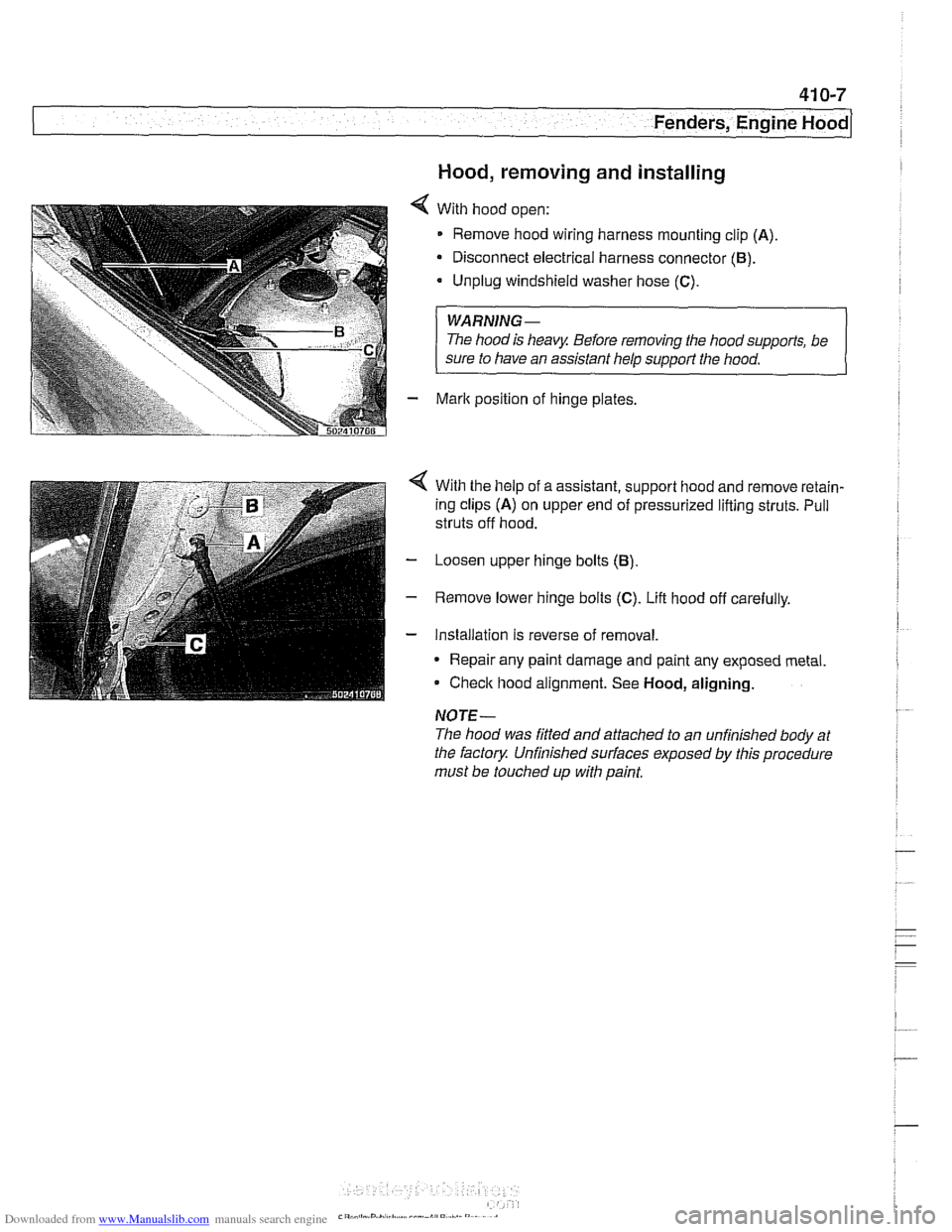
With hood open:
Remove hood wiring harness mounting clip
(A)
Disconnect electrical harness connector (B).
Unplug windshield washer hose (C).
WARNING-
The hood is heavy Before removing the hoodsupports, be
sure to have an assistant help
support the hood.
Mark position of hinge plates.
With the help of a assistant, support hood and remove retain-
ing clips
(A) on upper end of pressurized lifting struts. Pull
struts off hood.
Loosen upper hinge bolts
(B)
Remove lower hinge bolts (C). Lift hood off carefully.
Installation is reverse of removal.
* Repair any paint damage and paint any exposed metal
Check hood alignment. See
Hood, aligning.
NOTE-
The hood was fitted and attached to an unfinished body at
the factory Unfinished
sun'aces exposed by this procedure
must be touched up with paint,
Page 831 of 1002

Downloaded from www.Manualslib.com manuals search engine
Trunk Lid, Tailgate
4 Pry out trunk light and disconnect electrical harness plug
connector.
- Gently pry trunk liner away from lid and remove.
4 Disconnect Wiring connectors A, B and C. Remove wiring
harness by pulling through opening in lid frame
D.
While supporting trunk lid, loosen left and right top hinge fas-
teners (arrow
A) and remove lower fasteners (arrow B).
NOTE-
Before loosening hinge bolts, mark hinge and hinge bolt lo-
cations for
reins~alla~on
Lift trunk lid straight up to remove.
Installation is reverse of removal. If necessary, align trunk lid
to body as described in
Trunk lid, adjusting.
Page 876 of 1002

Downloaded from www.Manualslib.com manuals search engine
512-12
I Door Windows
- Disconnect window from window guide rail as described in
Door window, removing
and installing. Do not remove
window from door.
* Push window up and use wedge to hold in position.
- If necessary, remove speaker unit from door.
- Removing window regulator from door:
Disconnect window motor electrical harness connector.
4 Remove lower window regulator fasteners (arrows).
Remove window regulator fasteners (arrows)
Loosen fasteners (arrows) and slide regulator up to remove
from mounts.
- Remove window regulatorthrough opening in bottom of door,
checking for any wiring that might become snagged during
removal.
- Installation is reverse of removal.
Be sure to route wiring harnesses to keep them away from
moving window mechanism. Use new wire ties as neces-
sary.
-
Tightening torques -
Window motor to regulator 5 Nm (44 in-lb)
502512211
Window regulator to door 8 Nm (71 in-lb)
Adjust window
as described earlier.
- -
W~ndow to guide 8 Nm (71 in-lb)
--
Page 896 of 1002

Downloaded from www.Manualslib.com manuals search engine
51 5-2
/Central Locking and Anti-Theft
This section covers repair information for door, trunk and car-
go compartment locks, central locking, electronic
immob~liza-
tion (EWS) and anti-theft alarm (DWA).
€39 cars are equipped with sophisticated self-diagnostic elec-
trical systems. When experiencing malfunctions relating to
central locking. EWS or anti-theft systems, start the diagnosis
process using the
BMW service tester DIS, GT 1, MoDiC or
equivalent scan tool. An advanced diagnostic scan tool can
usually pinpoint electrical faults quickly and safely.
Additional electrical information can be found in:
610 Electrical Component Locations
ELE Electrical Wiring Diagrams
Central locking in E39 vehicles controls the door
locks, trunk
or tailgate lock and fuel filler flap lock. The control module for
the Central Body Electronics system (ZKE
Ill), lknown as the
General Module (GM
Ill), controls central locking.
ZKE
Ill manages the following central locking related func-
tions:
Central locking
* Keyless entry
Key memory
Power trunk release
Electric opening of tailgate
DWA alarm system
Diagnosis
General Module
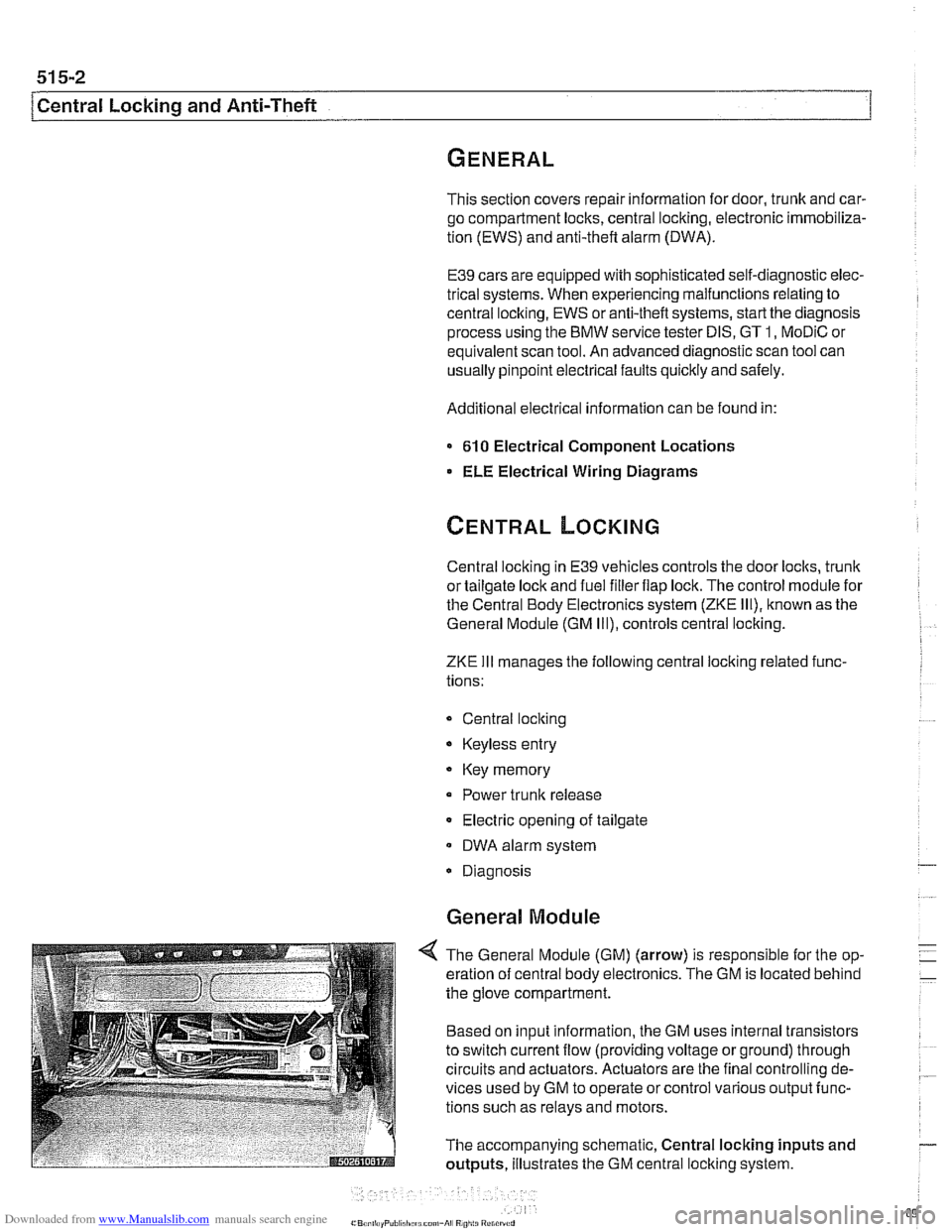
4 The General Module (GM) (arrow) is responsible for the op-
eration of central body electronics. The GM is located behind
the glove compartment.
Based on input information, the GM uses internal transistors
to switch current flow (providing voltage or ground) through
circuits and actuators. Actuators are the final controlling de-
vices used by GM to operate or control various output func-
tions such as relays and motors.
The accompanying schematic, Central locking inputs and
outputs, illustrates the GM central locking system.
Page 958 of 1002

Downloaded from www.Manualslib.com manuals search engine
721 -1 0
/Airbag System (SRS)
4 Pry up cover from top of passenger side airbag on dash-
board.
4 Remove airbag mounting bolts (arrows)
- Lift airbag and disconnect electrical harness connector. Re-
move
airbag.
WARNING-
Store the removed airbag unit with the soft pad facing up. If
stored facing down, accidental deployment could propel it vi-
olentlv into the
ail: causino inium
- Installation is reverse of removal. Make sure wiring harness
is not pinched when installing
airbag unit in dashboard.
Tightening torques
-
Passenger alr bag to 10 NM (88 in-lb)
dashboard (Me)
Door mounted side-impact airbag,
removing and installing
- Disconnect negatlve (-) cable from battery and cover nega-
tive terminal with insulating material.
CAUTION-
Prior to disconnecting the battea read the battery discon-
nection cautions given
in 001 General Warnings and Cau-
tions.
- Remove inside door panel as described in 41 1 Doors
Page 994 of 1002

Downloaded from www.Manualslib.com manuals search engine
4 INDEX
Door window anti-trap
512-4 convenience openinglclosing 512.4
regulator and motor 512-1 1
service
512-5 switches 512-3
see also Switches
Double
VANOS see VANOS
Drive
axle
CV joint 331-15 CV joint boot 331-15
rernovinglinstalling 331-14
Drive belt
see Maintenance
Driveabiiity troubleshooting
100-4
Driveaway protection
see EWS (eiectronic immobilization)
Driveshaft aligning
260-7
center bearing, replacing 260-12 CV joint, replacing 260-14
itex-disc, replacing 260-1 1
iront centering guide, replacing 260-13
rernovinglinstailing 260-6
lroubleshooting 260-3
U-joint 260-3
DSC
see Braires
DTC (diagnostic trouble code)
OBD-8
DWA
see Anti-theft alarm
ECM (engine control module)
see 130 under appropriate
iuei
injection system
ECT (engine coolant temperature)
sensor see 130 under appropriate
iuei
injection system
EDK adaptation
130-69
MS 43.0 130-35
EHC see Electronic iieigiit control (EHC)
Electric cooling fan
see Cooling system, cooling
fan
see also Cooiing system, eiectric fan
Electrical switches
see Switches
Electrical system abbreviations
600-14 bus System 600-4
component location table 610-3
components
photos
610-36
Sport Wagon 610-81 engine 121-2
troubleshooting 600-15
voltage and polarily 600-5 wire color codes 600-12
wiring diagrams 600-12
Electrical wiring diagrams
ELE-1
Eiectricaliy heated thermostat
(characteristic map)
170-4
Eiectronic height control (EHC)
300-8, 330-44
Eiectronic immobilization
see EWS (electronic immobilization)
Eiectronics box
(E-box)
610-37
Emergencies
010-18
Emergency brake see
BraBes, parking brake Engine
see also Cylinder head and valvetrain
applications
100-2
compression, testing 113-5
cooling see Cooiing system
crankshaft front oil seai
see Crankshaft oil seals
cyiinder leak-down test 113-8
diagnostic testing 113-1
drive belts
see Maintenance
driveability troubleshooting
100-4
engine management systems 100-2
see also Ignition
see also Fuel injection
fuel supply
130-6
ground connections 100-5
see also 61 0 identilying ieatures 100-3
lubrication svstem
see
~ubricetion system
mount
on-board diagnostics
OBD-I
oxygensensor
see Fuel injection
see also Exhaust system
Dreventive maintenance
see Maintenance
removal/installation
Engine control module (ECM)
see 130 under appropriate iuel
injection system
Engine cooiant temperature (ECT)
sensor see 130 under appropriate iuel
injection
system
Engine cooling fan
see Cooiing system, electric fan
Engine hood
41
0-6 raising to service position 410-6
Engine troubleshooting
see Engine, driveability troubleshooting
EVa~oratiVe control svstem
160-3 see also 130 under aDDroDriate iuel
injection system
Evaporator see
NC
Evaporator temperature sensor see
NC
Page 1002 of 1002

Downloaded from www.Manualslib.com manuals search engine
112 INDEX
Warnings 001-1
Warnings, cautions and notes
01
0-3
Washer fluid pump
see Wipers and washers
Washers see Wipers and washers
Washing see Maintenance
Water pump
see Cooling system, coolant
pump
Waxing
see Mainienance
Wheel, steering
see Steering
Wheel alignment
320-33 ride [height 300-14
see also Maintenance
Wheel bearing
see Front suspension
see also Rear suspension
Wheels
300-1 1
Window motor see Door window
Window regulator
see Door window
Window switch
512-3
see Switches
Windows, door
see Door window
Windshield wipers and washers
see Wipers and washers
see also Maintenance
Wiper motor
see Wipers and washers Wipers and
washers
rain sensor 61
1-6 rear window (Sport Wagon) wiper motor, removingiinstaiiing
611-15 wiper shaft, removing.instaiiing
611-15
wiperiwasher system 61
1-8 washer system 611-16
wiper
assembly 611-12
wiper blades and arms 61 1-9
Wiring codes and abbreviations
600-12
Wirinq diaarams ELF-I -
see also Electrical system
Working under car safely
010-6
Xenon headlght
630-6
ZKE (central body electronics)
600-8