Page 49 of 1002
Downloaded from www.Manualslib.com manuals search engine
< 6-cylinder engine with hydraulic belt tensioners.
Use long-handled wrench to turn
A/C belt tensioner (A)
clockwise. Remove AfC belt.
* Similarly, turn main engine drive belt tensioner (B)
clockwise and remove belt.
< Some models have a dust cover over belt tensioner release
lug, which must be pried off prior to removing belt.
4 6-cylinder engine with spring-loaded belt tensioners.
Use long-handled wrench to turn
AfC belt tensioner
release lug
(A) clocltwise (against spring tension).
Remove
AfC belt.
Similarly, turn main engine drive belt tensioner lug
(B)
clocltwise and remove belt.
Page 50 of 1002
Downloaded from www.Manualslib.com manuals search engine
020-1 8
Maintenance
V-8 engine drive belt diagram (NC belt not shown).
NOTE-
Two types of belt tensioners are used on the V-8 engines.
The tensioner shown in this procedure is for cars built up to
8/97. The later style tensioner is similar.
4 V-8 engine tensioner.
Loosen
fasteners(A) to relieve belt tension
- Remove drive belt.
4 When reinstalling belt, check that it is correctly positioned on
belt pulleys.
With bolts
(B and C) finger tight, pretension adjuster by
turning hex counterclocltwise
(arrow) to stop.
Tighten mounting bolts.
NOTE-
On 8/97 and later tensioner, turn hex on tensioner plate to
align lowerplate mounting bolt.
Page 51 of 1002

Downloaded from www.Manualslib.com manuals search engine
Maintenance
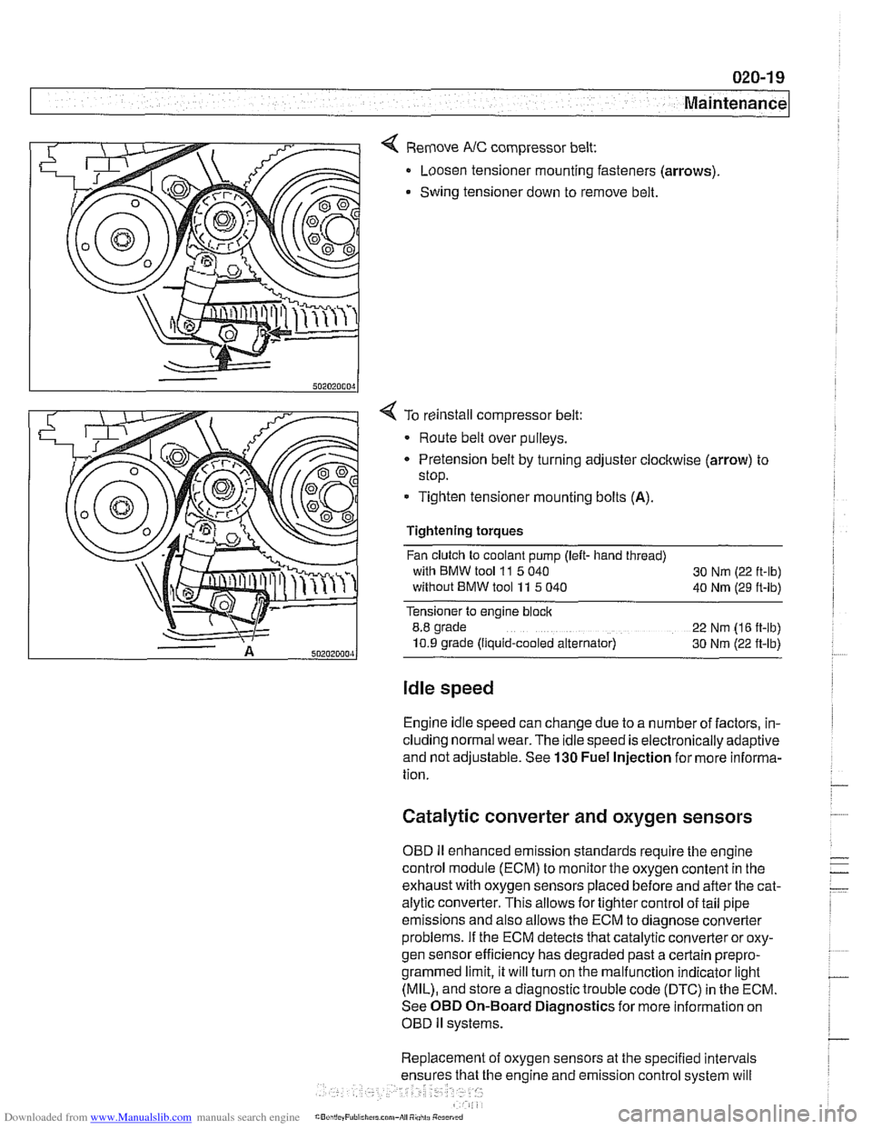
< Remove NC compressor belt:
Loosen tensioner mounting fasteners (arrows)
Swing tensioner down to remove belt.
4 To reinstall compressor belt:
Route belt over pulleys.
* Pretension belt by turning adjuster clockwise (arrow) to
stop.
- Tighten tensioner mounting bolts (A).
Tightening torques
Fan clutch to coolant pump (left- hand thread)
with BMW tool
11 5 040
30 Nm (22 ft-lb)
without BMW tool 11 5 040
40 Nm (29 ft-lb)
Tensioner to engine block
8.8 grade
22 Nm (16 ft-lb)
10.9 grade (Ilquid-cooled alternator) 30 Nm (22 ft-lb)
Idle speed
Engine idle speed can change due to a number of factors, in-
cluding normal wear. The idle speed is electronically adaptive
and not adjustable. See
130 Fuel Injection for more informa-
tion.
Catalytic converter and oxygen sensors
OBD II enhanced emission standards require the engine
control module (ECM) to monitor the oxygen content in the
exhaust with oxygen sensors placed before and after the cat-
alytic converter. This allows for tighter control of tail pipe
emissions and also allows the ECM to diagnose converter
problems. If the ECM detects that catalytic converter or oxy-
gen sensor efficiency has degraded past a certain
prepro-
grammed limit, it will turn on the malfunction indicator light
(MIL), and store a diagnostic trouble code (DTC) in the ECM.
See OBD On-Board Diagnostics for more information on
OBD
ll systems.
Replacement of oxygen sensors at the specified intervals
he engine and emission control system will
Page 64 of 1002

Downloaded from www.Manualslib.com manuals search engine
020-32
Maintenance
using a soft cloth. Regular use of a good quality leather condi-
tioner will reduce drying and cracking of the leather.
Polishing
Use paint polish only if the finish assumes a dull loolc afler
long service. Polish can be used to remove tar spots and tar-
nish, but
afleiwards a coat of waxshould be applied to protect
the clean finish. Do not use abrasive polish or cleaners on
aluminum trim or accessories.
Seat belts
Dirt and other abrasive particles will damage seat belt web-
bing. If it is necessary to clean seat belts, use a mild soap so-
lution. Bleach and other strong cleaning agents may weaken
the belt webbing and should be avoided.
WARNING-
Do not clean the seat belt webbing using dry cleaning or oth-
er chemicals. Allow wet belts to
dry before allowing them to
retract.
-
The condition of the belt webbing and the function of the re-
tractor mechanisms should be inspected. See
720 Seat Belts
for seat belt inspection information.
Speciai cieaning
Tarspots can be removed with a bug and tar remover. Never
use gasoline,
lterosene, nail polish remover, or other unsuit-
able solvents. Insect spots also respond to tar remover.
A bit
of baking soda dissolved in the wash water will facilitate their
removal. This method can also be used to remove tree sap
spots.
Washing chassis
Periodic washing of the underside of the car, especially in
winter, will help prevent accumulation of road salt and rust.
The best time to wash the underside is just afler the car has
been driven in wet conditions. Spray the chassis with a pow-
erful jet of water. Commercial or self-service carwashes may
not be bestforthis, as they may recycle the salt-contaminated
water.
Waxing
For a long-lasting, protective, and glossy finish, apply a hard
wax after the car has been washed and dried. Use carnauba
or synthetic based products. Waxing is not needed after
every washing. You can tell when waxing is required by
look-
Page 84 of 1002
Downloaded from www.Manualslib.com manuals search engine
110-12
Engine Removal and Installation
4 Remove hoses from thermostat housing by releasing locks
(arrows). If applicable, detach electrical harness connector
for thermostat housing.
NOTE-
Two different types of hose fasteners are used on the E39
car; lock clamp type as shown above or standard band
clamps.
- On vehicles equipped with mechanical cooling fan: Remove
belt-driven cooling fan and radiator as described in
170 Ra-
diator and Cooling
System.
CAUTION-
32 mm radiator fan mounting nut has left hand threads.
4 Disconnect coolant hose (arrow) at rear left side of engine
above starter.
4 Disconnect coolant hose (arrow) at front left side of engine
mount.
- Unbolt power steering fluid reservoir and pull aside without
detaching hoses. Secure to fender with cord or stiff wire.
Page 85 of 1002

Downloaded from www.Manualslib.com manuals search engine
Engine Removal and Installation
4 Working at E-box at right rear of engine compartment:
Disconnect engine electrical harness connectors
(arrows).
Lift off harness looms and lay over engine.
- Remove polyribbed drive belts. Mark direction of rotation if
belts will be reused. See 020 Maintenance.
- Remove exhaust system and transmission from car. See 180
Exhaust System, 230 Manual Transmission or 240 Auto-
matic Transmission.
NOJE-
Detach automatic transmission cooler lines from radiator, re-
move brackets holding lines to side of engine, andstore lines
in a clean environment.
- Remove power steering pump:
If necessary, remove steering pump pulley.
Remove front and rear pump mounting bolts.
Suspend pump from body using stiff wire.
4 Remove A/C compressor mounting bolts (arrows) and AIC
compressor from its mounting bracketwithoutdisconnecting,
distorting, or deforming any refrigerant lines. Suspend from
body using stiff wire.
4 If applicable, remove secondary air pump:
Remove hose at one-way valve
(A).
Remove bolts at support bracket on strut tower (arrows).
- Disconnect electrical harness from bottom of secondary
air pump.
Remove bracket from strut tower.
Page 87 of 1002

Downloaded from www.Manualslib.com manuals search engine
110-15
Engine Removal and lnstallation
- Installation is reverse of removal, noting the following:
Replace all gaskets. O-rings and seals.
Use new fuel injector seals
Check that engine drive belts properly engage pulley
grooves.
Inspect O-ring seal between mass air flow sensor and air
filter housing. To facilitate reassembly, coat seal with acid-
free grease.
Change engine oil and filter and
check all other fluid levels.
See
020 Maintenance.
Refill and bleed cooling system. See
170 Radiator and
Cooling System.
CAUTION--
When reattaching throttle assembly harness connectoc con-
nector is
fuNy tightened when arrows on connector and plug
line up.
Tightening torques
Coolant drain plug to cylinder block
25 Nm (18 ft-lb)
Engine mount to
subframe (M10) 45 Nm (33 ft-ib)
Exhaust manifold to cylinder head
M6 10 Nm (89 in-lb)
M7 or ME 20 Nm (15 ft-lb)
Intake manifold to cylinder head
M7 15 Nm (I 1 ft-lb)
ME 22 Nm (16 ft-lb)
Radiator cooling fan to coolant pump
40 Nm (30 ft-lb)
Radiator drain screw to radiator
2.5 Nm (22 in-lb)
Page 92 of 1002

Downloaded from www.Manualslib.com manuals search engine
11 0-20
Engine Removal and Installation
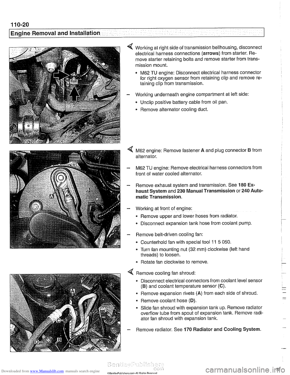
Working at right side of transmission bellhousing, disconnect
electrical harness connections (arrows) from starter. Re-
move starter retaining bolts and remove starter from trans-
mission mount.
M62 TU engine: Disconnect electrical harness connector
for right oxygen sensor from retaining clip and remove re-
taining clip from transmission.
- Working underneath engine compartment at left side:
Unclip positive battery cable from oil pan.
. Remove alternator cooling duct.
4 M62 engine: Remove fastener A and plug connector B from
alternator.
- M62 TU engine: Remove electrical harness connectors from
front of water cooled alternator.
- Remove exhaust system and transmission. See 180 Ex-
haust System and 230 Manual Transmission or 240 Auto-
matic Transmission.
- Working at front of engine:
Remove upper and lower hoses from radiator.
D~sconnect expansion tank hose from coolant pump.
- Remove belt-driven cooling fan:
Counterhold fan with special tool
11 5 050.
Turn fan mounting nut (32 mm) clockwise (left hand
threads) to loosen.
Rotate fan clockwise to remove.
Remove cooling fan shroud:
Disconnect electrical connectors from coolant level sensor
(B) and coolant temperature sensor (C).
. Remove expansion rivets (A) from each side of shroud
Remove coolant hose
(D).
Slide fan shroud with expansion tank up. Remove radiator
overflow tube from spout of expansion tank. Remove radi-
ator fan shroud with expansion tank.
Remove radiator. See
170 Radiator and Cooling System.