Page 27 of 72
28
SSP 198/05
Engine
Divert air control in overrun
To avoid pumping the exhaust gas
turbochargers when a sudden transition from
high load to overrun is made, two divert air
valves are used.
The Motronic also activates the
two pneumatic divert air valves by
means of
an
electrical changeover
valve, the divert air valve for
turbocharger N249.
Advantage:
•
Controlled opening of the
divert air valves reduces the
noise level in the induction
tract and reduces fuel
consumption.
The divert air valve N249, in combination with
the vacuum reservoir, enables the divert air
valves to operate independently of the intake
manifold pressure.
The system is designed in such a way that the
pneumatic divert air valves continue to be
opened by the intake manifold pressure if the
electrically actuated divert air valve N249 fails.
Divert air valve for turbocharger N249
Vacuum reservoir (inside
wheelhousing on the left)
Divert air valve (pneumatic)
with flow
without flow
Non-return valve
Page 28 of 72
29
SSP 198/06
Vacuum in intake manifold:
Non-return valve 1 open. Fuel vapours return
to intake manifold.
charge pressure in intake manifold:
Non-return valve 2 open. Fuel vapours return
upstream of exhaust gas turbocharger.
ACF system
Integrated in the lines of the ACF systems are
the solenoid valve for activated charcoal
canister N80 and two non-return valves.
The engine control unit, assisted by solenoid
valve N80, regulates the return rate of the fuel
vapours from the ACF canister.
The Motronic operates the solenoid valve
cyclically using a pulse duty cycle.
The non-return valves control the return of fuel
vapours, depending on operating state.
ACF canister
Solenoid valve for activa-
ted charcoal canister N80
Non-return valve 2Non-return valve 1
Vacuum in intake manifold
Charge pressure in intake manifold
For the exact line routing, please refer
to the Workshop Manual.
Page 29 of 72

30
SSP 198/07
Engine
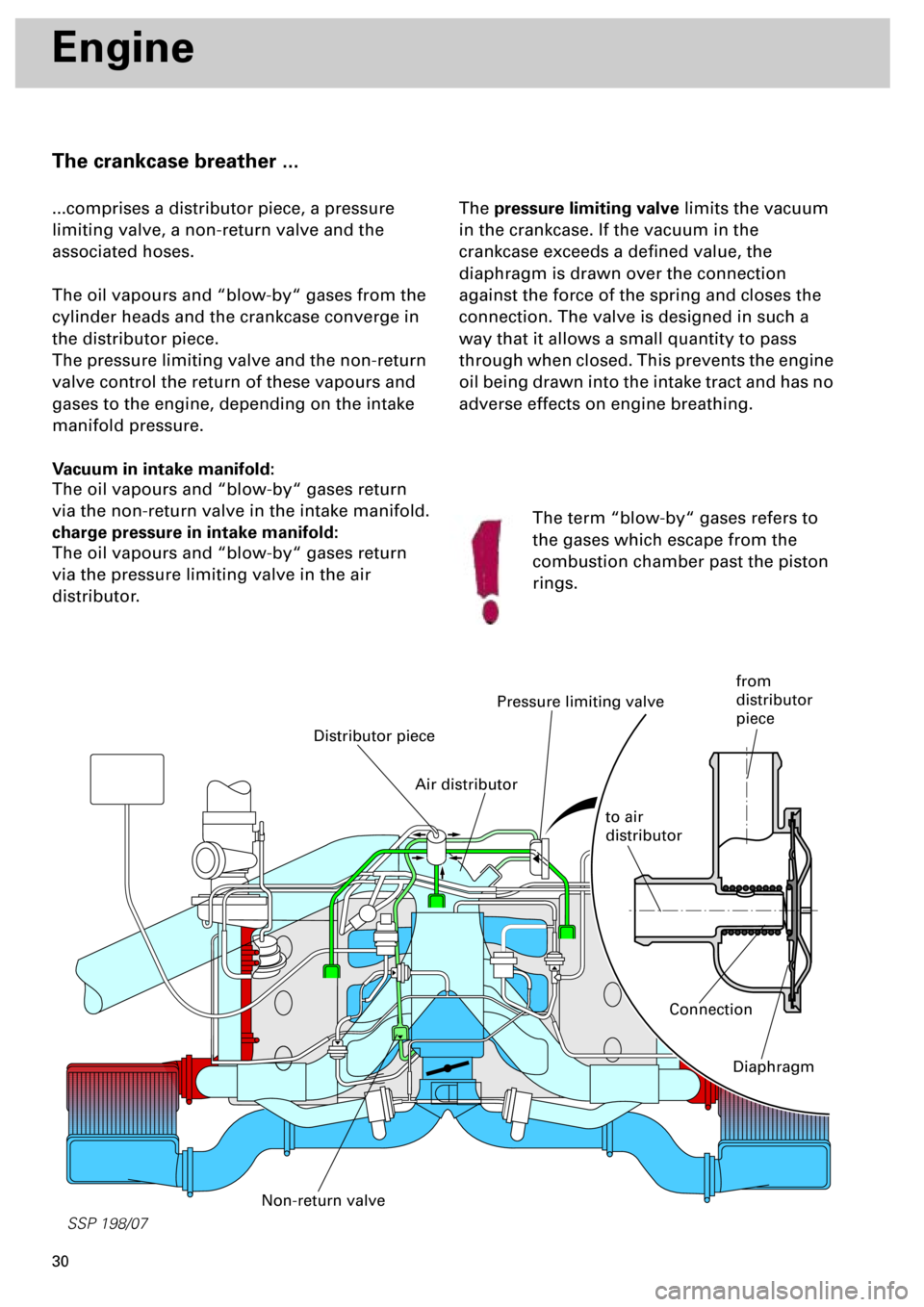
The crankcase breather ...
...comprises a distributor piece, a pressure
limiting valve, a non-return valve and the
associated hoses.
The oil vapours and “blow-by“ gases from the
cylinder heads and the crankcase converge in
the distributor piece.
The pressure limiting valve and the non-return
valve control the return of these vapours and
gases to the engine, depending on the intake
manifold pressure.
Vacuum in intake manifold:
The oil vapours and “blow-by“ gases return
via the non-return valve in the intake manifold.
charge pressure in intake manifold:
The oil vapours and “blow-by“ gases return
via the pressure limiting valve in the air
distributor.The pressure limiting valve limits the vacuum
in the crankcase. If the vacuum in the
crankcase exceeds a defined value, the
diaphragm is drawn over the connection
against the force of the spring and closes the
connection. The valve is designed in such a
way that it allows a small quantity to pass
through when closed. This prevents the engine
oil being drawn into the intake tract and has no
adverse effects on engine breathing.
Distributor piece
Pressure limiting valve
Non-return valve
The term “blow-by“ gases refers to
the gases which escape from the
combustion chamber past the piston
rings.
Connection
Diaphragm
Air distributor
to air
distributor
from
distributor
piece
Page 30 of 72
31
Motronic ME 7.1
Subfunctions of the Motronic
The Motronic consists of known and new subfunctions:
Sequential injection
Charge pressure control
(see chapter on “Engine” pp. 26 and 27)
Stereo lambda control
Mapped ignition
Cylinder-selective knock control
Static high-tension distribution with 6 individual ignition coils
ACF system
Torque-oriented engine management
Electrically actuated throttle valve (Electronic accelerator)
Cylinder bank-specific exhaust gas temperature control
Mapped variable valve timing (intake camshaft adjustment)
(see chapter on “Engine” p. 8)
New
New
New
New
l
SSP 198/44
Page 31 of 72

32
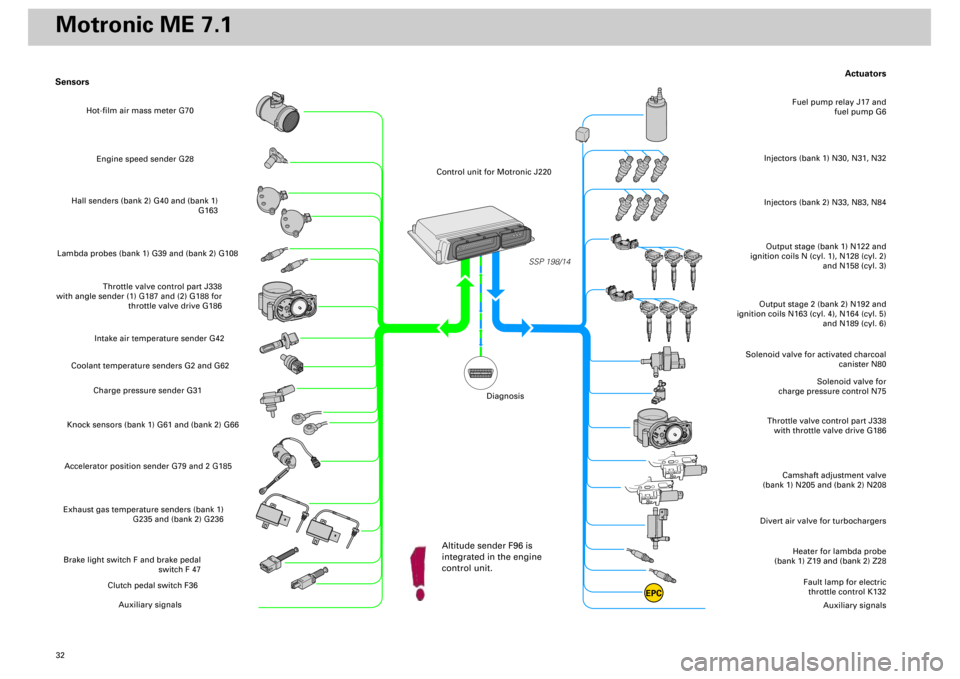
Actuators
Heater for lambda probe
(bank 1) Z19 and (bank 2) Z28
Divert air valve for turbochargers
Camshaft adjustment valve
(bank 1) N205 and (bank 2) N208
Throttle valve control part J338
with throttle valve drive G186
Solenoid valve for
charge pressure control N75
Solenoid valve for activated charcoal
canister N80
Output stage (bank 1) N122 and
ignition coils N (cyl. 1), N128 (cyl. 2)
and N158 (cyl. 3)Injectors (bank 1) N30, N31, N32
Fuel pump relay J17 and
fuel pump G6
Output stage 2 (bank 2) N192 and
ignition coils N163 (cyl. 4), N164 (cyl. 5)
and N189 (cyl. 6)
Fault lamp for electric
throttle control K132
Auxiliary signals
Sensors
Engine speed sender G28
Hall senders (bank 2) G40 and (bank 1)
G163
Lambda probes (bank 1) G39 and (bank 2) G108
Throttle valve control part J338
with angle sender (1) G187 and (2) G188 for
throttle valve drive G186
Intake air temperature sender G42
Coolant temperature senders G2 and G62
Charge pressure sender G31
Knock sensors (bank 1) G61 and (bank 2) G66Accelerator position sender G79 and 2 G185Exhaust gas temperature senders (bank 1)
G235 and (bank 2) G236Brake light switch F and brake pedal
switch F 47
Clutch pedal switch F36
Auxiliary signals
SSP 198/14
EPC
Injectors (bank 2) N33, N83, N84
Hot-film air mass meter G70
Control unit for Motronic J220
Altitude sender F96 is
integrated in the engine
control unit.
Diagnosis
Motronic ME 7.1
Page 32 of 72
33
SSP/198/15
Subsystems of the Motronic
Making allowance for efficiency and the
emissions standards, the engine control unit
coordinates the external and internal requests
and meets them by adjusting the available
control variables accordingly.
Torque-oriented engine
management
The Motronic ME 7.1 has a torque-
oriented functional structure.
This is made possible by the new
electronic accelerator function.
Internal torque requests
External torque requests
• Starting
• Idling speed control
• Catalytic converter
heating
• Power limiter
• Driving comfort
• Components
protection
• Engine governing
• Driver inputs
Throttle valve
angle
Charge pressure
Ignition angle
Injection cut-out
Injection time
Control variables
influencing torque
• Driving
dynamics
• Driving
comfort
• Cruise control
system
Coordination of
torque and
efficiency requests
in engine control
unit
Page 35 of 72

36
SSP 198/09
Subsystems of the Motronic
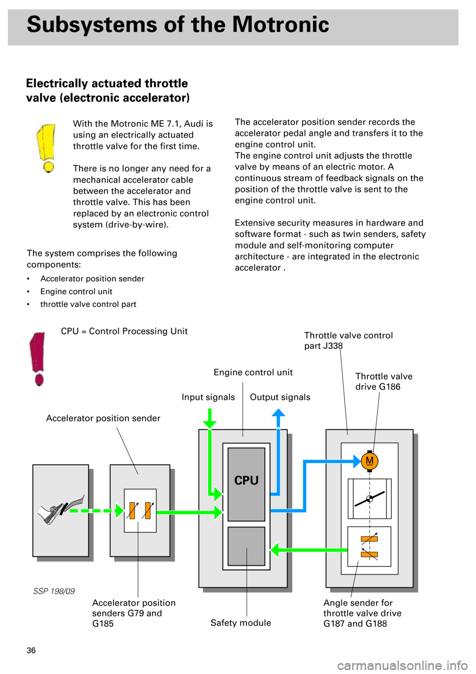
Electrically actuated throttle
valve (electronic accelerator)
With the Motronic ME 7.1, Audi is
using an electrically actuated
throttle valve for the first time.
There is no longer any need for a
mechanical accelerator cable
between the accelerator and
throttle valve. This has been
replaced by an electronic control
system (drive-by-wire).
The system comprises the following
components:
• Accelerator position sender
• Engine control unit
• throttle valve control part
Accelerator position sender
Safety module
Throttle valve control
part J338
The accelerator position sender records the
accelerator pedal angle and transfers it to the
engine control unit.
The engine control unit adjusts the throttle
valve by means of an electric motor. A
continuous stream of feedback signals on the
position of the throttle valve is sent to the
engine control unit.
Extensive security measures in hardware and
software format - such as twin senders, safety
module and self-monitoring computer
architecture - are integrated in the electronic
accelerator .
Input signalsOutput signals
Angle sender for
throttle valve drive
G187 and G188Accelerator position
senders G79 and
G185
Engine control unit
CPU
CPU = Control Processing Unit
Throttle valve
drive G186
Page 36 of 72

37
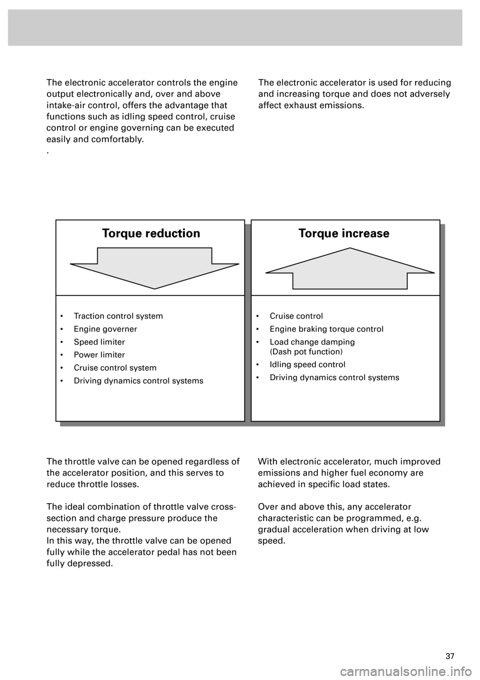
The electronic accelerator controls the engine
output electronically and, over and above
intake-air control, offers the advantage that
functions such as idling speed control, cruise
control or engine governing can be executed
easily and comfortably.
.
The throttle valve can be opened regardless of
the accelerator position, and this serves to
reduce throttle losses.
The ideal combination of throttle valve cross-
section and charge pressure produce the
necessary torque.
In this way, the throttle valve can be opened
fully while the accelerator pedal has not been
fully depressed.With electronic accelerator, much improved
emissions and higher fuel economy are
achieved in specific load states.
Over and above this, any accelerator
characteristic can be programmed, e.g.
gradual acceleration when driving at low
speed.
The electronic accelerator is used for reducing
and increasing torque and does not adversely
affect exhaust emissions.
• Traction control system
• Engine governer
• Speed limiter
• Power limiter
• Cruise control system
• Driving dynamics control systems
Torque reduction
Torque increase
• Cruise control
• Engine braking torque control
• Load change damping
(Dash pot function)
• Idling speed control
• Driving dynamics control systems