Page 66 of 72

67
Problem:
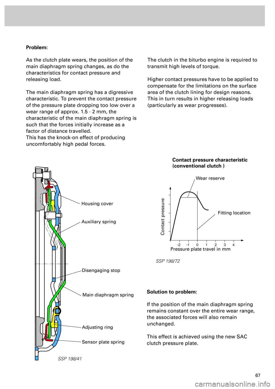
As the clutch plate wears, the position of the
main diaphragm spring changes, as do the
characteristics for contact pressure and
releasing load.
The main diaphragm spring has a digressive
characteristic. To prevent the contact pressure
of the pressure plate dropping too low over a
wear range of approx. 1.5 - 2 mm, the
characteristic of the main diaphragm spring is
such that the forces initially increase as a
factor of distance travelled.
This has the knock-on effect of producing
uncomfortably high pedal forces.
The clutch in the biturbo engine is required to
transmit high levels of torque.
Higher contact pressures have to be applied to
compensate for the limitations on the surface
area of the clutch lining for design reasons.
This in turn results in higher releasing loads
(particularly as wear progresses).
Solution to problem:
If the position of the main diaphragm spring
remains constant over the entire wear range,
the associated forces will also remain
unchanged.
This effect is achieved using the new SAC
clutch pressure plate.
SSP 198/41
Housing cover
SSP 198/72
0 -1 -2 1 2 3 4
Pressure plate travel in mm
Contact pressure
Fitting location
Wear reserve
Contact pressure characteristic
(conventional clutch )
Sensor plate spring
Main diaphragm spring
Adjusting ring
Auxiliary spring
Disengaging stop
Page 67 of 72
68
Power Transmission
Function of SAC clutch
Compared to a conventional clutch, the
following parts are new or modified:
• Sensor plate spring
• Adjusting ring with ramps (wedges) and
compression springs
• Housing cover with ramp indentations and
guides for the compression springs
• Stop for release travel (integrated in the
housing cover)
• Auxiliary spring (riveted to the housing
cover)The
stop for release travel
limits the
travel of the release bearing and
prevents unintentional adjustment of
the adjusting ring.
The
auxiliary spring
counteracts the
main plate spring as of a defined
travel distance and ensures an even
force curve during clutch engagement
and disengagement.
SSP 198/70
Housing cover with auxiliary spring
and s
top for release travel
Main diaphragm spring
Pressure plate
Auxiliary spring
(riveted on)
Sensor plate spring
Adjusting ring with
compression springs
Page 68 of 72
69
Unlike conventional pressure plates, the main
diaphragm spring mounting of the SAC clutch
is non-rigid.
When the clutch plate is renewed, the
adjusting ring must be turned back
(refer to Workshop Manual).
The adjusting ring on new SAC clutch
pressure plates is already reset.
The sensor plate spring and the adjusting ring
locate (mounting) the main diaphragm spring.
SSP 198/73
after wear
after wear
Position as newPosition after
wearPosition as newPosition after
wear
Main plate
spring mounting
Main plate
spring mounting
Conventional clutch
SAC clutch
Adjusting ring
Page 69 of 72
70
Power transmission
Clutch disengagement process
The force of the sensor plate spring
counteracts that of the main diaphragm spring
and is rated such that the main diaphragm
spring is pressed against the adjusting ring
under normal releasing load.
If the force of the main diaphragm spring (also
refer to load diagram) is greater than that of
the sensor plate spring, the main plate spring
will not come into contact with the adjusting
ring.
The compression springs rotate the adjusting
ring along the ramps in the housing cover.
In this way, lining wear is compensated and
the forces are again equalised.
SSP 198/74
Main diaphragm spring
Sensor plate springHousing cover
Adjusting ring with ramps
Compress. spring
Compression spring
Main
diaphragm
spring
mounting
Ramp (wedge)
after wear
as new
Page:
< prev 1-8 9-16 17-24