Page 30 of 72
31
Motronic ME 7.1
Subfunctions of the Motronic
The Motronic consists of known and new subfunctions:
Sequential injection
Charge pressure control
(see chapter on “Engine” pp. 26 and 27)
Stereo lambda control
Mapped ignition
Cylinder-selective knock control
Static high-tension distribution with 6 individual ignition coils
ACF system
Torque-oriented engine management
Electrically actuated throttle valve (Electronic accelerator)
Cylinder bank-specific exhaust gas temperature control
Mapped variable valve timing (intake camshaft adjustment)
(see chapter on “Engine” p. 8)
New
New
New
New
l
SSP 198/44
Page 31 of 72

32
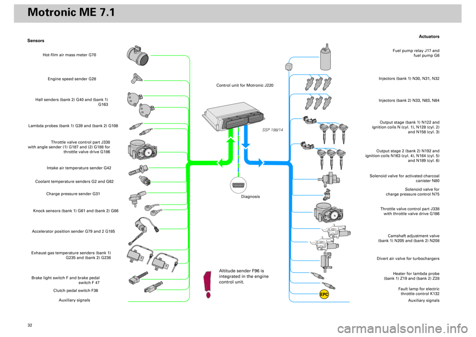
Actuators
Heater for lambda probe
(bank 1) Z19 and (bank 2) Z28
Divert air valve for turbochargers
Camshaft adjustment valve
(bank 1) N205 and (bank 2) N208
Throttle valve control part J338
with throttle valve drive G186
Solenoid valve for
charge pressure control N75
Solenoid valve for activated charcoal
canister N80
Output stage (bank 1) N122 and
ignition coils N (cyl. 1), N128 (cyl. 2)
and N158 (cyl. 3)Injectors (bank 1) N30, N31, N32
Fuel pump relay J17 and
fuel pump G6
Output stage 2 (bank 2) N192 and
ignition coils N163 (cyl. 4), N164 (cyl. 5)
and N189 (cyl. 6)
Fault lamp for electric
throttle control K132
Auxiliary signals
Sensors
Engine speed sender G28
Hall senders (bank 2) G40 and (bank 1)
G163
Lambda probes (bank 1) G39 and (bank 2) G108
Throttle valve control part J338
with angle sender (1) G187 and (2) G188 for
throttle valve drive G186
Intake air temperature sender G42
Coolant temperature senders G2 and G62
Charge pressure sender G31
Knock sensors (bank 1) G61 and (bank 2) G66Accelerator position sender G79 and 2 G185Exhaust gas temperature senders (bank 1)
G235 and (bank 2) G236Brake light switch F and brake pedal
switch F 47
Clutch pedal switch F36
Auxiliary signals
SSP 198/14
EPC
Injectors (bank 2) N33, N83, N84
Hot-film air mass meter G70
Control unit for Motronic J220
Altitude sender F96 is
integrated in the engine
control unit.
Diagnosis
Motronic ME 7.1
Page 61 of 72

62
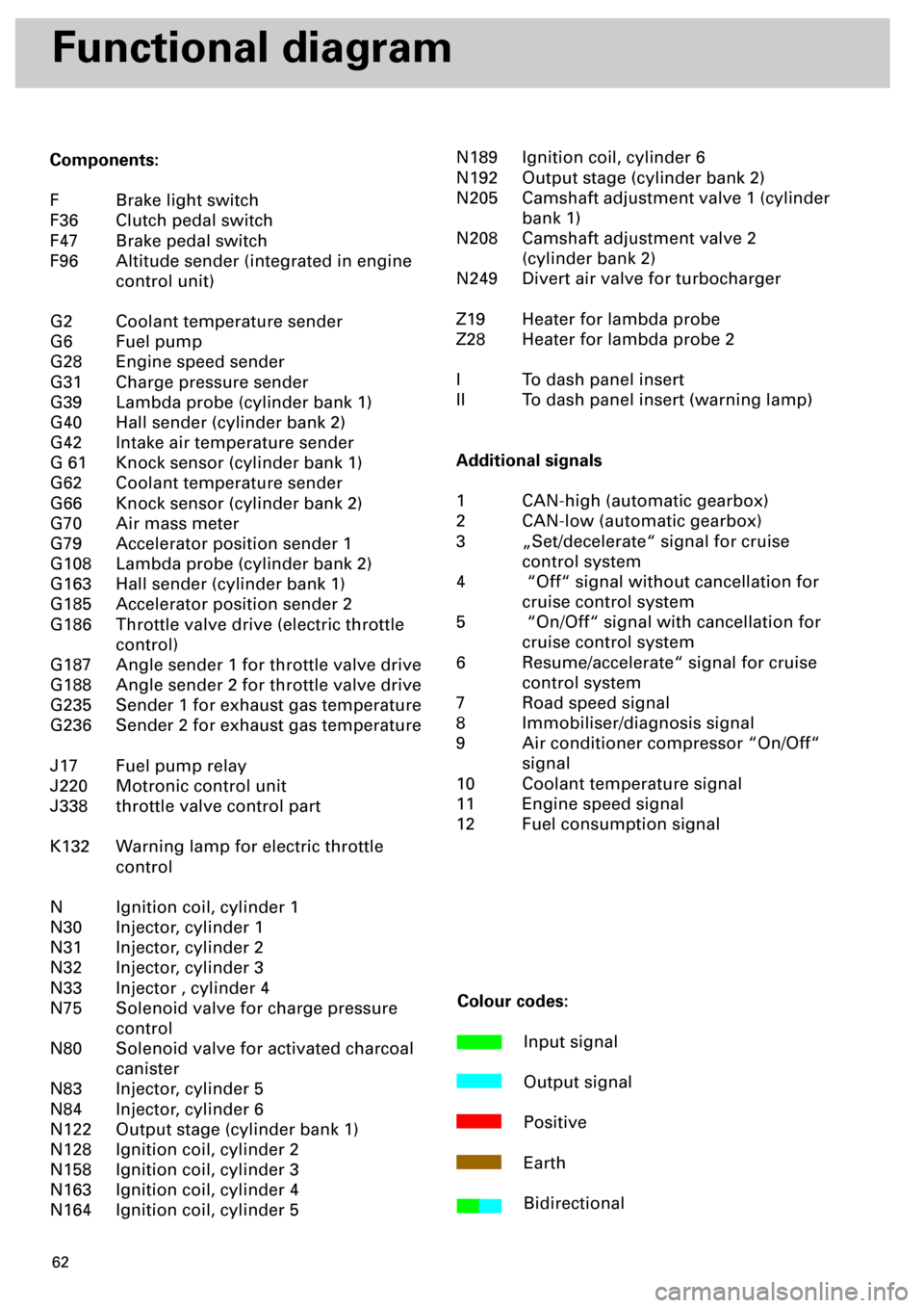
Functional diagram
Components:
F Brake light switch
F36 Clutch pedal switch
F47 Brake pedal switch
F96 Altitude sender (integrated in engine
control unit)
G2 Coolant temperature sender
G6 Fuel pump
G28 Engine speed sender
G31 Charge pressure sender
G39 Lambda probe (cylinder bank 1)
G40 Hall sender (cylinder bank 2)
G42 Intake air temperature sender
G 61 Knock sensor (cylinder bank 1)
G62 Coolant temperature sender
G66 Knock sensor (cylinder bank 2)
G70 Air mass meter
G79 Accelerator position sender 1
G108 Lambda probe (cylinder bank 2)
G163 Hall sender (cylinder bank 1)
G185 Accelerator position sender 2
G186 Throttle valve drive (electric throttle
control)
G187 Angle sender 1 for throttle valve drive
G188 Angle sender 2 for throttle valve drive
G235 Sender 1 for exhaust gas temperature
G236 Sender 2 for exhaust gas temperature
J17 Fuel pump relay
J220 Motronic control unit
J338 throttle valve control part
K132 Warning lamp for electric throttle
control
N Ignition coil, cylinder 1
N30 Injector, cylinder 1
N31 Injector, cylinder 2
N32 Injector, cylinder 3
N33 Injector , cylinder 4
N75 Solenoid valve for charge pressure
control
N80 Solenoid valve for activated charcoal
canister
N83 Injector, cylinder 5
N84 Injector, cylinder 6
N122 Output stage (cylinder bank 1)
N128 Ignition coil, cylinder 2
N158 Ignition coil, cylinder 3
N163 Ignition coil, cylinder 4
N164 Ignition coil, cylinder 5N189 Ignition coil, cylinder 6
N192 Output stage (cylinder bank 2)
N205 Camshaft adjustment valve 1 (cylinder
bank 1)
N208 Camshaft adjustment valve 2
(cylinder bank 2)
N249 Divert air valve for turbocharger
Z19 Heater for lambda probe
Z28 Heater for lambda probe 2
I To dash panel insert
II To dash panel insert (warning lamp)
Additional signals
1 CAN-high (automatic gearbox)
2 CAN-low (automatic gearbox)
3 „Set/decelerate“ signal for cruise
control system
4 “Off“ signal without cancellation for
cruise control system
5 “On/Off“ signal with cancellation for
cruise control system
6 Resume/accelerate“ signal for cruise
control system
7 Road speed signal
8 Immobiliser/diagnosis signal
9 Air conditioner compressor “On/Off“
signal
10 Coolant temperature signal
11 Engine speed signal
12 Fuel consumption signal
Colour codes:
Input signal
Output signal
Positive
Earth
Bidirectional
Page 70 of 72
71
Gearbox
In the S4, power is transmitted through the
already familiar 6-speed Quattro manual
gearbox of type 01E (C90 gearbox).
As is normal with Audi’s high-performance
models, the gearbox oil is cooled by an oil
pump and an oil cooler.
The
Audi A6
with biturbo engine can be
combined with the following gearbox versions
at the customer’s option:
Front-wheel drive Manual gearbox 01E (without oil cooling)
Quattro drive Manual gearbox 01E (without oil cooling
Front-wheel drive Automatic gearbox 01V
Quattro drive Automatic gearbox 01V
Due to the two mass flywheel in
combination with the SAC clutch, a
new 11 mm-thick spacer ring is used
for the manual gearboxes in
between the engine and gearbox.
SSP 198/76
to oil cooler
Oil pump