Page 4 of 81

24-3
Rules of cleanliness
When working on the fuel supply or fuel injection
systems, the following "6 rules of cleanliness"
should be carefully observed:
Thoroughly clean all connections and the
surrounding area before disconnecting.
Place parts that have been removed on a clean
surface and cover. Use lint-free cloths only!
Carefully cover over opened components or
seal, if repairs are not carried out immediately.
Only install clean components:Only unpack
replacement parts immediately prior to
installation. Do not use parts that have been
stored loose (in tool boxes etc.)
When the system is open:Do not work with
compressed air if it can be avoided. Do not
move vehicle unless absolutely necessary.
Disconnected electrical harness
connectors:Protect from dirt and moisture. Be
sure harness connector is dry before
connecting.
Pa
ge 4 of 81 Motronic fuel in
jection s
ystem, servicin
g
11/21/2002 htt
p://127.0.0.1:8080/audi/servlet/Dis
play?action=Goto&t
yp
e=re
pair&id=AUDI.B5.FU06.24.1
Page 15 of 81
24-14
Note:
In order to assure sufficiently secure fitting, switches must not be installed
more than once.
Adjusting switch:
Repair Manual, Brake System, Repair Group 46, Brake booster, removing and installing
Fig. 3 Installation location of brake light switch -F- and brake
pedal switch -F47-, clutch vacuum vent valve switch -F36-
1 - Clip
2 - Clutch vacuum vent valve switch -F36-
3 - Brake light switch -F-, brake pedal switch -F47-
Note:
Illustration depicts intake manifold removed, from below. Fig. 4 Installation location of Secondary Air Injection (AIR)
solenoid valve-N112- and recirculating valve for
turbocharger-N249-
Installation location: Below intake manifold
1 - Recirculating valve for turbocharger -N249-
2 - Secondary Air Injection (AIR) solenoid valve -N112-
Pa
ge 15 of 81 Motronic fuel in
jection s
ystem, servicin
g
11/21/2002 htt
p://127.0.0.1:8080/audi/servlet/Dis
play?action=Goto&t
yp
e=re
pair&id=AUDI.B5.FU06.24.1
Page 21 of 81
24-20
Special tools and equipment
Procedure
VAG1598/31
- Switch ignition off.
- Remove Engine Control Module (ECM) Page 24
-23
.
- Connect VAG1598/31 test box to connector of wiring harness. Ground
(GND) clip at test box (not visible in illustration) must be connected to
Ground (GND). Relevant test procedures note whether Engine Control
Module (ECM) should also be connected to the test box.
- Perform test as described in relevant repair sequence.
Pa
ge 21 of 81 Motronic fuel in
jection s
ystem, servicin
g
11/21/2002 htt
p://127.0.0.1:8080/audi/servlet/Dis
play?action=Goto&t
yp
e=re
pair&id=AUDI.B5.FU06.24.1
Page 25 of 81
24-24
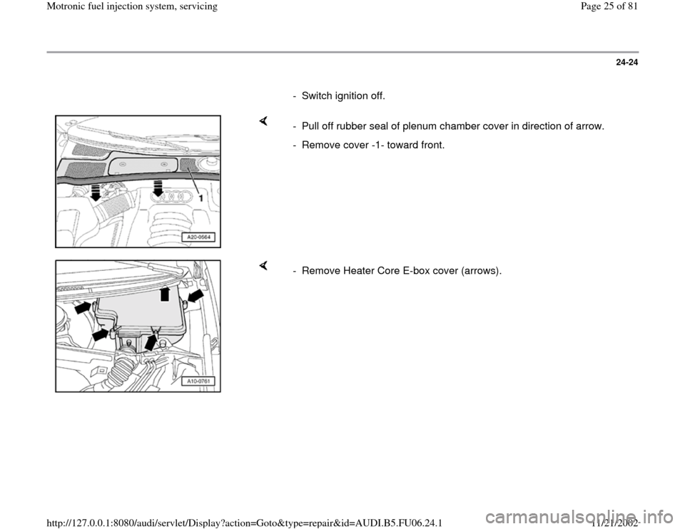
- Switch ignition off.
- Pull off rubber seal of plenum chamber cover in direction of arrow.
- Remove cover -1- toward front.
- Remove Heater Core E-box cover (arrows).
Pa
ge 25 of 81 Motronic fuel in
jection s
ystem, servicin
g
11/21/2002 htt
p://127.0.0.1:8080/audi/servlet/Dis
play?action=Goto&t
yp
e=re
pair&id=AUDI.B5.FU06.24.1
Page 26 of 81
24-25
- Using a screwdriver, carefully pry off retaining bracket (arrow).
Note:
Adaptation values are erased when connector is disconnected from the
Engine Control Module (ECM), DTC memory content remains intact. - Disengage connector catches (arrows) and disconnect harness
connectors -1- and -2- from control module.
- Remove Engine Control Module (ECM).
Pa
ge 26 of 81 Motronic fuel in
jection s
ystem, servicin
g
11/21/2002 htt
p://127.0.0.1:8080/audi/servlet/Dis
play?action=Goto&t
yp
e=re
pair&id=AUDI.B5.FU06.24.1
Page 38 of 81
24-34
Checking system pressure
- Open fuel filler flap briefly (pressure release).
WARNING!
Fuel system is under pressure! Before opening system, place rags
around the connection point. Then release pressure by carefully
loosening connection. - Remove engine cover (arrows).
- Open threaded connection (arrow) and catch exiting fuel using a rag.
- Connect VAG1318 pressure gauge in supply line using adapters
1318/11, 1318/12 and 1318/13.
Pa
ge 38 of 81 Motronic fuel in
jection s
ystem, servicin
g
11/21/2002 htt
p://127.0.0.1:8080/audi/servlet/Dis
play?action=Goto&t
yp
e=re
pair&id=AUDI.B5.FU06.24.1
Page 43 of 81
24-39
Checking internal resistance
- Remove engine cover (arrows).
- Disconnect harness connector at the fuel injector to be tested.
If specified value is not obtained:
If specified value is obtained: - Connect multimeter at valve for resistance measurement.
Specification: 12 to 13 (at room temperature)
- Replace fuel injector.
- Check voltage supply
Pa
ge 43 of 81 Motronic fuel in
jection s
ystem, servicin
g
11/21/2002 htt
p://127.0.0.1:8080/audi/servlet/Dis
play?action=Goto&t
yp
e=re
pair&id=AUDI.B5.FU06.24.1
Page 51 of 81
24-46
Fuel injectors, removing and installing
- Remove engine cover (arrows).
- Disconnect wiring/connectors at:
- Fuel injectors -N30-, -N31-, -N32-, -N33-
- Intake Air Temperature (IAT) sensor -G42-
- Camshaft Position (CMP) sensor 2 -G40-
- Throttle valve control module -J338-
- Remove retaining bolts for fuel supply rail and disconnect vacuum line
at fuel pressure regulator (arrows).
Pa
ge 51 of 81 Motronic fuel in
jection s
ystem, servicin
g
11/21/2002 htt
p://127.0.0.1:8080/audi/servlet/Dis
play?action=Goto&t
yp
e=re
pair&id=AUDI.B5.FU06.24.1