1998 ACURA INTEGRA parke
[x] Cancel search: parkePage 649 of 1680

Steering
Componsnt Location
lndox
*Stooring Wheel
Removal ....
Disassombly/Ro8$.mbly
Disassombly ......
F08$€mbly
Powcr Stosring Gosrbox
R6moval
............................ 17-3
............. 17 -1
................ 17-16
............................. 17_25
17-30
17.31
.......17-21
Sy3tom DGcription
Fluid Flow Disgram
Steering Pump .............. 17-5
Stocring Goarbox ...17.8
Troublorhooting
Gonoral Troubleshooting .............................. 17.10
Noiso lnd Vibration ...... 17-1i[
Fluid Losk3
lnspoction
Installation
Powor Steering Hos6, Lino3
Roplacom€nt .................. 17.34
Powor Steoring Pump
RGplac6montlolpeqtion lnd Adiu3tm6nl
Stoo.ing Operation
Powor A$bi Chock
with v.hiclo Parked
Stcering Linkage 6nd Goarbox
Pump Bolt
17.18
17.18
17.19
17-20
17.35
t7-36
17 -37
r7-39
Inspoction
................... 17.41
Rack Guide Adiustmont ..........................-.-.-. 17 -21
Ffuid Rcplacemont ........17-21
Pump Prc&suro Chock ...,........................,..,..., 17 -22
Fluid Leakage Inrpection ............................... 17-23
Dissssembly
R€aEs€mbly
In3tallation........... 17_58
Ball Joint Boot Replacem.ni ........................ 17-61
17-U
17.49
J ,urrar*TNTAL REsrRArNr sysrEM (sRsr
The Integra SRS includes a driver's airbag located in the steering wheel hub and a passenger's airbag located inthe dashboard above the glove box,
Information necessary to safely service the SRS is included in this Service Manual. ltems marked with an asterisk(*) on the contents page include, or are located near, SRS components. Servicing, dissssembling or replacing
these items will require special pr6cautions and tools, and should therefore be done by an authorized Acura dealer.
. To avoid rondoring ths SRS inoparstivo. which could |rad to parsonal iniury or doath in the ov€nt of ! sev6.o
trontal collision, all SRS sarvice work must be perto.med by an authorizod Acura dsalor.. lmpropor 3orvic€ procadures, including inco[6ql rgmoval and inrtallation of the SRS, could l6ad to pgrsonal
iniury clus€d by unintentional doployment of the airbags,. Do nol bump tho SRS unh, (Xherwise, th6 3ystom may fail in cas€ ol a collision, or the airbags may d€ploy
when ths ignition switch is ON {ll).. All SRS electrical wiring harness€s aro covered with yallow insulation. Related component3 are located in ths
stcaring column. tront con3ol6, dashboard, d.shbolrd lower panel, and in the dashboard above ths glove box.
Do not u3o electrical test oquipm€nt on the3e circuii3.
NOTE: The original radio has a coded theft protection circuit. Be sure to get the customer's code number before- disconn€cting the battery.- removing the No. 47 (7.5 A) fuse from the under-hood fuse/relay box,- removing the radio.
After service, reconnect power to the radio and turn it on. When the word "CODE" is displayed. enter the cus-
tomer's 5-digit code to restore radio operation.
Page 666 of 1680

Inspection and Adjustment
Steering Operation
Place the front wheels in the straight ahead position and
measure the distance the steering wheel can be turned
without moving the front wheels.
ROTATIONAL PLAY: 0 - 10 mm {0 - 0.39 inl
lf the play exceeds the service limit. perform rack guide
adiustment (see page 17-211.
lf the play is still excessive after rack guide adjustment.
inspect the steering linkage and gearbox as described
on the neld page.
Power Assist Check with
Vehicle Parked
Check the power steering fluid level (see page 17-
21) and pump belt tension (see page 17-201.
Start the engine, allow it to idle. and turn the steer
ing wheel from lock-to-lock several times to warm
up the fluid.
Attach a spring scale to the steering wheel. With the
engine idling and the car on a clean. dry floor. pull
the scale as shown and read it as soon as the tires
begin to turn,
4. The scale should read no more than 34 N (3.5 kgf,
7.7 lbf). lf it reads more, check the gearbox and
pump.
ROTATIONAL PLAY
Page 669 of 1680

Rack Guide AdjustmentFluid Replacement
Check the reservoir at regular intervals, and add fluid as
neceSsary.
CAUTION: Use only Genuine Honda Powel Ste€ring
Fluid-V. Using other fluids such as ATF or othor manu-
laclurer's power ste€ring fluid will damag€ the systom.
SYSTEM CAPACIW:
B18Gl ongine:
1.06lit€r (1.12 US. qt,0.93 lmp.qt)
Excopt 8l8Cl ongino:
1.0 lher (r.06 US. qt.0.88 imp.qtl
at disa$ombly
RESERVOIR CAPACITY:
0.,0 liter {0.42 US. qt, 0.35 lmp.qt}
LEVEL LINE
LEVEL LINE
Raise the reservoir and disconnect the return hose
that goes to the oil cooler.
Connect a hose of suitable diameter to the discon-
nected return hose and put the hose end in a suit-
able container.
CAUTION: Take care not to spill thq fluid on lhe
body and parts. Wipe off any spilled fluid al onc€.
Start the engine. let it run at idle, and turn the steer-
ing wheel from lock-to-lock several times. When
fluid stops running out of the hose, shut off the
engine. Discard the fluid.
2.
RETURN HOSE{From the oilcooler)
4. Reinstallthe return hose on the reservoir.
5. Fill the reservoir to the uDDer level line.
6. Start the engine and run it at fast idle, then turn the
steering from lock-to-lock several times to bleed air
from the system,
7. Recheck the fluid level and add some it necessary.
CAUTION: Do not lill the reservoir boyond thc
upper level line.
J.
4.
NOTE: Perform rack guide adjustment with the wheels
in the straight ahead position.
1. Loosen the rack guide screw locknut with the spe-
cialtool, then loosen the rack guide screw.
Tighten the rack guide screw until it compresses the
spring and seats against the rack guide, then loosen
it.
Retighten ihe rack guide screw to 3.9 N.m (0.4
kgf.m, 2.9 lbi.ft), then back it ofl to specified angle.
Speciliad Roturn Anglo: 20' Max
Tighten th€ locknut while holding the rack guide
screw.
RACK GUIDE SCREW
25Nm{2.5 kgf.m, 18 lbf ft)
LOCKNUT WRENCH. ilo mm079't 6 - SA50001
E
6.
Check for tight or loose steering through the com-
plete turning travel.
Perform following inspections:
. Steering operation (see page 17-18).
a Power assist with car parked.
I
Page 1193 of 1680
t
{)
)
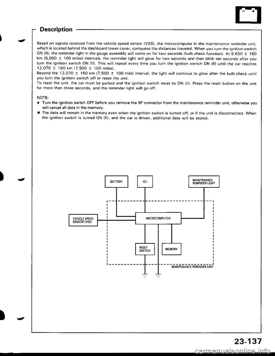
Based on signals received from the vehicle speed sensor (VSS). the microcomputer in the maintenance reminder unit,which is located behind the dashboard lower cover, computes the distances traveled. When you turn the ignition switchON (ll), the reminder light in the gauge assembly will come on for two seconds (bulb check tunction). At 9,650 1 160km {6,000 1 1O0 miles} intervals, the reminder light will glow for two seconds and then blink ten seconds after you
turn the ignition switch ON (ll). This will repeat every rime you turn the ignition switch ON {ll) until rhe car reaches12,O7O ! 1 60 km (7,500 t 100 miles).
Beyond the 12.o1O ! 160 km (7,5OO t IOO mile) interval, the light will continue to glow after the bulb check untilyou turn the ignition switch otf or reset the unit.
To reset the unit, the car must be parked and the ignition switch must be ON (ll). Press the reset button on the unitfor more than three seconds, and the reminder light will go off.
NOTE:
. Turn the ignition switch OFF before you remove the 5P connector from the maintenance reminder unit, otherwise vouwiil cancel all data in the memory.
a The data will remain in the memory even when the ignition switch is turned off, or if the unit is disconnected. Whenthe ignition switch is turned ON (lll, and the car is driven, additional data will be stored.
{
23-137
Page 1501 of 1680
How the Circuit Works
The maintenance reminder light comes on to
remind the driver that the car is due for
scheduled mainlenance.
The maintenance reminder unit receives a vehicle
speed input from the vehicle speed sensor (VSS)
and uses this inlormation to compute the distance
traveled. For the first 6000 t 1 00 miles (9650 t 160
km) after the maintenance reminder light is reset, it
will come on for two seconds when you turn the
ignition switch to ON (ll) as a bulb check.
Between 6000 1 100 miles (9650 t 160 km) and
7500 t 100 miles (12070 I 160 km) the reminder
light will come on for two seconds when you turn
the ignition switch to ON (ll), and then flash for eight
seconds more.
Beyond 7500 t 100 miles (12070 t l60 km) the
reminder light will stay on when the ignition switch is
in the ON (ll) position until the unit is reset.
To reset the unit, the car must be parked and the
ignition switch in the ON (ll) position. Press the
reset button on the unit and hold it there for more
than three seconds, and the reminder light will
go off.
Refer to the Service Manual (Section 23, Electrical)
for specific tests or troubleshooting procedures.
83-1