1998 ACURA INTEGRA g502
[x] Cancel search: g502Page 1069 of 1680
Connector ldentification and Wire Harness Routing
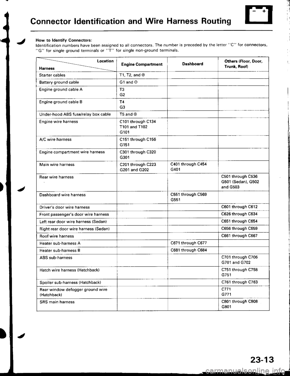
JHow to ldenti{v Connectors:
ldentification numbers have been assigned to all connectors. The number is preceded by the letter "C" for connectors,"G" for single ground terminals ot "f" lor single non-ground terminals.
/
Location
HarnossEngine CompartmentDashboardOthers (Floor, Door,
Trunk. Rooll
Starter cablesT1, T2, and @
Battery ground cableG1 and O
Engine ground cable A
G2
Engine ground cable BT4
G3
Under-hood ABS fuse/relav box cableT5 and @
Engine wire harnessC101 through C134
T101 and T102
G101
A,/C wire harnessC151 through C156
G151
Engine compartment wire harnessC301 through C320
G301
Main wire harnessC201 through C223
G20'l and G202
C40l through C454
G401
Rear wire harnessC501 through C536
G501 (Sedan), G502
and G503
Dashboard wire harnessC551 through C569
G551
Driver's door wire harnessC601 through C612
Front passenger's door wire harnessC626 through C634
Left rear door wire harness (Sedan)C65l through C654
Right rear door wire harness (SedanlC656 throughc659
Roof wire harnessC661 through C667
Heater sub-harness AC671 through C677
Heater sub-harness BC68l through C684
ABS sub-harnessC701 through C706
G701 and G702
Hatch wire harness (Hatchback)C751 through C758
Spoiler sub-harness {Hatchback)C761 through C763
Rear window defogger ground wire
(Hatchback)
c11 l
G77'l
SRS main harnessC801 through C808
G801
23-13
Page 1086 of 1680
Connector ldentification and Wire Harness Routing
Connector or
Terminal
Numbel of
CavitiesLocationConnects toNotes
c501
c502
c503
c504
c505
c506
c507
c508
c509
c5l0
c511
c512
c513
c514
c515
c517
c518
c519
c520
c521
c522
c523
c527
c528
c529
c530
c531
c532
c533
c534
c535
cs36
14
8
14
2
1
1
8
3
1
2
2
1
20
20
3
2
6
4
2
4
6
6
1
1
2
1
1
4
2
4
Behind left kick panel
Behind left kick panel
Behind dashboard lower cover
Behind dashboard lower cover
Behind dashboard lower cover
Driver's door
Center floor
Center floor
Left B-pillar
Fuel tank
Fuel tank
Right B pillar
Above right side of trunk
Above left side of trunk
Left quarter panel| .{+ ^',rrrar ^rnal
Left quarter panel
Left side corner of trunk
Above center of trunk
Left side corner of trunk
Left rear corner of trunk
Right rear corner o{ trunk
Right rear corner ot trunk
Lelt rear door
Right rear door
Left quarter panel
Left side of rear window
Above right side of trunk
Right quarter panel
Right side of rear window
Left side of trunk lid
Center of trunk lid
Right side of trunk lid
lvlain wire harness (C421 )
lvlain wire harness (C422)
Underdash fuse/relay box (C912)
Under dash fuse/relay box (C915)
Dashboard wire harness (C554)
Driver's door wire harness (C6Ol)
Driver's seat belt switch
Parking brake switch
Driver's door switch
Fuel pump
Fuel gauge sending unit
Front passenger's door switch
Right rear speaker
Left rear speaker
Noise condenser
Connector C517
Connector C516
Power antenna motor
Trunk light
Trailer lighting connector
Left outer taillight
License plate lights
Right outer taillight
Lett rear door wire harness
(c651)
Right rear door wire harness
1C656)
Left rear door switch
Rear window defogger {+ )
High mount brake light
Right rear door switch
Rear window detogger (- I
Left inner taillight
Trunk latch switch
Right inner taillight
G501
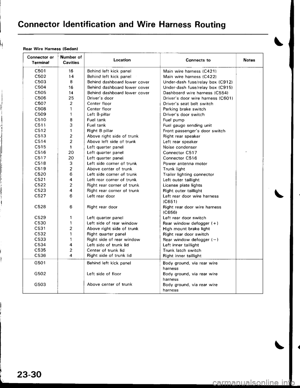
G502
G503
Behind left kick panel
Left side of tloor
Above center of trunk
Body ground, via rear wire
harness
Body ground, via rear wire
harness
Body ground, via rear wire
harness
Rear Wire Hamess {Sedan}
I
ri
I
i
I
li
!
Page 1187 of 1680
)
{
t.t
t.!
23-131
Fuel Gauge
Gauge Test
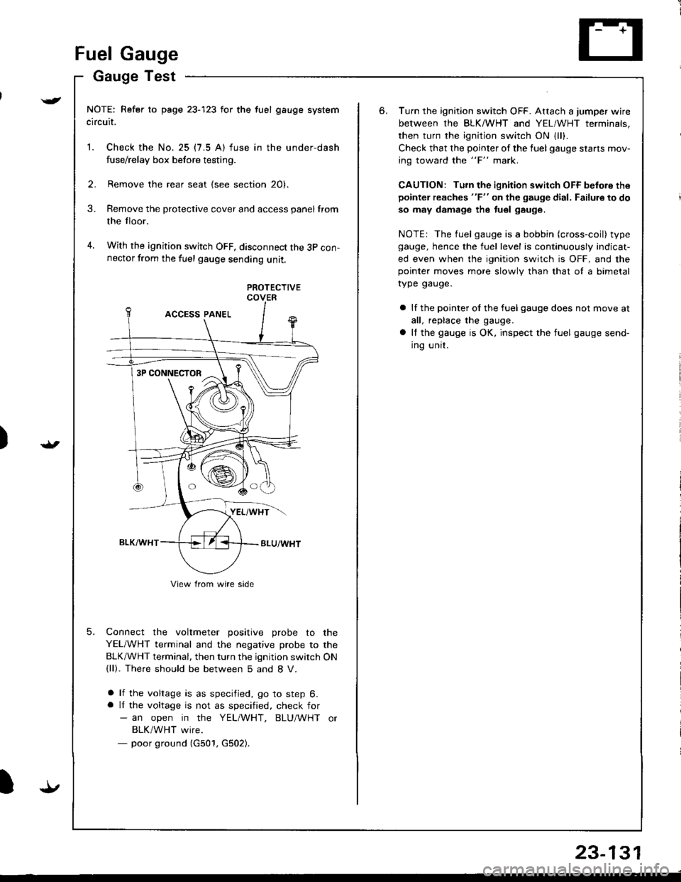
NOTE: Refer to page 23-123 for the fuel gauge system
circuit.
1. Check the No. 25 (7.5 A) fuse in the under-dash
fuse/relay box before testing.
2. Remove the rear seat (see section 20).
Remove the protective cover and access panel from
the tloor.
With the ignition switch OFF, disconnect the 3p con-nector from the fuel gauge sending unit.
3.
4.
5.
PROTECTIVECOVER
Connect the voltmeter positive probe to the
YEL/WHT terminal and the negative probe to the
BLK/WHT terminal, then turn the ignition switch ON(ll). The.e should be between 5 and 8 V.
a lf the voltage is as specified, go to step 6.a lI the voltage is not as specified, check for- an open in the YEL/WHT, BLU/WHT or
BLK/WHT wire.- poor ground (G501, G502).
3P CONNECTOR
View from wire side
6.Turn the ignition switch OFF. Attach a jumper wire
between the BLKMHT and YEL/WHT terminals,
then turn the ignition switch ON {1.,.
Check that the pointer of the fuel gauge starls mov-
ing toward the "F" mark.
CAUTION: Turn the ignition switch OFF before the
pointer reaches "F" on the gauge dial, Failure to do
so may damage the tuel gauge.
NOTE: The fuel gauge is a bobbin (cross-coil) type
gauge, hence the fuel level is continuously indicat-
ed even when the ignition switch is OFF, and thepointer moves more slowlv than that ol a bimetal
rype gauge.
a lf the pointer ol the fuel gauge does not move at
all, replace the gauge.
a It the gauge is OK, inspect the fuel gauge send-
ing unit.
Page 1283 of 1680
)
Function Test
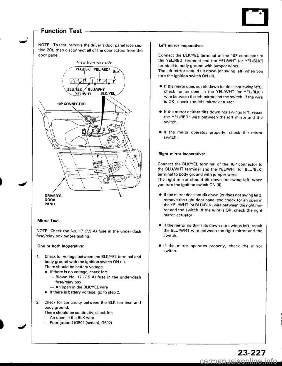
NOTE: To test, remove the driver's door panel (see sec-
tion 20), then disconnect all of the connectors from the
ooor panet.
Mifior Test
NOTE: Check the No. 17 {7.5 A) fuse in the under-dashfuse/relay box before testing.
One or both inoperative:
Check for voltage between the BLK//EL terminal and
body ground with the ignition switch ON {ll).There should be battery voltage.
. lf there is no voltage, check for:* Blown No. 17 (7.5 A) fuse in the under-dash
fuse/relay box- An open in the BLK/YEL wire
. lf there is battery voltage, go to step 2.
Check for continuity between the BLK terminal and
body ground.
There should be continuity; check for.* An open in the BLK wire- Poor ground (G501 (sedan), G502)
vrllBtxt YEL/RED' aa*\
Left miror inoperative:
Connect the BLK,^/EL terminal of the 1OP connector to
the YEVRED1terminal and the YEL /VHT (or YEL/BLK1)
terminal to body ground with iumper wires.
The left mirror should tilt down (or swing left) when you
turn the ignition switch ON (ll).
a lf the mirror does not tilt down (or does not swing lett).check for an open in the YEL/WHT {or YEL/BLKr}wire between the left mirror and the switch. lf the wireis OK, check the lett mirror actuaror.
a lf the mirror neither tilts down nor swings left, repair
the YEL/REDr wire between the letr mirror and theswtlcn.
a lf the mirror operates properly, check the mirror
swttcn.
Right mirrol inoperative:
Connect the BLK/YEL terminal of the 10P connector to
the BLU,^/VHT terminal and the YELMHT {or BLU/BLK)
terminal to body ground with jumper wires.
The right mirror should tilt down (or swing left) whenyou turn the ignition switch ON (ll).
a lf the mirror does not tilt down (or does not swing left),
remove the right door panel and check for an open in
the YEL/WHT (or BLU/BLK) wire between the right mir-
ror and the switch. lf the wire is OK, check the right
mirror actuator.
a lf the mirror neither tilts down nor swings lett, repair
the BLU/WHT wire between the right mirror and the
swrtch.
a lf the mirror operates properly, check the mirror
switch.
23-227
Page 1287 of 1680
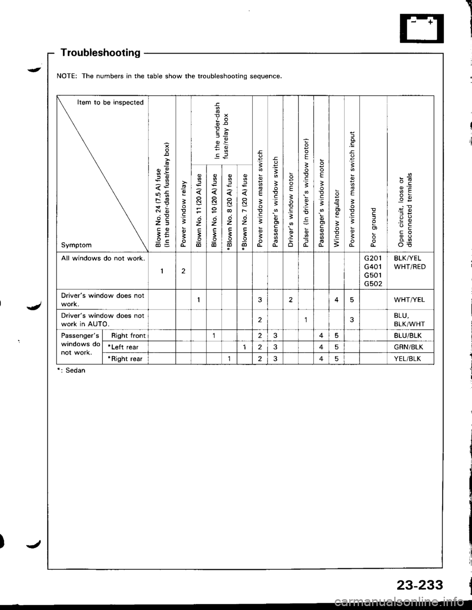
Troubleshooting
NOTE: The numbers in the table show the troubleshooting sequence
Item to be inspected
Symptom
;!
-!
z=
9cd)=
-9
3
;
oi
E
dr€
3
3
.=3
;
a
3
E.=3
E
;
;
.zo
E
3
.E3
!
o-
E
!.gi
oi
o-
og
3
c
.q
3
E
B
.gB
B
I
o)
c6z
3
6
N
z
;
6
z
'
6
N
F
z
B
@
All windows do not work.
12
G201
G401
G 501
G502
BLK/YEL
WHT/RED
Driver's window does not
work.25WHT/YEL
Driver's window does not
work in AUTO.23BLU,
BLK/WHT
Passenger's
windows do
not work.
Right front125BLU/BLK
*Left rear145GRN/BLK
*Right rear'lt?45YEL/BLK
*: Sedan
23-233
)t
Page 1289 of 1680
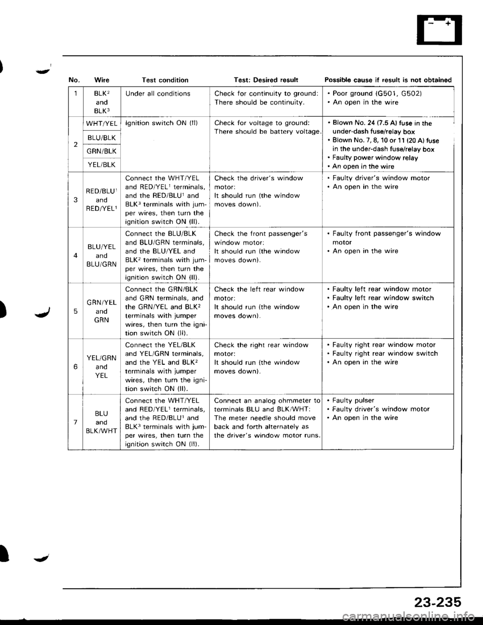
Test conditionPo$sible cause if result is not obtained
)
1BLK'
and
BLK3
Under all conditionsCheck for continuity to ground:
There should be continuity.
. Poor ground (G501, G502). An open in the wire
2
WHT/YELlgnition switch ON (ll)Check for voltage to ground:
There should be battery voltage
. Blown No. 24 (7.5 A) fuse in the
under-dash fuse/relay box. Blown No. 7, 8, 10 or 11 (20 Al fuse
in the under-dash fuse/relay box. Faulty power window relay' An open in the wire
B LU/BLK
G RN /BLK
YEL/BLK
3
RED/BLU I
and
R ED/YEL1
connect rhe wHT/YEL
and RED/YELr terminals,
and the RED/BLUland
BLK3 terminals with jum-
per wires, then turn the
ignition switch ON (ll).
Check the driver's window
motorl
It should run (the window
moves oown).
. Faulty driver's window motor. An open in the wire
BLU/YEL
and
BLU/GRN
Connect the BLU/BLK
and BLU/GRN terminals,
and the BLU/YEL and
BLK' terminals with jum-
per wires, then turn the
ignition switch ON (ll).
check the front passenger's
wtnoow molor:
It should run (the window
moves down).
. Faulty front passenger's window
motor. An open in the wire
5
G RN/YEL
ano
GRN
Connect the GRN/BLK
and GRN terminals, and
the GRN/YEL and BLK,
terminals with jumper
wires, then turn the igni
tion switch ON (ll).
Check the left rear window
motor:
It should run {the window
moves down|.
Faulty left rear window motor
Faulty left rear window switch
An open in the wire
6
YEL/GRN
and
YEL
Connect the YEL/BLK
and YEL/GRN terminals,
ANd thc YEL ANd BLK'
terminals with jumper
wires, then turn the igni-
tion switch ON (ll).
Check the right rear window
moror:
It should run lthe window
moves oownl.
Faulty right rear window motor
Faulty right rear window switch
An open in the wire
7
BLU
and
BLK/WHT
Connect the WHT/YEL
and RED/YELr terminals,
and the RED/BLUr and
BLK3 terminals with jum-
per wires, then turn the
ignition switch ON (ll).
Connect an analog ohmmeter to
terminals BLU and BLK/WHTI
The meter needle should move
back and fonh ahernalely as
the driver's window motor runs.
Faulty pulser
Faulty driver's window motor
An open in the wire
IJ
23-235
Page 1290 of 1680
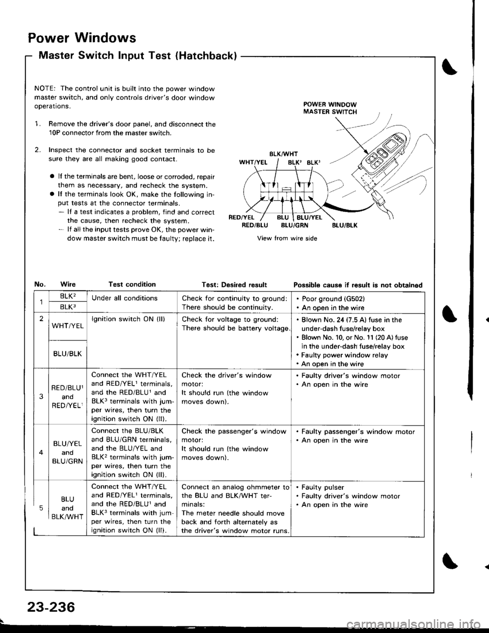
Power
Master
Windows
Switch Input Test (Hatchbackl
NOTE: The control unit is built into the power window
master switch, and only controls driver's door window
ooerations.POWER WINDOWMASTER SWITCH
1.Remove the driver's door panel, and disconnect the
10P connectorfrom the master switcn.
Inspect the connector and socket terminals to be
sure they are all making good contact.
a lI the terminals are bent, loose or corroded, reDair
them as necessary, and recheck the system.
a lf the terminals look OK, make the following in-
put tests at the connector terminals.- It a test indicates a problem, find and correct
the cause, then recheck the system.- lf all the input tests prove OK, the power win-
dow master switch must be taulty; reDlace it.
No.WileTest condition
BLK/WHT
BLK' BLKI
RED/YELRED/BLUBLU/GRNBLU/BLK
View from wire side
Tgst: DesiredresultPossibls cause if result is not obtainsd
BLU
and
BLK/WHT
Check for continuity to ground:
There should be continuity.
Poor ground (G502)
An open in the wire
lgnition switch ON (ll)Check for voltage to ground:
There should be battery voltage
. Blown No. 24 (7.5 A) fuse in the
under-dash fuse/relay box' Blown No. 10, or No. '11 (20 A) fuse
in the under-dash fuse/relay box. Faulty power window relay. An open in the wire
Connect the WHT/YEL
and RED/YELI terminals,
and the RED/BLU1 and
BLK3 terminals with jum-
per wires, then turn the
ignition switch ON (ll).
Check the driver's window
motor:
It should run (the window
moves oownl.
. Faulty driver's window motor. An open in the wire
Connect the BLU/BLK
and BLU/GRN terminals,
and the BLU/YEL and
BLK2 terminals wjth jum-
per wires, then turn the
ignition switch ON (ll).
Check the passenger's window
motor:
It should run (the window
moves oownl.
. Faulty passenger's window motor. An open jn the wire
Connect the WHT/YEL
and RED/YEL1 terminals.
and the RED/BLUI and
BLK3 terminals with jum-
per wires, then turn the
ignition swirch ON (ll).
Connect an analog ohmmeter to
the BLU and BLK/WHT ter-
minals:
The meter needle should move
back and forth alternately as
the driver's window motor runs.
. Faulty pulser. Faulty driver's window motor. An open in the wire
23-236
Page 1296 of 1680
![ACURA INTEGRA 1998 Service Repair Manual Power Door Locks
Circuit Diagram
@*"
DR]VERS000R LocKSWITCH
NATCN KEYCYLINDER SWITCH
L_____
ooon rocx xroe If7 l
VIKEY
DRIVERSDOOR LOCKACTUATOR
E
UNDER.HOOO FUSEi RELAY BOX
N0.41 (1004) No.s4 (40A)
ACURA INTEGRA 1998 Service Repair Manual Power Door Locks
Circuit Diagram
@*"
DR]VERS000R LocKSWITCH
NATCN KEYCYLINDER SWITCH
L_____
ooon rocx xroe If7 l
VIKEY
DRIVERSDOOR LOCKACTUATOR
E
UNDER.HOOO FUSEi RELAY BOX
N0.41 (1004) No.s4 (40A)](/manual-img/32/56983/w960_56983-1295.png)
Power Door Locks
Circuit Diagram
@*"
DR]VER'S000R LocKSWITCH
NATCN KEYCYLINDER SWITCH
L_____
ooon rocx xroe If7 l
VIKEY
DRIVER'SDOOR LOCKACTUATOR
E
UNDER.HOOO FUSEi RELAY BOX
N0.41 (1004) No.s4 (40A)
DFIVERS DOORKEY CYLJNOERSWITCH
WHT/GRN
FRONTPASSENGERSDOOR LOCKACTUATOR
T--=-l-4{il^
* LEFT REARDOOR LOCKACTUATOR
,@-
* RIGHT NEARDOOR LOCKACTUATOH
-4{.ill^
HATCH LOCKACTUATOR
T-:-lfl.|.{-
LTGRN
LT BLU
A
t--lt=JKEY
i
Atl
T-tl-lKEYBLK
I
G503
.LK BLKll
tlAA
:-l
G501 G2r.G502 ercl
BLK
,l'
G5o1G502
LOCK
o
POWER DOORLOCK CONTROLUNIT
8LK
A-l
G501G502
23-242