1998 ACURA INTEGRA Shift
[x] Cancel search: ShiftPage 35 of 1680

Lubrication Points
No. LUBRICAnON POINTSLUBRICANT
1 E^g,neAPI Service Grade: Use SJ "Energy Conserving" orSH "Energy Conserving ll" grade oil,The oil container may also display the API Certificationmark shown below. Make sure it savs "For GasolineEngines. "
SAE Viscositv: See chart below.
2TransmissionManualHonda Genuine MTF*1
AutomaticGenuine Honda Premium Formula AutomaticTransmission Fluid (ATF)*,
Brake line (lncludes Anti-lock brake line)Genuine Honda DOT3 Brake Fluid13
Clutch lineGenuine Honda DOT3 Brake Fluid*3
Power steering gearboxSteering grease P/N 08733 - 8070E
Release fork lManual transmission)Sup€r High Temp Urea Grease (P/N 08798 - 9002)
1
8
Throttle wire end (Dashboard lower oanel hole)Cruise control actuator wire end(Dashboard lower Danel hole)Silicone grease
o
10
11
14
Throttle cable end (Throttle link)Cruise control actuator cable end (Actuator link)Brake master cvlinder oushrodClutch master cylinder pushrod
Battery terminals
Fuel fill lid
Multi-purpose grease
to
17
18
Engin6 hood hinges and engine hood latchHatch hinges 8od latch or trunk hinges and latchDoor hjnges, upper and lowerDoor ooen detent
Honda White Lithium Grease
19Rear b.ake calipersSilicone grease
20Power steering systemGenuine Honda Power Steering Fluid-V or S*.
21Ai|' conditioning compressorRefrigerant oii ND-O|L8 {P/N38897 - PR7 - A01AH or38899-PR7-A01)(For Refrigerant: HFC-134a (R- 134a))
API SERVICE LABELAPI CERTIFICATION SEAL
Recommended engine oilEngin€ oil viscosity lorambrent lemperature ranges
r(For the details of lubrication points and type of lubricants to be applied, refer to the illustrated index and various work Dro-cedure (such as Assembly/Reassembly, Replacement, Overhaul, Installation. etc.) contained in each section,
*1: Always use Genuine Honda Manual Transmission Fluid (MTF). Using motor oil can cause stiffer shifting because itdoes not contain the proper addtuves.*2: Always use Genuine Honda Premium Formula Automatic Transmission Fluid (ATF). Using a non-Honda ATF can affectshift quality.*3: Always use Genuine Honda DOT 3 B.ake Fluid, Using a non-Honda brake fluid can cause corrosion and decrease thelife of the system.'4: Always use Genuine Honda Power Steering Fluid-V or S. Using any other type of power steering fluid or automatictransmission fluid can cause increase v,/ear and poor steering in cold weather.
L(
{
4-2
Page 50 of 1680

7
30.Disconnect the primary heated oxygen sensor(Primary HO2S) connector, then remove exhaust
pipe A.
818C1 engine:PRIMARYHO2S
8 x 1.25 mm24 N.m 12.4 kgl.m.t7 rbt.fttReplace.
GASKETReplace.
Replace.
SELF-LOCKING I{UT8 r 1.25 mm16 N.m (1 .6 kgf .m,
12 tbt.frtBeplace.
EXHAUSTPIPE A
NUT10 x 1.25 mm54 N.m {5.5 kgt'.n, tlo lbt.ft}Replace.
81881, 818C5 engines:
PRIMARYHO25 CONNECTOF
GASKETReplace.
GASKETReplace.
S€LF.LOCKING NUT
8 x 1.25 mm16 N.m (1.6 kgf'm,12 tbt.fr)Replace.f{UT10 x 1.25 mm54 N.m {5.5 kgf'm,40 lbf.ftlReplace.
8 x 1.25 mm24 N.m (2.4 kgt.m,17 lbf.frlReplace.
31. Remove the shift rod and extension rod {Mff).
8 x 1.25 mm22 N'm 12.2 kgl.m, '16 lbt.ttl
32. Remove the shift cable (A,/T).
I x 1.25 mm22 N-l'. 12.2 kgl.m,16 lbf.frl
SHIFT CABLE
CONTROLLEVER
6 x 'l.O mm14 N.m {1.4 kgf.m, 10 lbt.ft}
SHIFT ROD
RETAINER
SHIFT CABLE
LOCK WASHER
{cont'd)
COVER
5-9
Page 57 of 1680

Engine Removal/lnstallation
{cont'dl
7. Install the left front mount, then tighten the bolts in
the numbered sequence shown (O - @).
O t2 x '1.25 mm83 N.m 18.5 kgt.m,61 lbl.ft)Fleplace.
@ 12 x 1.25 mm59 N.m 16.0 kgf.m,43 lbf.frlReplace.
O 10 x 1.25 mmil4 N.m 14.5 kgt'm,33 lbt.ft)
,5-16
. Check that the spring clip on the end of each
driveshaft clicks into place.
CAUTION: Use new spring clips.
. Bleed air {rom the cooling system at the heater
valve open (see page 10-6).
. Adjust the throttle cable (see section 1 1).
. Check the clutch pedalfree play (see section 12).
. Check that the transmission shifts into gear
smoothlY.
. Adjust the tension of the following drive belts.
Alternator belt {see section 23).
P/S pump belt (see section 171.
A/C comDressor belt (see section 22).
! Inspect for tuel leakage (see section 1ll.. After assembling fuel line parts, turn on the
ignition switch (do not operate the staner) so
that the fuel pump operates for approximately
two seconds and the fuel line pressurizes.
Repeat this operation two or three times and
check for tuel leakage at any point in the {uel
line.
Page 244 of 1680

I
t
h,,l,!
il
Troubleshooting
ECM CONNECTOR {31P)
Engine Control Module Terminal Arrangement (cont'd)
ECM CONNECTOR C {31P)
235srsscs1112t31515t71A19
2A
Wire side of lemale terminals
NOTE: Standard battery voltage is 12 V.
TerminalnumbercolorTerminal namoD6scriptionSignal
1BLU/REDCKF P (CKF SENSOR P SIDE)Detects CKF sensor.With engine running: pulses
28LUCKP P (CKP SENSOR P SIDE)Detects CKP sensor.With engine running: pulses
3GRNTDC P {TDC SENSOR P SIDE)Detects TDC sensor,With engine running: pulses
YELCYP P (CYP SENSOR P SIDE)Detects CYP sensor,With engine running: pulses
5BLU/REDACS (AJC SWITCH SIGNAL)Detects A,/C switch signal.With A,/C switch ON: 0 VWith A,/C switch OFF: battery voltage
6BLUA/VHTSTS (STARTEB SWITCHSIGNAL)
Detects starter switch signal.With staner switch ON: battery voltageWith starter switch OFF: 0 V
7BRN,AiVHTSCS (SERVICE CHECKSIGNAL)Detects service check connectorsignal (the signalcausing a DTC;ndication).
With the co n nector con nected: 0 VWath the connector disconnected: about 5 V
8GRNAVHTK LINESends and receives OBD ll scantool and PGM tester signal.With ignition switch ON (ll): about 5 V
9YELFAS lFEEDBACK AT SIGNAL)Sends feedback signal for theTCM,At idle: about 5 VDuring shifting: momenlary change to 0 V
10WHT/BLU
VBU (VOLTAGE BACK UP)Power source for the ECMcontrolcircuit,Power source for the DTC
Battery voltage at all times
t1WHT/REDCKF M (CKF SENSOR I\4 SIDE)Ground for CKF sensor.
12BLUI/E LCKP M (CKP SENSOR M SIDE)Ground for CKP sensor.
WHT/BLUTDCM (TDC SENSOR M SIDE)Ground tor TDC sensor.
14CYPM (CYP SENSOR M SIDE)Ground for CYP sensor.
15*.BLU/BLKVTP SW (VTEC
PRESSUFE SWITCH)Detects VTEC pressure switchsr9nal.
With engine at low rpm:0 VWith engine at high rpmlbattery voltaqe
161,GRN
PSPSW (P/S OILPRESSURE SWITCH)Derecls PSP switch signal.At idle with steering wheel in straight aheadpositioni 0 VAt idle with steering wheelat full lock: batteryvoltage
17WHT/REDALTF (ALTERNATOR FRSIGNAL)Detects alternator FR signal.With fully warmed up engine running:0 V battery voltage (depending onelectrical load)
18ORNVSS (VEHICLE SPEEDSENSORiDetects VSS signal.With ignition switch ON (ll) and lrontwheels rotating: cycles 0 V- 5 V
19*3BLUAT CHK (A/T FI DATA LINE)Detects TCM data signal.With ignition switch ON (ll)i pulses
21*LT GRNBARO OUT (SAROMETRIC
SENSOR OUTPUT S!GNAL)Sends barometric sensor outputsrgnal,With ignition switch ON (ll): about 3 V(depending on barometric pressure)
27 x3GRYAFSB (A"/T FI SIGNAL B)Detects retard signal from theTCM,At idle: about 5 VDuring shifting: momentary changeto0V
28+1GRN/8LUA+SA (A/T FI SIGNAL A)Detects retard signal from theTCM.At idle: about 5 VDuring shifting: momentarV changeto0V
29+3LT GRN/BLKATPPN (A/T GEARPOSITION SWITCH)Detects A,/T gear position switchsrgnal-In E orE positionr 0VIn anv other position: battery voltage
*1: USA*2:818C1 engine*3: A/T*4: 818C1, 818C5 engines
Page 299 of 1680
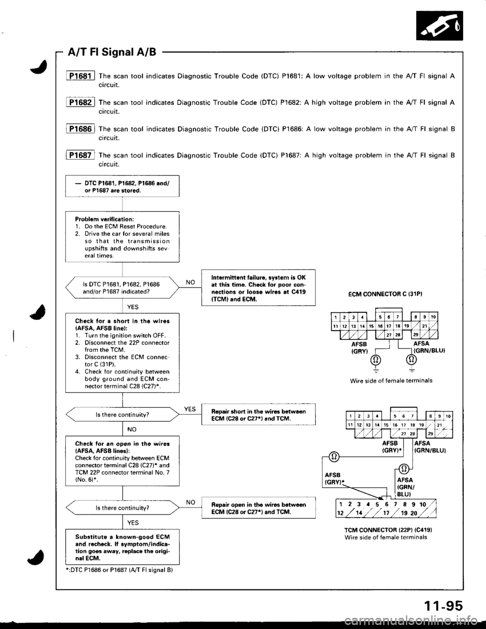
JP1681 | The scan tool indicates Diagnostic Trouble Code (DTC) P1681: A low voltage problem in the A/T Fl signal A
circuit.
P1682 | The scan tool indicates Diagnostic Trouble Code {DTC) Pl682: A high voltage problem in the A//T Fl signal A
circuit.
]TtOgOl fh" scan tool indicates Diagnostic Trouble Code (DTC) P1686: A low voltage problem in the A"/T Fl signal B
ctrcutt.
lFt Ogt-l fh" scan tool indicates Diagnostic Trouble Code (DTC) P1687: A high voltage problem in the A"/T Fl signal B
crrcurt.
ECM CONNECTOR C {31PI
IGRN/BLU)
Wire side of female terminals
TCM CONNECTOR {22P) {C419}Wire side of female terminals
2!a5't0
tl1213 tatat6It1a19 ,/
AFSB I I AFSA
{GRYI T- _IIGRN
@)o
2311to21 ;'15 15 17 13 13
E./ zl za
G-\
AFSIGR
\-
a
AFlGl
I
sBl
L]
r@!I AFSA
| {GRN/lRt ltl
iFSGRIA[/BLUt
12 3 a 5 6 7 89
tz /'tt //t't /ts zo
to ,/
DTC P1681, P1682, P1686 end/or P'1687 are stored.
Problem verificetion:1. Do the ECM Reset Procedure.2. orive the car for several milesso that the transmissionupshifts and downshifts severarlrmes.
Intormittent lailure. system is OKat thi3 tim€. Check tor ooo. con-nections or loo3o wir6s al C419{TCM} .nd ECM.
ls DTC P1681, P1682, Pl686and/or P1687 indicated?
Check tor a short in th6 wires{AFSA, AFSB linel:1. Turn the ignition switch OFF.2, Disconnect the 22P connectorfrom the TCM.3. Disconnect the ECM conn6c-tor C (31P).
4. Check for continuity betweenbody ground and ECM con-nector terminal C28 (C27)*.
Rcoair 3hort in tho wiros betweenECM lC28 or C27*l rnd TCM.ls there continuity?
Check fo. an open in the wiresIAFSA, AFSB lines):Check for continuity between ECMconnector terminal C28 (C27)* andTCM 22P connector terminal No. 7(No.6i*.
Repai. opsn in the wiros bdtweenECM lC28 or C27'l and TCM.
Subsiiiutg a known-good ECMend r6ch€ck. lf 3ymptom/indica-tion goes away, repl.c6 the origi-nal ECM.
":DTC P1686 or Pl687 (NT Fl sisnal 8l
1 1-95
Page 369 of 1680
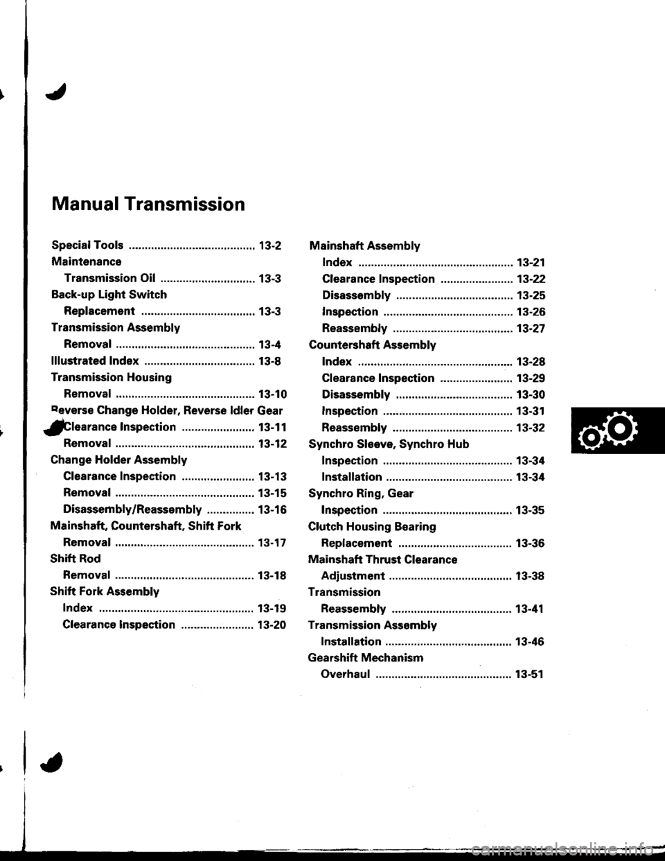
Manual Transmission
Special Tools ............. 13-2
Maintenance
Transmission Oil .............................. 13-3
Back-up Light Switch
Replacement ......... 13-3
Transmission Assembly
Removal ................. 13-4
lllustrated Index ................................... 13-8
Transmission Housing
Removal ................. 13-10
Peverse Change Holder, Reverse ldler Gear
jGlearance Inspection ....................... 13-1 1
Removal ................. 13-12
Change Holder Assembly
Clearance Inspection .....,.,....,,.....,,.. 13-13
Removal ................. 13-15
Disassembly/Reassembly ............... 13-16
Mainshaft, Countershaft, Shift Fork
Removal ................. 13-17
Shift Rod
Removal ................. 13-18
Shift Fork Assembly
Index ................ ...... 13-19
Clearance lnspection ...................,.,. 13-20
Mainshaft Assembly
fndex ................ ......13-21
Clearance f nspection ..,,,.................. 13-22
Disassembly .......... 13-25
Inspection .............. 13-26
Reassembly ........... 13-21
Countershaft Assembly
Index ................ ...... 13-28
Clearance Inspection ....................... 13-29
Disassembly .......... 13-30
Inspestion .............. 13-31
Reassembly ........... 13-32
Synchro Sleeve, Synchro Hub
Inspection .............. 13-34
Installation ............. 13-34
Synchro Ring, Gear
Inspection .............. 13-35
Clutch Housing Bearing
Replacement ......... 13-36
Mainshaft Thrust Clearance
Adiustment ............ 13-38
Transmission
Reassembly ........... 13-41
Transmission Assembly
Installation ............. 13-46
Gearshift Mechanism
Overhaul ................ 13-51
Page 371 of 1680

aintenance
Transmission Oil
NOTE: Check the transmission oil with the engine OFF
and the vehicle on level ground.
1. Remove the oil filler plug, then check the level and
condition of the oil.
OIL FILLER PLUG44 N.m {4.5 kgf.m,Proper Level33 tbf.ftl
The oil level must be up to the filler hole. lf it is
below the hole, add oil until it runs out, then rein-
stall the oil filler plug.
lf the transmission oil is dirty, remove the drainplug and drain the oil.
Reinstall the drain plug with a new washer, and
refillthe transmission oilto the proper tevet.
NOTE: The drain plug washer should be replaced at
every oil change.
Oil Capacity
2.2 | i.2.3 US.qr,1.9 lmp.qtl at oil ch.nge.
2.3 t l2.1US.qt,2.O lmp.qtl at ovorhaul.
Always use genuine Honda manual transmission
fluid (MTF). Using motor oil can causa€tiffer shift-
ing because it does not contain the proper addi-
Back-up Light Switch
Replacement
NOTE: To check the back-up light switch. see section 23.
1. Disconnect the connector, then remove the back-up
light switch connector from the connector clamp.
l.m {2.5 kgf.m, 18lbf.ft) Replace.
Remove the back-up light switch.
Install the new washer and the back-up light switch.
Check the transmission oil level.
!ves.
OIL FILLER PLUG
DRAIN PLUG39 N.m {4.0 kg{.m,29 rbf.ftlReplace.
5. Reinstall the oil filler plug with a new washer,
Replace.
EACK.UP LIGHT SWITCH25 N.m {2.5 kgf.m, 18 lbf.ft)
13.3
Page 374 of 1680

Transmission Assembly
Removal (cont'dl
14. Remove the driveshafts and the intermediate shaft
(see section 16).
NOTE: Coat all precision finished surfaces with
clean engine oil or grease. Tie plastic bags over the
driveshaft ends.
SET RINGBeplace.
DRIVESHAFTDRIVESHAFT Replace. trweinnro,ora ""ot
15. Remove the heat shield (Bl8c1 engine).
16. Remove the bolt, then disconnect the extension rod.
17. Remove the clip and the spring pin, then disconnect
the shift rod.
8x22mmSPRING PIN
CLIP Replace
fl noo
flil
\
I mm PINPUNCH
(818c1 .ngin.l
13-6
'18. Remove the front (Bl8C1 engine) and the rear
engine stiffeners,
REAR ENGINESTIFFENER
Remove the clutch cover {818C1 and 81881
enganes),
{B188l .ngin.}