Page 1048 of 1680
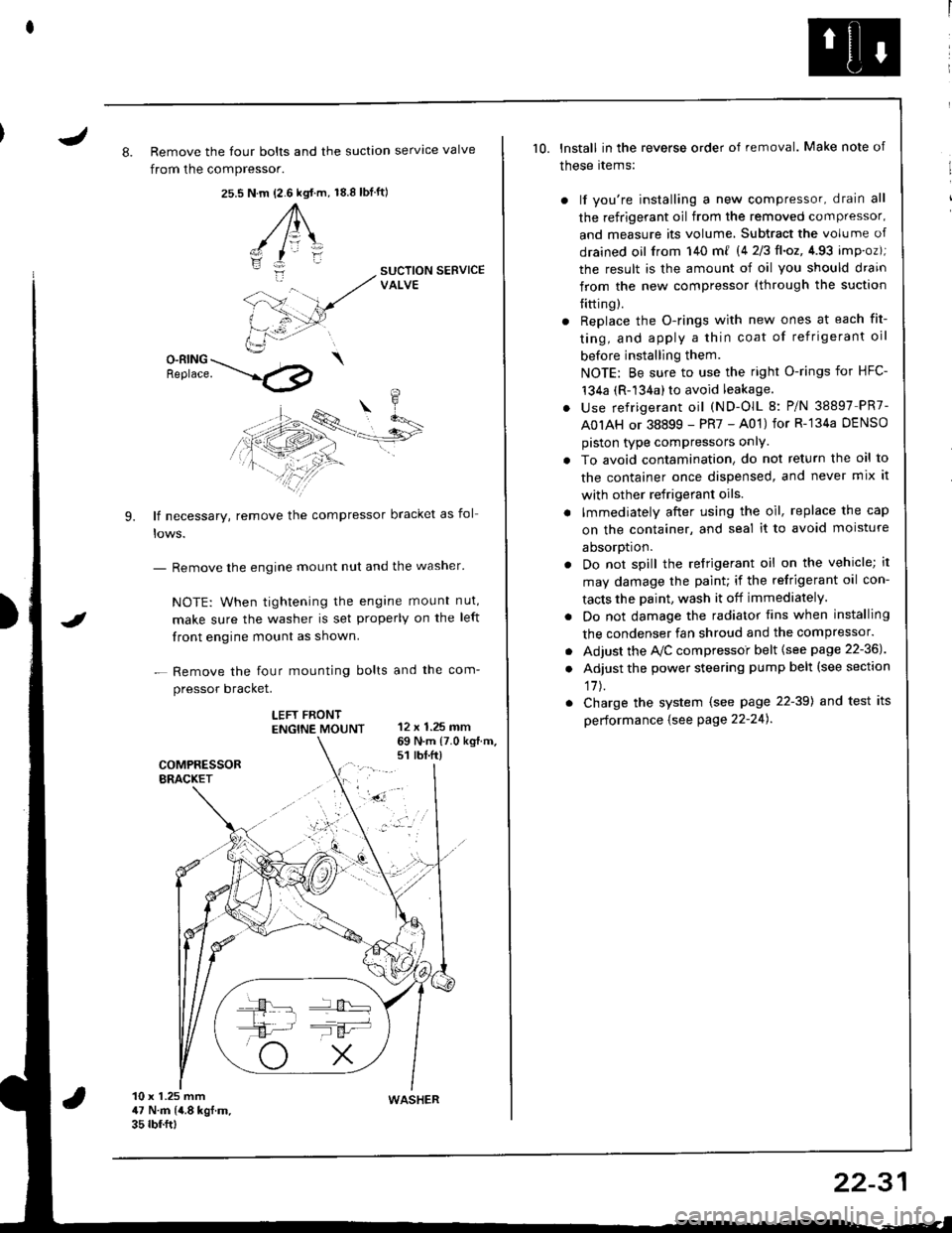
J8. Remove the four bolts and the suction servtce valve
from the compressor.
25.s18.8 tbf.ft)N.m {2.6 kgt.m,
A\
-/ l=\'zI
i:-
9.
SUCTION SERVICEVALVE
O-RING \Benrace. --'.l4p
lf necessary, remove the compressor bracket as fol
- Remove the engine mount nut and the washer'
NOTE: When tightening the engane mount nut,
make sure the washer is set properly on the left
front engine mount as shown.
- Remove the four mounting bolts and the com-
pressor bracket.
LEFT FRONTENGTNE MOUNT 12 x 1.25 mm
I
69 N.m {7.0 kg{.m.s1 rbt.ft)
10 x 1.25 mm47 N.m (4.8 kgf.m.35 rbf.ftt
10. lnstall in the reverse order of removal. Make note of
these rtems:
) lf you're installing a new compressor, drain all
the refrigerant oil from the removed compressor,
and measure its volume, Subtract the volume of
drained oil from 140 m{ 14 2/3ll.oz,4.93 imp.oz);
the result is the amount of oil you should drain
from the new compressor (through the suction
{itting).
r Replace the O-rings with new ones at each fit-
ting, and apply a thin coat of refrigerant oil
before installing them.
NOTE: Be sure to use the right O-rings for HFC-'t34a (R-134a) to avoid leakage.
. use refrigerant oil (ND-OlL 8: P/N 38897 PR7-
A0IAH or 38899 - PR7 - A01) for R-'134a DENSO
piston type compressors onlY.
. To avoid contamination, do not return the oil to
the container once dispensed, and never mix it
with other refrigerant oils.
. lmmediately after using the oil, replace the cap
on the container, and seal it to avoid moisture
aDsorDt|on.
. Do not spill the refrigerant oil on the vehicle; it
may damage the paint; if the refrigerant oil con-
tacts the Daint, wash it off immediately.
. Do not damage the radiator fins when installing
the condenser fan shroud and the compressor.
. Adjust the Ay'C compressoi belt {see page 22-36J
. Adjust the power steering pump belt (see section
17J.
. Charge the system (see page 22-39) and test its
performance {see Page 22-24).
WASHER
22-31
Page 1069 of 1680
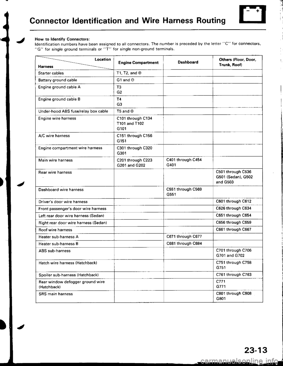
Connector ldentification and Wire Harness Routing
JHow to ldenti{v Connectors:
ldentification numbers have been assigned to all connectors. The number is preceded by the letter "C" for connectors,"G" for single ground terminals ot "f" lor single non-ground terminals.
/
Location
HarnossEngine CompartmentDashboardOthers (Floor, Door,
Trunk. Rooll
Starter cablesT1, T2, and @
Battery ground cableG1 and O
Engine ground cable A
G2
Engine ground cable BT4
G3
Under-hood ABS fuse/relav box cableT5 and @
Engine wire harnessC101 through C134
T101 and T102
G101
A,/C wire harnessC151 through C156
G151
Engine compartment wire harnessC301 through C320
G301
Main wire harnessC201 through C223
G20'l and G202
C40l through C454
G401
Rear wire harnessC501 through C536
G501 (Sedan), G502
and G503
Dashboard wire harnessC551 through C569
G551
Driver's door wire harnessC601 through C612
Front passenger's door wire harnessC626 through C634
Left rear door wire harness (Sedan)C65l through C654
Right rear door wire harness (SedanlC656 throughc659
Roof wire harnessC661 through C667
Heater sub-harness AC671 through C677
Heater sub-harness BC68l through C684
ABS sub-harnessC701 through C706
G701 and G702
Hatch wire harness (Hatchback)C751 through C758
Spoiler sub-harness {Hatchback)C761 through C763
Rear window defogger ground wire
(Hatchback)
c11 l
G77'l
SRS main harnessC801 through C808
G801
23-13
Page 1072 of 1680
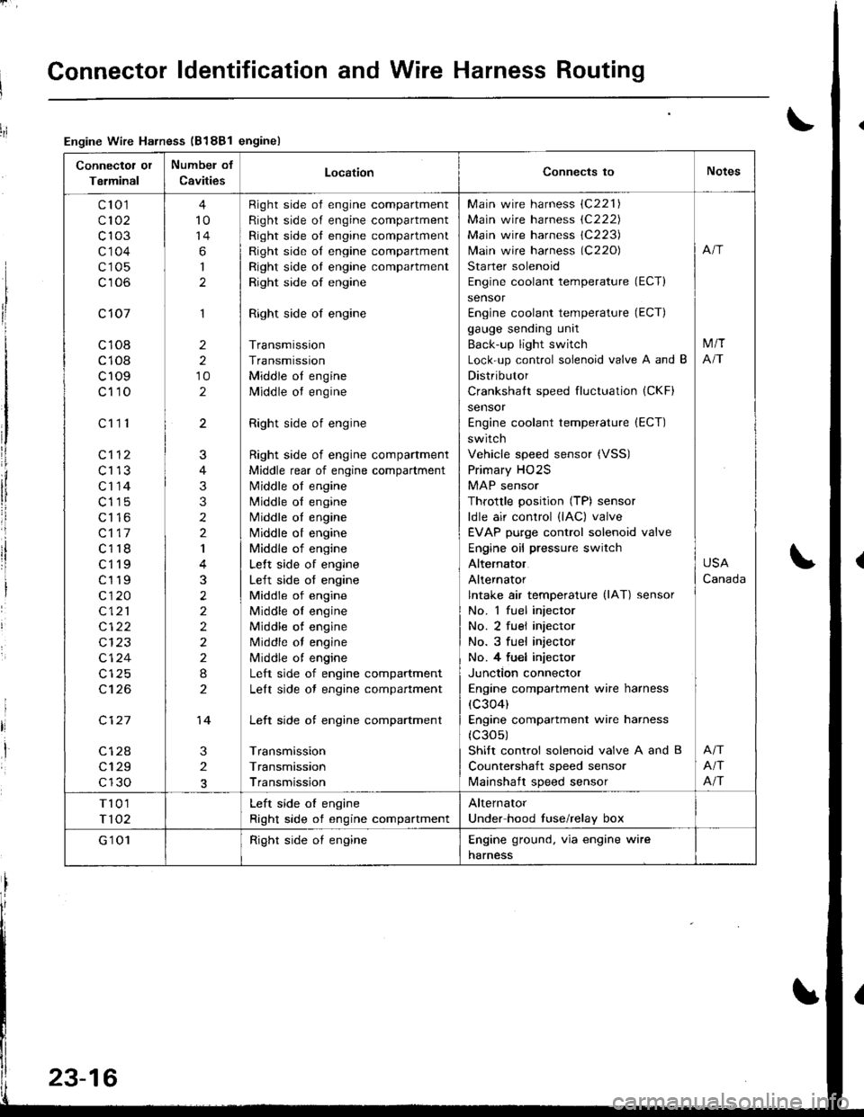
Connector ldentification and Wire Harness Routing
Connectot or
Terminal
Numbel of
CavitiesLocationConnects toNotes
c'to 1
c102
c103
c'1 04
c105
c106
c 107
c108
c108
c109
c110
c112
c113
c'r 14
c115
c116
c117
c118
ct'l9
c119
c120
c121
c122
c124
c't 26
c127
c128
c129
c130
c111
4
10
14
6
I
1
2
2
10
2
3
2
J
4
3
3
2
2
I
3
2
2
2
2
2
I
2
14
Right side of engine compartment
Right side of engine compartment
Right side ot engine compartment
Right side of engine compartment
Right side oI engine compartment
Right side of engine
Right side of engine
Transmission
Transmission
Middle ot engine
Middle ot engine
Right side of engine
Right side of engine compartment
Middle rear of engine compartment
N4iddle of engine
N4iddle ol engine
Middle oI engine
Nliddle ot engine
Middle of engine
Lelt side of engine
Left side of engine
Middle of engine
Middle oI engine
Middle of engine
Middle of engine
Middle ot engine
Left side of engine compartment
Lelt side ot engine compartment
Left side of engine compartment
Transmission
Transmission
Transmission
Main wire harness (C221)
Main wire harness (C222)
Main wire harness 1C223)
lvlain wire harness (C220)
Starter solenoid
Engine coolant temperature (ECT)
sensor
Engine coolant temperature (ECT)
gauge sending unit
Back-up light switch
Lock-up control solenoid valve A and B
Distributor
Crankshatt speed fluctuation (CKF)
sensor
Engine coolant temperature (ECT)
switch
Vehicle speed sensor (VSS)
Primary HO2S
MAP sensor
Throttle position (TP) sensor
ldle air control (lAC) valve
EVAP purge control solenoid valve
Engine oil pressure switch
Alternator
Alternator
lntake air temperature (lAT) sensor
No. 1 fuel injector
No. 2 fuel injector
No. 3 fuel injector
No. 4 fu€l injector
Junction connector
Engine compartment wire harness
(c304)
Engine compartment wire harness
(c30s)
Shift control solenoid valve A and B
Countershaft speed sensor
lvlainshaft speed sensor
M/T
NT
USA
Canada
Afi
Afi
T101
T102
Left side oI engine
Right side of engine compartment
Alternator
Under hood fuse/relay box
G'1 01Right side oI engineEngine ground. via engine wire
harness
Engine Wire Harness (B188l enginel
23-16
Page 1074 of 1680
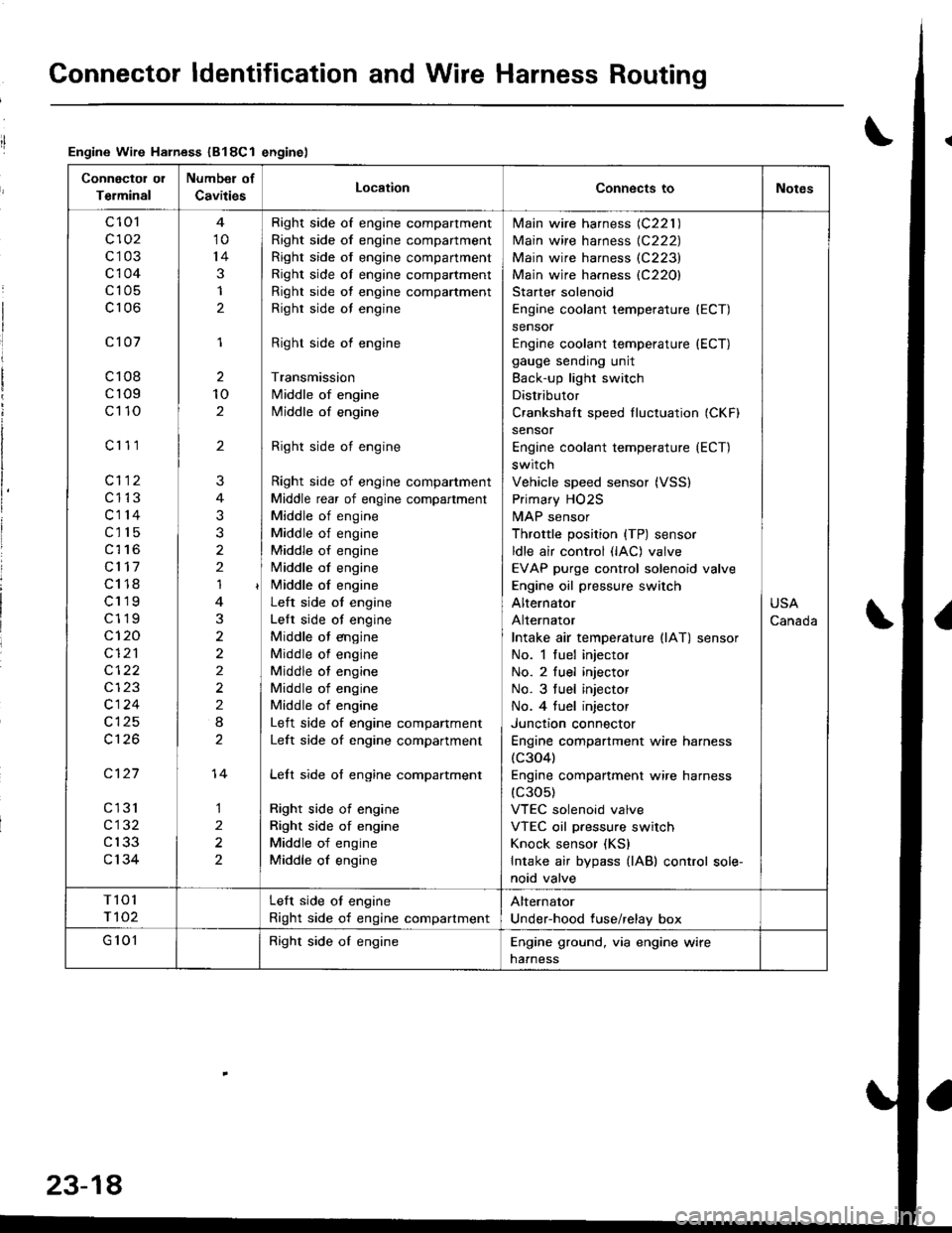
Connector ldentification and Wire Harness Routing
Engine Wire Harness (B18Cl enginel
Connectol ol
Terminal
Number of
CavitiesLocationConnects toNotes
c 101
c102
c103
c104
c105
c106
c101
c108
cr09
c110
c'r 11
cl12
c1't3
c114
c115
c116
cl17
c118
c119
c119
c120
cI2'l
cl24
c126
c127
cl31
c132
c133
c134
10
14
3
1
2
1
2
10
2
'I
3
2
2
2
I
1
2
2
?
3
2
14
Right side of engine compartment
Right side of engine compartment
Right side of engine compartment
Right side ol engine compartment
Right side of engine compartment
Righr side oI engine
Right side of engine
Transmission
Middle of engine
Middle of engine
Right side of engine
Right side of engine compartment
Middle rear of engine compartment
Middle of engine
Middle of engine
Middle of engine
Middle of engine
i/iddle of engine
Left side ot engine
Lelt side ot engine
Middle ot engine
Middle of engine
Middle of engine
Middle of engine
Middle of engine
Left side of engine companment
Left side of engine compartment
Lelt side of engine compartment
Right side of engine
Right side of engine
Middle of engine
Middle of engine
lvlain wire harness (C221 )
Main wire harness {C222)
Main wire harness (C223)
Main wire harness (C220)
Starter solenoid
Engine coolant temperature (ECT)
sensor
Engine coolant temperature (ECT)
gauge sending unit
Back-up light switch
Distributor
Crankshalt speed fluctuation (CKFI
sensor
Engine coolant temperature {ECT)
switch
Vehicle speed sensor (VSS)
Primary HO2S
MAP sensor
Throttle position {TP) sensor
ldle air control (lAC) valve
EVAP purge control solenoid valve
Engine oil pressure switch
Alternator
Alternator
Intake air temperature llAT) sensor
No. 1 fuel injector
No. 2 fuel injector
No. 3 tuel injector
No. 4 tuel injector
Junctron connector
Engine compartment wire harness(c304)
Engine companment wire harness(c30s)
VTEC solenoid valve
VTEC oil pressure switch
Knock sensor (KS)
Intake air bypass {lAB) control sole-
noid valve
USA
Canada
T101
r 102
Left side ot engine
Right side of engine compartment
Alternator
Under-hood fuse/relay box
G 101Right side of engineEngine ground, via engine wire
naaness
23-18
Page 1154 of 1680
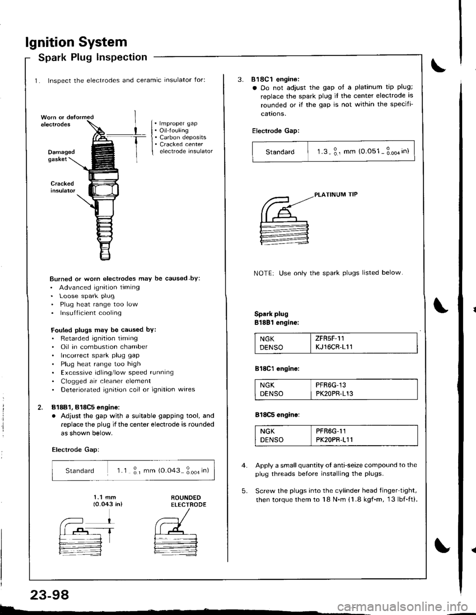
lgnition System
1. Inspect the electrodes and ceramic insulator for:
Spark Plug lnspection
. lmproper gap. Oil-fouling. Carbon deposits. Cracked centerelectrode insulatorDamagedgaskei
Burned or worn electrodes may be caused by:
. Advanced ignition timing. Loose spark plug
. Plug heat range too low. Insufficient cooling
Fouled plugs may be caused bY:. Retarded ignition liming. Oil in combustion chamber. Incorrect spark plug gap
. Plug heat range too high. Excessive rdling'low speed running
. Clogged air cleaner element. Deteriorated ignition coil or ignition wires
81881, 818C5 engine:
. Adjust the gap wjth a suitable gapping tool, and
replace the plug if the center electrode is rounded
as shown below.
Electrode Gap:
Standard 'l .1 ; r mm {0.043 ; ooa in)
E.
23-98
3.818C1 engine:
a Do not adjust the gap ol a platinum tip plug;
replace the spark plug it the center electrode is
rounded or if the gap is not within the specifi-
cattons.
Electrode Gap:
Standard I t.s-3., mm (0.051-3.oo4in)
5.
PLATINUM TIP
NOTE: Use onlv the spark plugs listed below
Spark plug
Bl88l engine:
NGK I ZFR5F-11
DENSO I KJ 16CR-111
818C1 engine:
NGK PFR6G-13
DENSO I PK2OPR-113
818C5 engine:
NGK PFR6G-I1
DENSO PK2OPR-111
Apply a small quantity ot anti-seize compound to the
plug threads belore installing the plugs.
Screw the plugs into the cylinder head tinger tight,
then torque them to 18 N.m (1 .8 kgf.m, 13lbf.ft).
Page 1176 of 1680
Gauge Assembly
Component Location Index
VEHICLE SPEED SENSOR {VSSITest, page 23-128Input Test, page 23-128Replacement, page 23-130
GAUGE ASSEMBLYGauge Location Index, page 23-12:|fndicator Location Index. page 23-121Terminal Location Index, page 23-121Eulb Location, pag6 23-122Disassembly, page 23-127Removal, paqe 23-126
FUEL GAUGE SENDING UNITTest, page 23-132Replacement, page 23-132
PARKING BRAKE SWNCHTest, page 23-135
ARAKE FLUID LEVEL SWITCHTest, page 23,135
ENGINE OIL PRESSURE SWITCHTest, p6ge 23-130
ENGINE COOLANT TEMPERATUFE IECTI GAUGESENOING UNITTest, page 23-134
23-120
Page 1178 of 1680
I
rIGauge Assembly
BulbLocations
RIGHT TURN SIGNAL INOICATOR LIGHT ('I.4 WI
BRAKE SYSTEM LIGHT I1.4 WI
DOOR-OPEN INDICATOR LIGHT (1.4 WI
*ABS/SRS INOICATOR LIGHT (1.' W)
LOW FUEL INDICATOR I-IGHT I3.4 W)
SEAT BELT REMINDER LIGHT {1.4 WI
HATCH-OPEN INDICATOR LIGHT {1.4 W}: HarchbackTRUNK'OPEN INDICATOR LIcHT (1.4 W): Sedan
+: On the ABS/SRS printed circuit board
LEFT TURN SIGNAL INDICATOR LIGHT (1.4 WI
CHARGING SYSTEM LIGHT {1,4 WI
A/T GEAR POSITION INDICATOR LIGHT (1.'t2 W x 7)
HIGH BEAM INDICATOR LIGHT I1 .4 \A,
LOW ENGINE OIL PRESSUREINDICATOR LIGHT (1.4 W}
MALFUNCTION INDICATOR LAMP(MtLl (1.4 Wl
LIGHTS13.4 W x 3)REMINDER LIGHT I1.4 WI
cRursE LTGHT | 1.4 Wt
23-122
Page 1181 of 1680
J
BLKYEL
YEUBLU
A8SN0.53 (104) FUSE CONTROLlFrofi page 23A'123) UNIT
VV
II
tltlWHT/GFN BLU/REO
lonWHT€IU
I
I
I
\?
ALTERNATOR
lo'PNK
J
HAZAROWARNINGswtTcH
MENTENANCEREMINDERLIGHT0.4v,/i
lo'PNK
II
I
J
MAINTENANCEREMINDERUNIT
| 011
YEUREO
I
T
P"-:
)-
BLK
I:
G201G401
LOWENGINE OILPFESSUREINDICATORLIGHT0.4w)
23-125
)J