Page 1290 of 1680
Power
Master
Windows
Switch Input Test (Hatchbackl
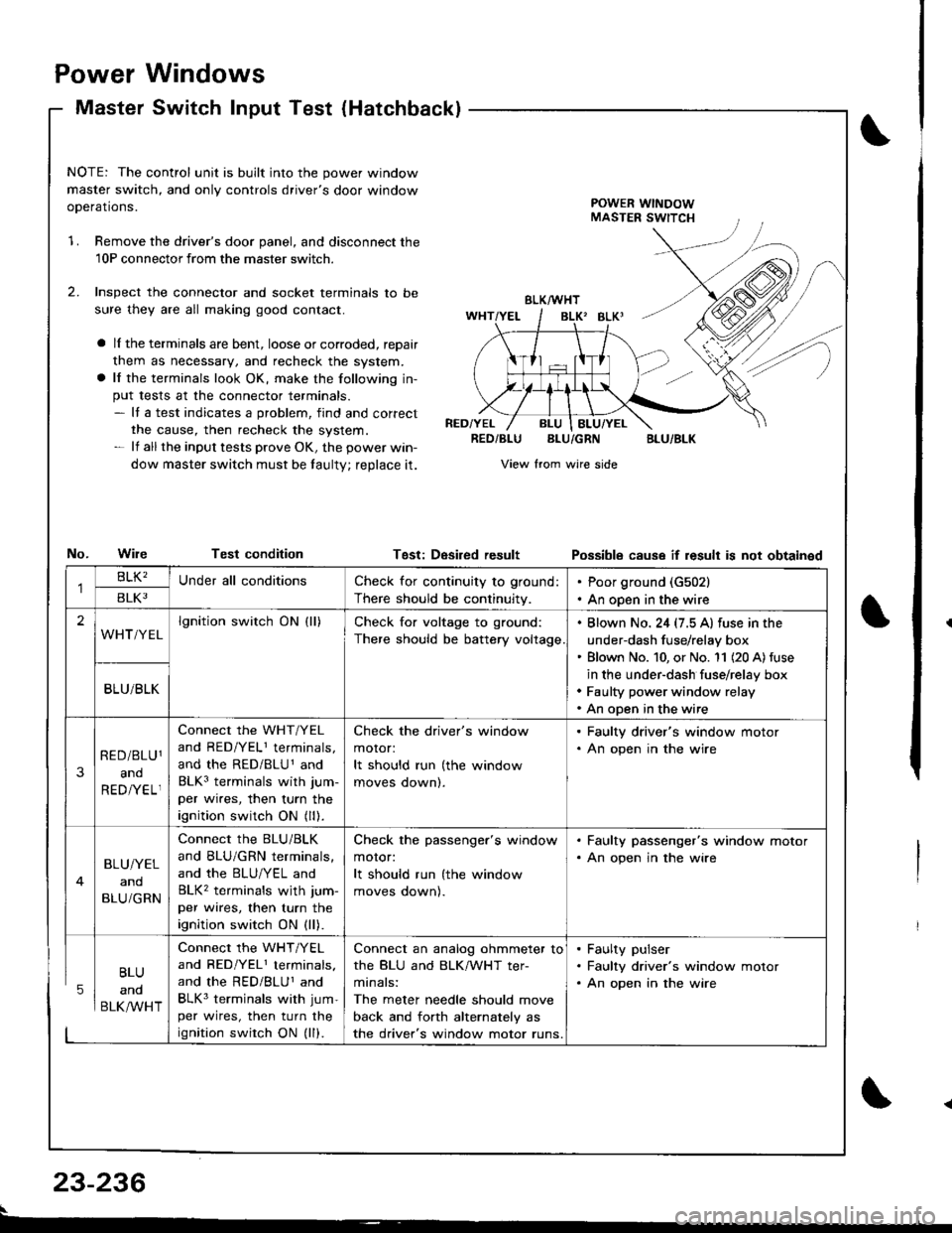
NOTE: The control unit is built into the power window
master switch, and only controls driver's door window
ooerations.POWER WINDOWMASTER SWITCH
1.Remove the driver's door panel, and disconnect the
10P connectorfrom the master switcn.
Inspect the connector and socket terminals to be
sure they are all making good contact.
a lI the terminals are bent, loose or corroded, reDair
them as necessary, and recheck the system.
a lf the terminals look OK, make the following in-
put tests at the connector terminals.- It a test indicates a problem, find and correct
the cause, then recheck the system.- lf all the input tests prove OK, the power win-
dow master switch must be taulty; reDlace it.
No.WileTest condition
BLK/WHT
BLK' BLKI
RED/YELRED/BLUBLU/GRNBLU/BLK
View from wire side
Tgst: DesiredresultPossibls cause if result is not obtainsd
BLU
and
BLK/WHT
Check for continuity to ground:
There should be continuity.
Poor ground (G502)
An open in the wire
lgnition switch ON (ll)Check for voltage to ground:
There should be battery voltage
. Blown No. 24 (7.5 A) fuse in the
under-dash fuse/relay box' Blown No. 10, or No. '11 (20 A) fuse
in the under-dash fuse/relay box. Faulty power window relay. An open in the wire
Connect the WHT/YEL
and RED/YELI terminals,
and the RED/BLU1 and
BLK3 terminals with jum-
per wires, then turn the
ignition switch ON (ll).
Check the driver's window
motor:
It should run (the window
moves oownl.
. Faulty driver's window motor. An open in the wire
Connect the BLU/BLK
and BLU/GRN terminals,
and the BLU/YEL and
BLK2 terminals wjth jum-
per wires, then turn the
ignition switch ON (ll).
Check the passenger's window
motor:
It should run (the window
moves oownl.
. Faulty passenger's window motor. An open jn the wire
Connect the WHT/YEL
and RED/YEL1 terminals.
and the RED/BLUI and
BLK3 terminals with jum-
per wires, then turn the
ignition swirch ON (ll).
Connect an analog ohmmeter to
the BLU and BLK/WHT ter-
minals:
The meter needle should move
back and forth alternately as
the driver's window motor runs.
. Faulty pulser. Faulty driver's window motor. An open in the wire
23-236
Page 1291 of 1680
Master Switch Test (Sedanl
't
J)
I
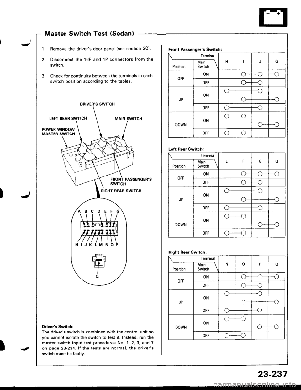
1.Remove the driver's door panel (see section 20).
Disconnect the 16P and 1P connectors from the
switch.
Check Jor continuity between the terminals in each
switch position according to the tables.
,,
s swtTcH
LEFT REAF SWITCHMAIN SWITCH
POWER WINDOWMASTER SWITCH
PASSENGER'SswtTcH
RIGHT REAR SWITCH
Drivsr's Switch:
The driver's switch is combined with the control unit so
vou cannot isolate the switch to test it. Instead, run the
master switch input test procedures No. 1, 2, 3. and 7
on page 23-234. lf the tests are normal, the driver's
switch must be faulty.
Front Passenger's Swltch:
Terminal
JoI uain \Position I Switch \
OFFONG_o--o
OFFG*--o
UPONo---o
o-
OFFo---o
DOWNONo---o
G-_O
OFFG--o
ABCDEFG
HIJKLMNO
L€ft Rear Switch:
Terminal
EFGoI Main \Position I Switch \
OFFONo-o--o
OFFo---o
UPONo---o
--oo-
OFFo---o
DOWNONo---o
o--o
OFFo--o
Right Rear Switch:
Terminal
ooPosirion | 35ii.r \
OFFONG-
OFFo-._,f
UPON.)-]--------{-)1___i----o
OFFo--o
DOWNONc-l
o-
oFF :----o
J
23-237
Page 1292 of 1680
Power Windows
Master Switch Test (Hatchback)Passenger's Window Switch Test
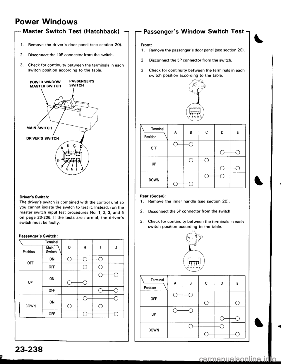
Remove the driver's door panel (see section 20).
Disconnect the 10P connector trom the switch.
Check for continuity between the terminals in each
switch position according to the table.
POWERwtNDOW PASSENGER'S
MASTER SWTTCH swtTCH
Driver's Switch:
The driver's switch is combined with the control unit so
you cannot isolate the switch to test it. Instead, run the
master switch input test p.ocedures No. 1, 2, 3, and 5
on page 23-236. lf the tests are normal, the driver's
switch must be iaultv.
/+ r' \'ir=i;l,r
.JJ#iill
ryfi'\
Front:'1. Remove the passenger's door panel (see sectaon 20).
2. Disconnect the 5P connector from the switch.
3. Check for continuity between the terminals in each
switch position according to the table.
Real (Sedan):
1. Remove the inner handle (see section 20).
2. Disconnect the 5P connector from the switch.
3. Check tor continuity between the terminals in each
switch position according to the table.
Terminal
'*';__\cD
OFFo---o
o---o
UPo---o
o-
DOWN
o---o
o--'o
Terminal
t"t-* \cD
OFFo---o
o---o
UPo--_o
o---o
DOWNo---o
--oo-
Passenger's Switch:
23-238
Page 1293 of 1680
Hatchback:
1. Remove the driver's door panel (see section 20).
2. Disconnecl the 10P connector from the switch.
3. Remove the three mounting screws and the switch.
Sedan:
1. Remove the driver's door panel (see section 20).
2. Disconnect the 16P and 1P connectors from the
swrtcn.
3. Remove the two mounting screws and the switch.
POWER MIRRORswtrcH
scBEws
Master Switch ReplacementPassenger's Window Switch
I-
.J)
I
Replacement
Front:
1 . Remove the passenger's door panel lsee section 20).
2. Disconnect the 5P connector from the switch.
3. Remove the two mounting screws and the switch.
Rear (Sedan);
1. Remove the inner handle (see section 2O).
2. Disconnect the 5P connector from the switch.
3. Remove the two mounting screws and the switch.
wtNDowswrTcH
swtTcH
5P CONNECTOR
IN ER HATOLE
23-239
Page 1294 of 1680
Power Windows
Driver's Window Motor Test
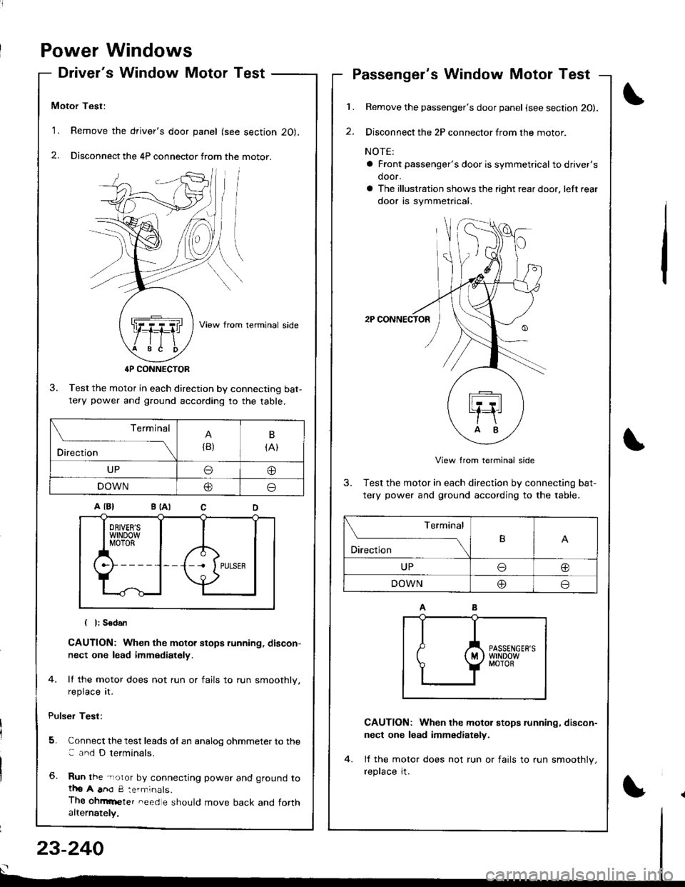
Motor Test:
'1. Remove the driver's door panel (see section 20).
2. Disconnect the 4P connector from the motor.
View from terminal side
4P CONNECTOR
3. Test the motor in each direction by connecting bat-tery power and g.ound according to the table.
CAUTION: When the motor stops running, discon-
nect one lead immediately.
4. lf the motor does not run or fails to run smoothly.
reprace rI.
Pulser Test:
5. Connect the test leads of an analog ohmmeter to the: and D terminals.
6. Run the -noror by connecting power and ground totho A anO 8:errninals.
Thg ohmrneter need e should move back and forthalternately,
1.
2.
Passenger's Window Motor Test
Remove the passenger's door panel {see section 20).
Disconnect the 2P connector from the motor.
NOTE:
a Front passenger's door is symmetricalto driver's
door.
a The illustration shows the right rear door. left rear
door is symmetrical.
2P CONNECTOR
View from terminal side
3. Test the motor in each direction by connecting bat-
tery power and ground according to the table.
CAUTION: When the motol stops running, discon-
nect one lead immediately.
lf the motor does not run or fails to run smoothlv,
reprace rI.
(
I
Terminal
Direction{B)
B
{At
UPo@
DOWN@o
Terminal
O'*"r*-TB
UPo@
DOWN@o
23-240
Page 1327 of 1680
Rear Window Wiper Motor Test
J
J
1 . Disconnect the 4P connector from the wiper motor.3. lf the motor does not run or fails to run smoothly,
replace it.
4. Reconnect the 4P connector to the wiper motor
assemDty.
5. Connect an analog voltmeter between the D (LT
GRN/BLK) and B (BLKI terminals. Run the motor by
turning the wiper switch ON.
The voltmeler should alternately indicate O V and
more than 4 V.
NOTE: Use an analog tester.
1PCONNECTOR
A (GRN/BLKI
C IGRN)
View from terminal side
2. Test the motor by connecting battery power to the
A {GRN/BLK) and ground to the C (GRN) terminals.
The motor should run smoothly.
C IGRN}
);
23-273
Page 1328 of 1680
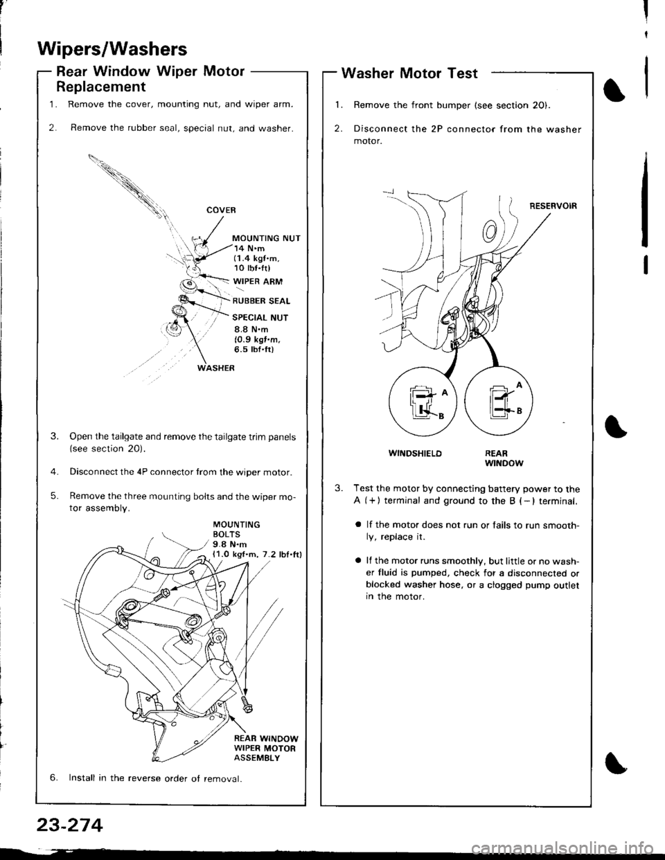
1.
2.
Replacement
Remove the cover, mounting nut, and wiper arm.
Remove the rubber seal, special nut, and washer.
COVEB
MOUNTING NUT
WASHER
14 N'm(1.4 kgt.m,10 tbf.tr)
WIPER ARM
RUBBER SEAL
SPECIAL NUT
8.8 N.m
10.9 kgf.m.6.5 tbf'fr)
MOUNTINGBOLTS9.8 N.m11.0 kgl.m, 7.2 lbl.lrl
REAR WINOOWWIPER MOTORASSEMELY
3.Open the tailgate and remove the tailgate trim panels
{see section 20).
Disconnect the 4P connector trom the wiper motor.
Remove the three mounting bolts and the wiper mo-
tor assembly.
5.
6. Install in the reverse order ot removal.
,'II
t
Wipers/Washers
Rear Window Wiper MotorWasher Motor Test
l�
2.
Remove the front bumper (see section 20).
Disconnect the 2P connector from the washer
motor.
RESERVOIR
1
WINDSHIELDREARwtNDow
3.Test the motor by connecting battery power to the
A (+) terminal and ground to the B (-lterminal.
a lf the motor does not run or fails to run smooth-
ly, replace it.
a lf the motor runs smoothly, but little or no wash-
er fluid is pumped, check for a disconnected orblocked washer hose, or a clogged pump outletIn the motor.
23-274
Page 1382 of 1680
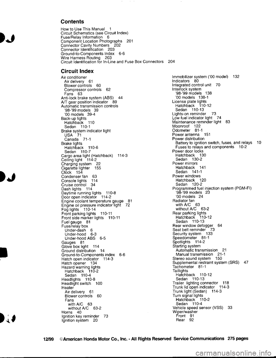
).1
Contents
How to Use This l\.4anual 1Circuit Schematics (see Circuit Index)Fuse/Relaylnformation 6ComponentLocation Photographs 201
Connector Cavity Numbers 202Connectorldentification 203
Ground-to-Components Index 6-6Wire Harness Routing 203Circuit ldentification lor ln-Line and Fuse Box Connectors
Circuit Index
Air conditionerAir delivery 61Blower controls 60Compressor controls 62Fans 63Anti-lock brake system (ABS) 44A/T gear position indicator 89Automatic transmission controls'98199 models 39'00 models 39-4Back-up lightsHatchback 110Sedan 110- 1Brake system indicator light
USA 71Canada 71-1Brake lightsHatchback 110-6Sedan 110-7Cargo area light (Hatchback) 114-3Ceiling light 114-2Charging system 22Cigarette lighter 155
Clock 154Condenser fan 63Console lights 114Cruise control 34Dash lights 1 14Daytime running lights 110-8Door open indicator 114-2Engine coolant temperature gauge 81Engine oil pressure indicator light 72Fog lights 110-14Front parking lights 110-11Front side marker lights 110-11Fuel gauge 81Fuse/relay boxUnder-dash 6Under-hood 6-3Under-hood ABS 6-5Gauges 81Glove box light 114Ground distribution 14Ground-to-Componentsindex 6-6Hatch open indicator '114-3
Hatch opener '134
Hazard warning lightsHatchback 'l l0-2Sedan 110-4Headlights 1'10-8Headlight switch 100HeaterAir delivery 61Blower controls 60Fanswith A,/C 63without A,/C 63-2Horns 40lgnilion key reminder 73lgnition system 20
204
lmmobilizer system ('00 model) 132lndicators 80Integrated control unit 70Interlock system'98199 models 138'00 models 138-1License plate lightsHatchback 110-12Sedan 110-13Lights-on reminder 73Low fuel indicator light 74l\,4aintenance reminder light 83l\iloonroof 122Odometer 81-1Power antenna 151Power distributionBattery to ignilion switch, fuses, and relays
Fuses to relays and components 10-2Power door locksHatchback '130
Sedan 130-2Power mirrorsHatchback 141Sedan 141-1Power windowsHatchback 120Sedan 120-2Programmed fuel injection system (PGM-Fl)'98199 models 23'00 models 24Radiator fanwith tuC 63without A,/C 63-2Rear parking lightsHatchback 110-12Sedan 110- 13Rear window defogger 64Seat belt reminder 73Security system 133Speedometer Il-1Spotlights 114-2Starting syslemAutomalictransmission 21l\.4anualtransmission 21-1Stereo sound system 150Supplemental restraint system (SRS) 47Tachometer 81- 1TaillightsHatchback 110-12Sedan 110-13Trailer lighting conneclor 118Trunk lid open indicator 114-3Trunk light (Sedan) 114-3Turn signal lightsHatchback 110-2Sedan 110-4Vehicle speed sensor (VSS) 33Wiper/washerFront 91Rear 92
10
).1
I
Xr
12Fg oAmerican Honda Motor Co., Inc. - All Rights Reserved Service Communications 275 pages