Page 725 of 1680

Front Suspension
Knuckle/Hub (cont'd)
Knuckle lnstallation
1. lnstall the knuckle on the driveshaft.
2. lnstall the knuckle on the lower arm and the tie-rod,
then tighten the nuts and install new cotter pins.
CAUTION:
. Be carelul not to damage tho ball ioint boot.
a Torque the castls nut to the lowel torque spgci-
fication, then tight€n it only far enough to align
the slot with the pin hole. Do not align the nut
by loosening.
NOTE: Wipe off the grease before tightening the
nut at the ball joint.
NUT
ri
10 x 1.25 mm4il N.m (4.{ kgtm,32lbf.ftl
On reassembly,bend the cotter pin
as shown.
CASTLE NUT12 x 1 .25 mm49 - 59 N.m (5.0 - 6.0 kgf m, 36 -,|i| lbf ft)
3. Install the knuckle on the upper arm, then tighten
the castle nut and install a new cotter Din.
COTTER PINReplace.On reassembly,bend the cotter pin
CASTLE NUT12 x 1.25 mm39 - 47 N.m{4.0 - 4.8 kgf.m,29 - 3s rbr.ft)
;
, 'ar
COTTER PIN
18-16
4.Install the wheel sensor with the sensor mounting
bolts (tor vehicles with ABS).
lnstall the sensor wire with the two 5 mm bolts (for
vehicles with ABS).
NOTE: Be careful when installing the sensors to
avoid twisting wires.
6 mm BOLTS9.8 N.m 11.0 kgf.m,7 lbf.ftl
v_)
SENSOR MOUNTINGBOLTS9.8 N.m (1.0 kgf.m,7.2 lbl.ftl
6. lnstall the brake disc with the 6 mm brake disc retain-
Ing screws.
NOTE: Before installing the brake disc, clean the
mating surfaces of the front hub and the brake disc.
6 mm BRAKE DISCRETAINING SCREWS9.8 N.m 11.0 kgl.m, 7.2 lbf'ftl
Page 734 of 1680

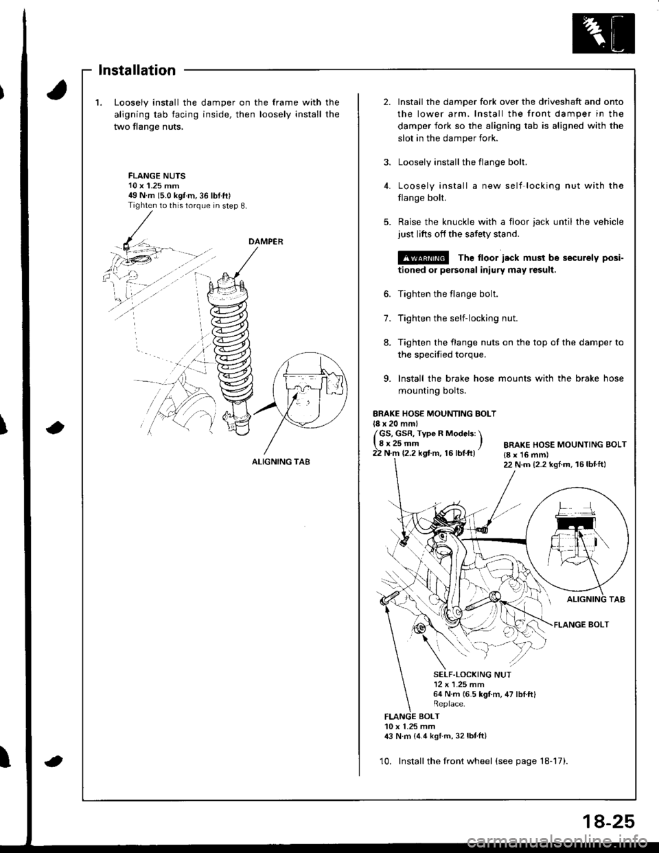
1.Loosely install the
aligning tab facing
two flange nuts,
damper on the frame with
inside, then loosely install
the
the
2.Install the damper fork over the driveshaft and onto
the lower arm. Install the front damper in the
damper fork so the aligning tab is aligned with the
slot in the damper fork.
Loosely install the flange bolt.
Loosely install a new self locking nut with the
flange bolt.
Raise the knuckle with a floor jack until the vehicle
just lifts off the safety stand.
@ The ltoor jack must be securely posi-
tioned or personal iniury may result.
Tighten the flange bolt.
Tighten the self-locking nut.
Tighten the flange nuts on the top of the damper to
3.
FLANGE NUTS10 x'1.25 mm49 N m 15.0 kgt m,36 lbtft)Tighten to this torque in step 8.
4.
5.
6.
7.
8.
the specified torque.
9. lnstall the brake hose mounts with the brake hose
mounting bolts.
ERAKE HOSE MOUNTING BOLT18 x 20 mml
/GS, GsR, Type R Models: \lgr25-- ,22 N.m 12.2 kgt m, 16 lbf.ft)BRAKE HOSE MOUNTING BOLT{8 x 16 mm)22 N.m {2.2 kgl.m, 16lbtft}
FLANGE BOLT
SELF.LOCKING NUT12 x L25 mm64 N.m (6.5 kgt m, 47 lbI.ftl
BOLT10 x 1.25 mm,|:} N.m {4.4 kstm, 32lbtft}
10. Install the front wheel (see page 18-17).
DAMPER
ALIGNING TA8
lnstallation
8-25
Page 1134 of 1680

Starting System
Starter Test (cont'dl
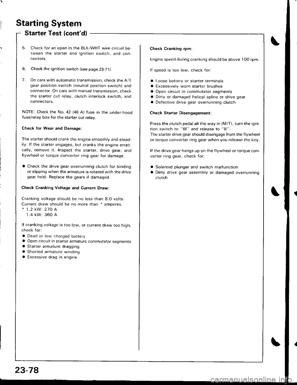
Check Cranking rpmr
Engine speed during cranking should be above 1OO rpm.
lJ speed is too low, check for:
a Loose batlery or starter terminals
a Excessively worn starter brushes
a Open circuit in commutator segments
a Dirty or damaged helical spline or drive gear
a Defective drive gear overrunning clutch
Check Starter Disengagement:
Press the clutch pedal all the way in (M/T), turn rhe igni
tion switch to "lll" and release to "11".
The starter drive gear should disengage from the flywheel
or torque converter ring gear when you release the key.
It the drive gear hangs up on the flywheel or torque con-
verter ring gear, check for:
a Solenoid plunger and switch mallunction
a Dirty drive gear assembly or damaged overrunning
clutch
5. Check for an open in the BLK/WHT wire circuit be
tween the starter and ignition switch, and con-
necrors,
6. Check the ignition switch (see page 23-71).
7. On cars with automatic transmission, check the A/Tgear position switch (neutral position switch) and
connector. On cars with manualtransmission, check
the starter cut relay, clutch interlock switch, and
connectors.
NOTE: Check the No. 42 (40 A) fuse in the under,hoodfuse/relay box for the starter cut relay.
Check Jor Wear and Damage:
The starter should crank the engine smoothly and stead,ily. lf the starter engages, but cranks the engine errati
cally, remove it. Inspect the starter, drive gear, andllywheel or torque converter ring gear lor damage.
a Check the drive gear overrunning clutch for binding
or slipping when the armature is rotated with the drivegear held. Replace the gears i{ damaged.
Check CJanking Voltage and Current Draw:
Cranking voltage should be no less than 8.O volts.
Current draw should be no more than * amperes.* 1.2 kW: 27O A
1 .4 kW: 360 A
It cranking voltage is too low, or current draw too high,check for:
a Dead or low charged batterya Open circuit in starter armature commutator segmentsa Starter armalure dragging
a Shorted armature windinga Excessive drag in engine
Page 1141 of 1680
BRUSHES
Startel Field Winding Test
Check for continuity between the brushes. lf there's
no continuity. replace the armature housing.
Check for continuily between each brush and the ar-
mature housing (ground). lf there is continuity,
replace the armature housing.
Overrunning Clutch InsPection
Slide the overrunning clutch along the shaft.
Does it move freely? It not, replace it.
Rotate the overrunning clutch both ways.
Does it lock in one direction and rotate smoothly in
reverse? It it does not lock in either direction or it
locks in both directions, repl8c€ it,
lf the starter drive gear is worn or damaged, replace
the overrunning clutch assembly; the gear is not
available separately.
Check the condition ot the flywheel or torque con-
vener ring gear it the starter drive gear teeth are
damaged.
/
J
CLUTCH G€AR
DRIVE GEAR
23-85
l'l- ,-----_ -'l
Page 1656 of 1680

{b
Design Specifications
x1: At 6,000 engine rpm*2: At 7,600 engine rpm
0
(cont'd)
{
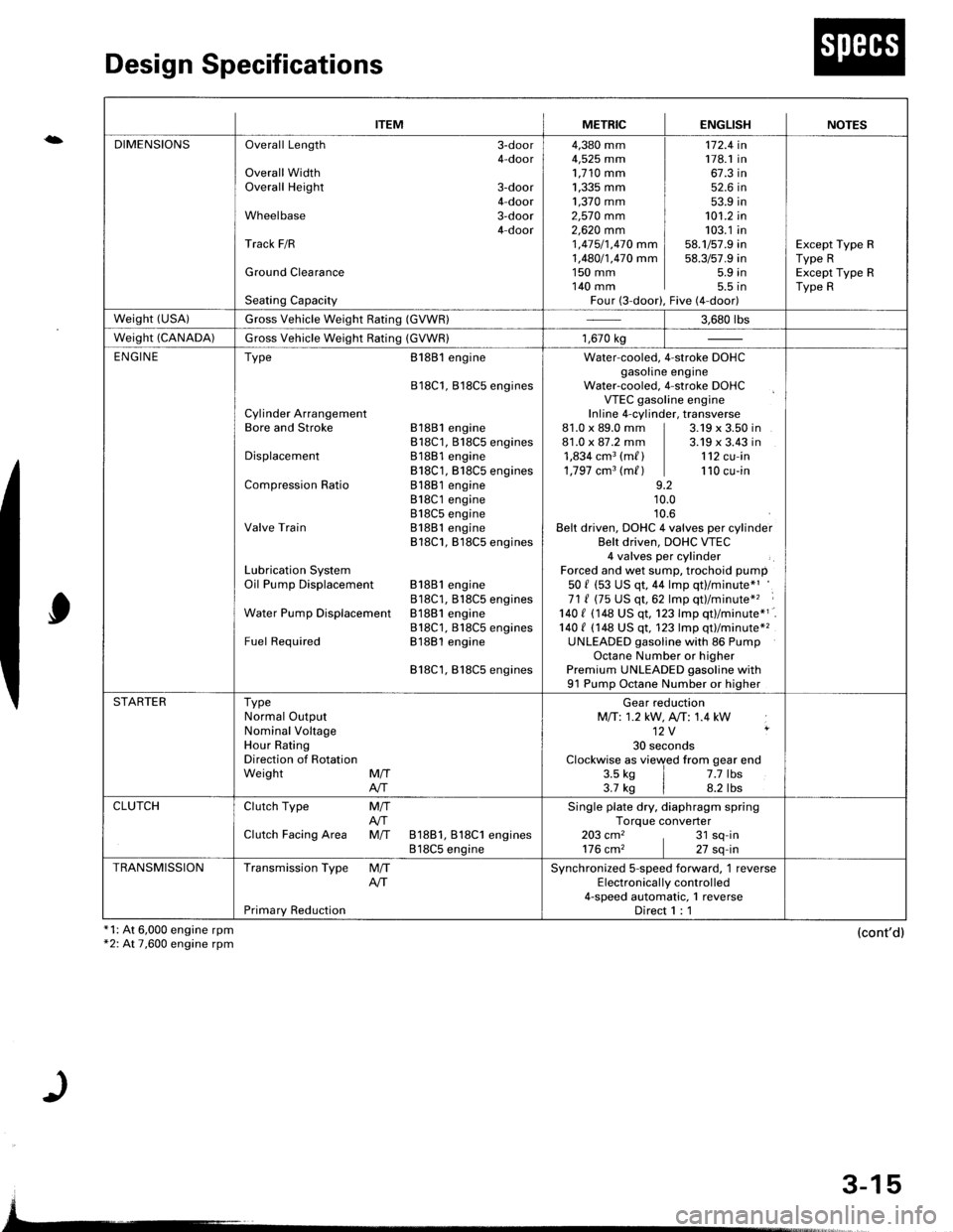
ITEMMETRICENGLISHNOTES
DIMENSIONSOverall Length 3-door4-doorOverall WidthOverall Height 3-door4-doorWheelbase 3-door4-doorTrack F/R
Ground Clearance
Seating Capacity
4,380 mm4,525 mm1,710 mm1,335 mm ]1,370 mm ]2,57O mm2,62O mm 11 ,415/1,470 mm I1,480/1,470 mm I1s0 mm I140 mm IFour (3-door),
172.4 in178.1 in67.3 in52.6 in53.9 in101.2 in103.1 in58.1/57.9 in58.3/57.9 in5.9 in5.5 tnFive (4-door)
Except Type RType RExcept Type RType R
weisht (usA)Gross Vehicle Weight Rating (GVWR)3.680 rbs
Weight (CANADA)Gross Vehicle Weight Rating (GVWR)1,670 kg
ENGINEType
Cylinder ArrangementBore and Stroke
Displacement
Compression Ratio
Valve Train
Lubrication SystemOil Pump Displacement
Water Pump Displacemenl
Fuel Required
8188l engine
818C1, Bl8C5 engines
81881 engine818C1, 818C5 engines81881 engine818C1, B18C5 engines81881 engine818C1 engine818C5 engineB1881 engine818C1, B18C5 engines
81881 engine818C1, B18CS enginesB1881 engine818C1, 818C5 enginesB1881 engine
818C1,818C5 engines
Water-cooled. 4-stroke DOHCgasoline engineWater-cooled, 4-stroke DOHCVTEC gasoline engineInline 4-cylinder, transverse81.0 x 89.0 mm | 3.19 x 3.50 in81.0 x 87.2 mm | 3.19 x 3.43 in1,834 cm3 (m/ ) | 112 cu-in1,797 cm3 (m/ ) | 110 cu-in9.210.010.6Belt driven, DOHC 4 valves per cylinderBelt driven, DOHC VTEC4 valves per cylinderForced and wet sump, trochoid pump50 f (53 US qt, 44 lmp qt)/minute*'71 ( (75 US qt,62 lmp qt)/minute*'� :
140 I 1148 US qt. 123 lmp qtl/minute*1140 t (148 US qt, 123 lmp qt)/minute*2UNLEADED gasoline with 86 PumpOctane Number or higherPremium UNLEADED gasoline with91 Pump Octane Number or higher
STARTERTypeNormal OutputNominal VoltageHour RatingDirection of RotationWeight MffAIT
Gear reductionMfi:1.2 kW, A,/T: 1.4 kW12V ,
30 secondsClockwise as viewed from gear end3.5 ks | 7.7 lbs3.7 kg | 8.2 lbs
CLUTCHClutch Type
Clutch Facing Area
M/TAfiM/T 81881, 818C1 engines818C5 engine
Single plate dry, diaphragm springTorque converter203 cm2 , 31 sq-in176 cm2 | 27 sq-in
TRANSMISSIONTransmission Type
Primary Reduction
M/TAITSynchronized S-speed forward, 1 reverseElectronical ly control led4-speed automatic, 1 reverseDirect 1 : 1
3-15
Page:
< prev 1-8 9-16 17-24