- Hub Bearing Unit
Removal
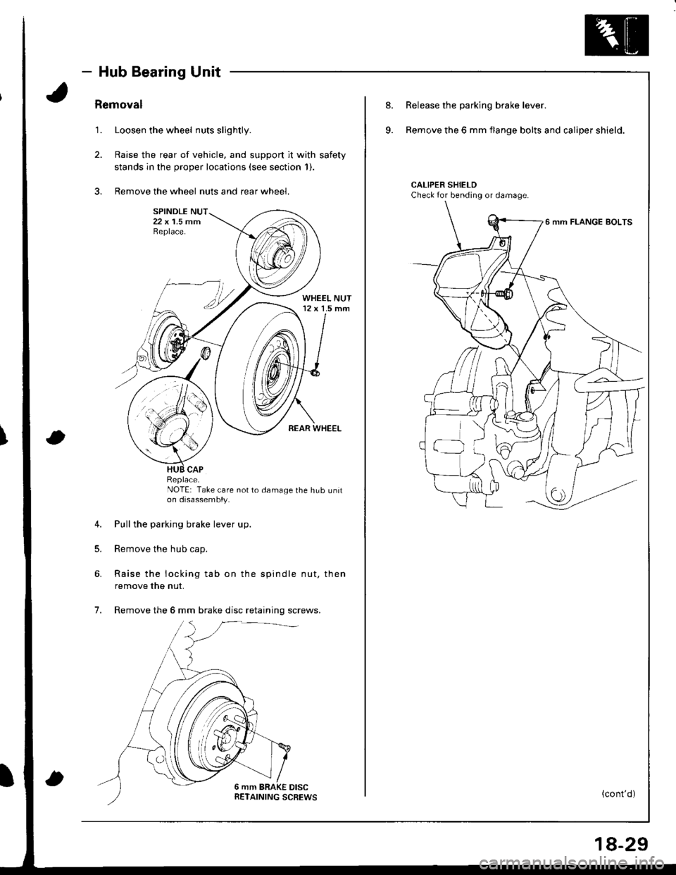
1. Loosen the wheel nuts slightly.
2. Raise the rear of vehicle, and support it with safety
stands in the proper locations (see section 1).
3. Remove the wheel nuts and rear wheel.
NOTE: Take care not to damage the hub uniton disassembly.
4. Pull the parking brake lever up.
5. Remove the hub cap.
6. Raise the locking tab on the spindle nut, then
remove the nut.
7. Remove the 6 mm brake disc retaining screws.
Replace.
8.
9.
Release the parking brake lever.
Remove the 6 mm flange bolts and caliper shield.
CALIPER SHIELDCheck for bending or damage.
6 mm FLANGE BOLTS
(cont'd)
18-29
- Hub Bearing Unit
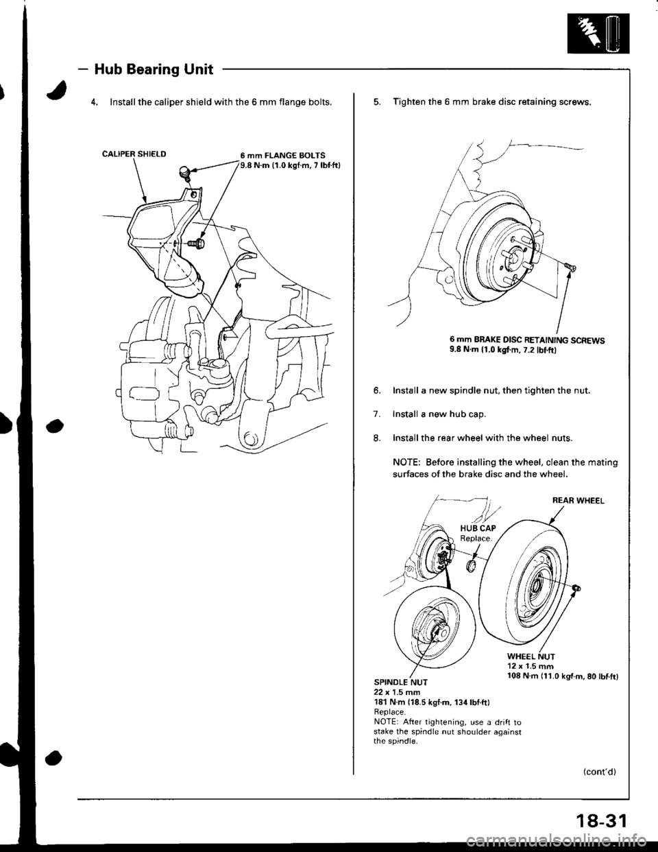
4. Install the caliper shield with the 6 mm flange bolts.
6 mm FLANGE BOLTS9.8 N.m 11.0 kgI.m, 7 lbr.ftl
5. Tighten the 6 mm brake disc retaining screws,
6 mm BBAKE D|SC RETA|NTNG SCREWS9.8 N.m 11.0 kgf.m, 7.2 tbtftl
6. Install a new spindle nut, then tighten the nut.
7. Install a new hub cap.
8. Install the rear wheel with the wheel nuts.
NOTE: Before installing the wheel, clean the mating
surfaces of the brake disc and the wheel.
REAR WHEEL
WHEEL12 x 1.5 mm
SPINDLE NUT22 x 1.5 mm181 N.m {18.5 kgt.m. 134lbl.ftl
108 N.m 111.0 kg'f.m.80 lbf.tr)
Beplace.NOTE: After tightening, use a drift tostake the spindle nut shoulder againstthe spindle.
(cont'd)
18-31
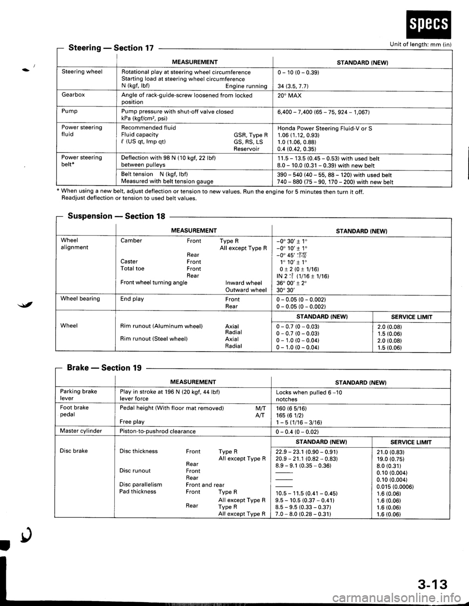
MEASUREMENTSTANDARD (NEWI
Steering wheelRotational play at steering wheel circumferenceStarting load at steering wheel circumferenceN (kgf, lbf) Engine running
0 - 10 (0 - 0.39)
34 (3.5,7 .71
GearboxAngle of rack-guide-screw loosened from lockedoosition20'MAX
PumpPump pressure with shut-off valve closedkPa (kgf/cm,, psi)6,400 - 7,400 (65 - 75, 924 - 1,067],
Power steeringfluidRecommended fluidFluid capacity GSR, Type Rf (US qt, lmp qtl cS, RS, LSReservoir
Honda Power Steering Fluid-V or S1.06 (1.12,0.93)
1.0 (1.06,0.88)
0.4 (0.42, 0.35)
Power steeringbelt*Deflection with 98 N (10 kgf,22 lbflbetween pulleys1 1.5 - 13.5 (0.45 - 0.531 with used belt8.0 - 10.0 (0.31 - 0.39) with new belt
Belt tension N (kgf, lbf)Measured with belt tension gauge390 - 540 (40 - 55, 88 - 120) with used belt740 - 880 (75 - 90, 170 - 2001with new belt
SteeringSection 17
* When using a new belt, adjust deflection or tension to new values. Run the engine for 5 minutes then turn it off.Readiust deflection or tension to used belt values.
Suspension - Section 18
BrakeSection 19
Unit of length: mm (in)
$t
MEASUREMENTSTANDARD (NEWI
WheelalignmentCamber Front Type RAll except Type RRearCaster FrontTotal toe FrontRearFront wheel turning angle Inward wheelOutward wheel
-0'30'r 1"-0' 10'r 1.-0" 45'1?:i3i1. 10'1 1.0!210!1116!,lN 2 lf (t7t6 1 1716136. 00'1 2"30'30'
Wheel bearingEnd play FrontRear0 - 0.05 (0 - 0.002)0 - 0.05 (0 - 0.002)
WheelRim runout (Aluminum wheel) AxialRadialRim runout (Steel wheel) AxialRadial
STANDARD (NEW}SERVICE LIMIT
0 - 0.7 (0 - 0.03)0 - 0.7 (0 - 0.03)0 - 1.0 (0 - 0.04)0 - 1.0 (0 - 0.04)
2.0 (0.08)
1.5 (0.06)2.0 (0.08)1.5 (0.06)
MEASUREMENTSTANDARD (NEW}
Parking brakeleverPlay in stroke at 196 N (20 kgf,44 lbf)lever forceLocks when oulled 6 -10
notches
Foot brakepedalPedal height (With floor mat removed)
Free play
M/TAtT160 (6 5/161165 rc 1nl1-5(1/16-3/16)
Master cylinderPiston-to-oushrod clearance0 - 0.4 (0 - 0.021
Disc brakeDisc thickness Front Type RAll except Type RRearDisc runout FrontRearDisc parallelism Front and rearPad thickness Front Type R
All except Type RRear Type RAll except Type R
STANDARD (NEWISERV]CE LIMIT
22.9 - 23.1 (0.90 - 0.91120.9 - 21.1 (0.82 - 0.83)
1= t (0.35-0.361
10.5 - 11.5 (0.41 - 0.45)9.5 - 10.5 (0.37 * 0.41)8.5 - 9.5 (0.33 - 0.37)7.0 - 8.0 (0.28 - 0.31)
21.0 (0.83)19.0 (0.75)
8.0 (0.31)
0.10 (0.004)
0.10 (0.004)
0.015 (0.0006)1.6 (0.06)
1.6 (0.06)1.6 (0.06)
1.6 (0.06)