1998 ACURA INTEGRA air conditioning
[x] Cancel search: air conditioningPage 1006 of 1680
Blower Unit
Replacement
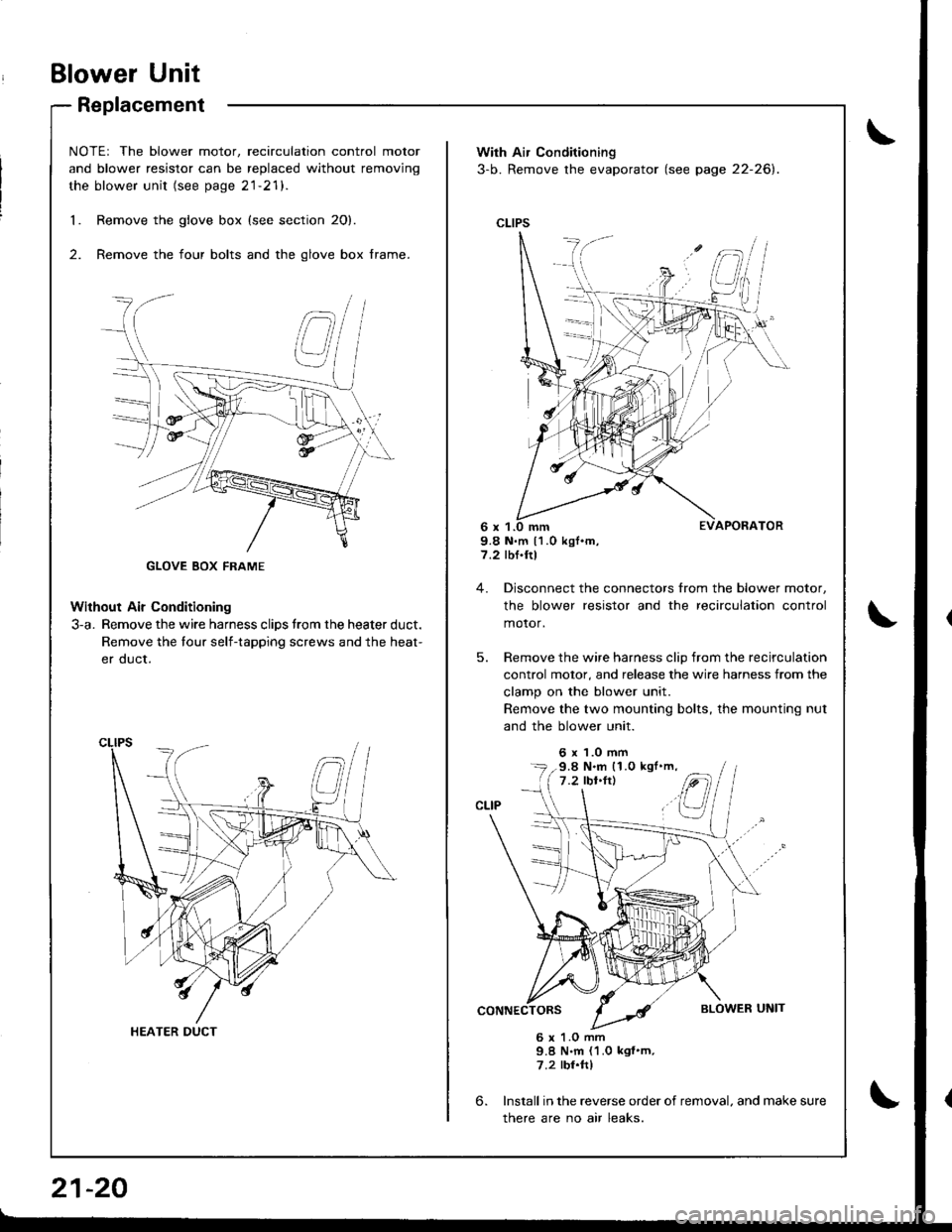
NOTEr The blower motor, recirculation control motor
and blower resistor can be replaced without removjng
the blower unit (see page 21-21).
Remove the glove box {see section 20}.
Remove the four bolts and the glove box frame.
Without Air Conditioning
3-a. Remove the wire harness clips trom the heater duct.
Remove the tour self-tapping screws and the heat-
er duct.
1.
2.
HEATER DUCT
21-20
With Air Conditioning
3-b. Remove the evaporator (see page 22-26).
CLIPS
9.8 N.m 11.0 kgf.m,7.2 rbf.ftl
4. Disconnect the connectors from the blower motor,
the blower resistor and the recirculation control
motor,
5. Remove the wire harness clip from the recirculation
control motor, and release the wire harness from the
clamp on the blower unit.
Remove the two mounting bolts, the mounting nut
and the blower unit.
6 x 1.0 mm
6.
6 x 1.O mm9.8 N.m (1.0 kgf'm,7.2 rbr.ftl
Install in the reverse order of removal. and make sure
there are no air leaks.
9.8 N.m (1.0 kgl'm,
Page 1020 of 1680
lllustrated Index
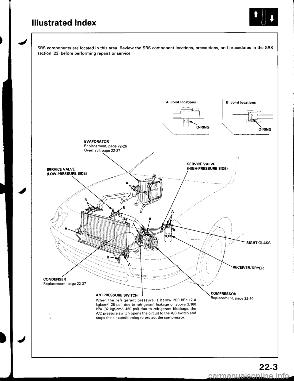
JSRS components are located in this area. Review the SRS component locations, precautions, and procedures in the SRS
section (23) before performing repairs or service.
EVAPORATORReplacement, page 22,26Ove.haul. page 22-27
SERVICE VAI-VE
ILOW.PRESSURE SIDE)
SERVICE VALVE{HIGH.PRESSUEE SIDE}
SIGHT GLASS
CONOENSERReplacement, page 22 37
A/C PRESSURE SWITCHCOMPRESSOR
When the refrigerant pressure is below 200 kPa (2.0
kgllcm,, 28 psi) due to refrigerant leakage or above 3,'100kPa (32 kgtcm,,460 psi) due to relrigerant blockage, theA,/C pressure sw;tch opens the circuit to the A,/C switch andstops the air conditioning to protect the compressor.
page 22-30
22-3
Page 1023 of 1680
Description
Outline
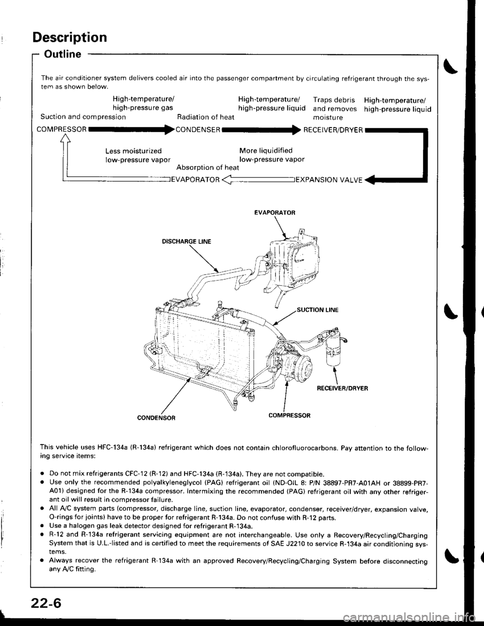
The air conditioner system delivers cooled air into the passenger companment by circulating retrigerant through the sys-
tem as shown below.
High-temperature/ H ig h-tem peratu rel Traps debris High-temperature/high-pressure gas high-pressure liquid and removes high-pressure liquidSuction and compression Radiation of heat moisture
covpnEsson -tl4con oetsen -rr{ REcEIvER/DRvER
More liqu idified
low-pressure vapor
Absorption of heat
Less moisturized
low-pressure vapor
EVAPORATOR -TEXPANS|ON VALVE
EVAPORATOR
CONDENSOR
This vehicle uses HFC-134a (R-134a) refrigerant which does not contain chlorofluorocarbons. Pay attention to the follow-ing service items:
. Do not mix refrigerants CFC-12 (R-12) and HFC-134a (R-134a). They are not compatible.. Use only the recommended polyalkyleneglycol (PAG) refrigerant oil (ND-OIL 8: P/N 38897-PR7-A01AH or 38899-PR7-A01) designed for the R-134a compressor. Intermixing the recommended (PAG) refrigerant oil with any other refriger-ant oil will result in compressor failure.
. All AVC system parts (compressor, discharge line, suction line. evaporator, condenser, receiver/dryer, expansion valve.O-rings for joints) have to be proper for refrigerant R-134a. Do not confuse with R-12 parts.
. Use a halogen gas leak detector designed for refrigerant R-134a.. R-12 and R-134a refrigerant servicing equipment are not interchangeable. Use only a Recovery/Recycling/ChargingSystem that is U.L.-listed and is certified to meet the requirements of SAE J2210 to service R-134a air conditioning sys-tems.
. Always recover the refrigerant R-134a with an approved Recovery/Recycling/Charging System before disconnectingany Ay'C fitting.
22-6
Page 1038 of 1680
A/C Service Tips and Precautions
The air conditioner system uses HFC-134a (R-134a) refrigerant and polyalkyleneglycol {PAG) refrigerant oil (ND-OlL 8: P/N
38897-PR7-A01AH or 38899 - PR7 - A01), which are not compatible with CFC-12 (R-12) refrigerant and mineral oil. Do not
use R-12 refrigerant or mineral oil in this system. and do not attempt to use R-12 servicing equipment; damage to the air
conditioner system or your servicing equipment will result.
Use only service equipment that is U.L.-listed and is certified to meet the requirements of SAE J2210 to remove R-l34a
from the air conditioner system.
CAUTION: Exposure to air conditioner refrigerant and lubricant vapor ot mist can irritate eyos, nose.nd throat, Avoid
breathing th€ air conditionsr rofrigerant 8nd lubricant vapo. or mist.
lf accidental system discharge occurs, ventilate work area before resuming service.
R-134a service equipment or vehicle air conditioner systems should not be pressure tested or leak tested with comp.essed
atf,
@ some mixtures ol air and R-13i[a have been shown to be combustible at olevat6d pre3sures and cln resuh
in fire or explosion causing iniury or property damage. Nover uso compressed air to prossure te3t R-13,[8 service equip-
ment or vehicle air condition6r systems.
Additional health and safety information may be obtained from the refrigerant and lubricant manufacturers,
1. Always disconnect the negative cable from the battery whenever replacing air conditioning parts.
2. Keep moisture and dust out of the system. When disconnecting any lines. plug or cap the Jittings immediately; don't
remove the caps or plugs until just before you reconnect each line.
3. Before connecting any hose or line, apply a few drops of refrigerant oilto the O-ring,
4. When tightening or loosening a fitting, use a second wrench to support the matching fitting.
5. When recovering the system. use a R-134a refrigerant Recovery/Recycling/Charging System; don't release refrigerant
into the atmosphere.
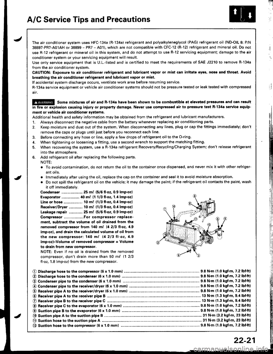
6. Add refrigerant oil after replacing the following parts.
NOTE:
. To avoid contamination, do not return the oil tothe container once dispensed, and never mix itwith other refriger-
ant oils.
.lmmediatelyafterusingtheoil,replacethecaponthecontainerandseal it to avoid moisture absorption.
. Do notspillthe refrigerant oil onthevehicle; it maydamagethe painu itthe refrigerant oil contacts the paint, wash
it off immediately.
Coodansor ..-.-.-............. 25 mt (5/6 ll.oz. 0.9 lmp.oz)
Evaporator ................. ,[0 m/ (1 1/3 fl.oz, 1.4 lmp.ozl
Line or hoss .................. 10 m? {1/3fl.oz, 0.'l lmp.ozl
Receiver/Dryer ............. 10 m/ (1/3 fl.oz, 0.4 lmp.ozl
Leskage repair .............25 m/ {5/6 fl.oZ, 0.9 lmp.oz)
Compreigor .....,......,..Fo1 comprgssor replace-
ment, subtract the volum€ of oil drained from the
removed comprassor lrom l/t{l m[ (1 213 ll.oz, 1,9
imp'ozl, and drain the calculated volume ot oil from
the new compressor: 140 m/ 11 213 ll.oz, 1.9
imp.oz)-Volum€ oI removed comprsssor = Volum€
to drain trom n€w compressor.
NOTE: Even if no oil is drained from the removed
comDressor, don't drain more than 50 m{ {1 2/3
fl.oz. 1.8 lmp.oz) from the new compressor.
O Dischargo hoso to the compressol (6 x 1.0 mml............................... 9.8 N'm (1.0 kgf.m, 7.2 lbf'ftl
@ Di3charge hose to the condenser {6 x 1,0 mm)
@ Condonser pipe to the condenser (6 x '1.0 mml
9.8 N'm (1.0 kgl.m, 7.2 lbf.ftl
.. 9.8 N.m (1.0 kgf.m,7.2lbl.ltl
@ Condenser pipe to the rec€ivor/dryer (6 x 1.0 mml
O Receiver pipe A to th8 recoiver/dryer (6 x 1.0 mml
@ Receiyar pipe A to lhe receiver pipe B ,...........
O Receiver pipe B to th8 .ocoiver pipe C ............
@ R€ceiver pipe C to the evaporator 16 x 1.0 mm)
@ Suction pipe B to th€ evaporator {6 x 1.0 mm) .......,.
@ Suqtion pipe A to the suction pipe B
O Suction hose to the suction pipe A ...........,.
@ Suction hose to the compressor 16 x 1.0 mml
9.8 N.m (1.0 kgf.m, 7.2 lbf.ftl
9.8 N'm (1.0 kgf.m, 7.2 lbf.fr)
13 N.m (1.3 kgf.m. 9.4 lbf.ft)
13 N.m (1.3 kgf.m,9.'l lbf.ftl
9.8 N.m (1.0 kgt m. 7.2 lbf.ftl
...... 9.8 N.m {1.0 kqf'm, 7.2 lbf.ft)
........ 31 N'm (3.2 kgf.m, 23 lbf.ft)
............ 31 N.m (3.2 kgf.m,23 lbtft)
..................... 9.8 N.m {r.0 kgf.m, 7.2 lbtft)
22-21
Page 1041 of 1680
A/C System Service
Performance Test
The performance test will help determine if the air con,
ditioner system is operating within specifications.
Use only service equipment that is U.L.-listed and is cer,
tified to meet the requirements of SAE J2210 to remove
HFC-134a (R-134a) from the air conditioner svstem.
CAUTION: Exposure to air conditioner retrigerant and
lubricant vapor or mist can irritate eyes, nose and
throat. Avoid breathing the air conditioner refrigerant
and lubricant vapor or mist.
lf accidental system discharge occurs, ventilate work
area before resuming service.
R-134a service equipment or vehicle air conditioner sys-
tems should not be pressure tested or leak tested with
compressed arr.
@ some mixtures of air and R-134a have
been shown to be combustible at elevated Dressures
and can result in fire or explosion causing iniury orproperty damage. Never use compressed air to pressure
test R-134a service equipment or vehicle air conditioner
systems.
Additional health and safety information may be
obtained from the refrigerant and lubricant manufactur-
ers.
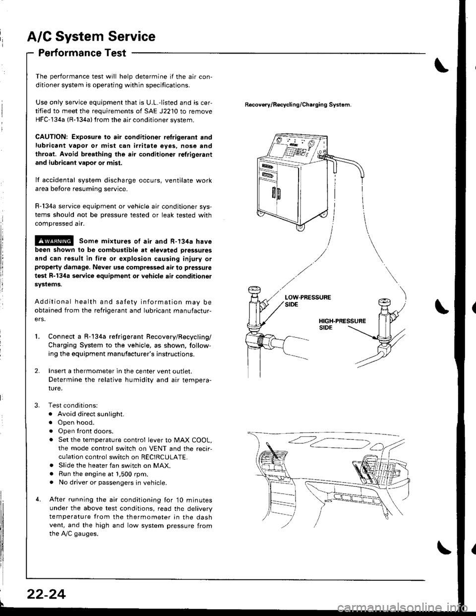
Connect a R-134a refrigerant Recovery/Recycling/
Charging System to the vehicle, as shown, follow-
ing the equipment manufacturer's instructions.
Insen a thermometer in the center vent outlet.
Determine the relative humidity and air tempera-
IUre.
Test conditions:
. Avoid direct sunlight.
. Open hood.
. Open lront doors.
. Set the temperature control lever to MAX COOL,
the mode control switch on VENT and the recir-
culation control switch on RECIRCULATE.. Slide the heater fan switch on MAX.. Run the engine at 1.500 rpm.. No driver or passengers in vehicle.
After running the air conditioning for'10 minutes
under the above test conditions, read the delivery
temperature from the thermometer in the dashvent, and the high and low system pressure from
the A,/C gauges.
Recovo.v/Recycling/Charging System.
LOW.PRESSURE
l
22-24
Page 1057 of 1680
J
Electrical
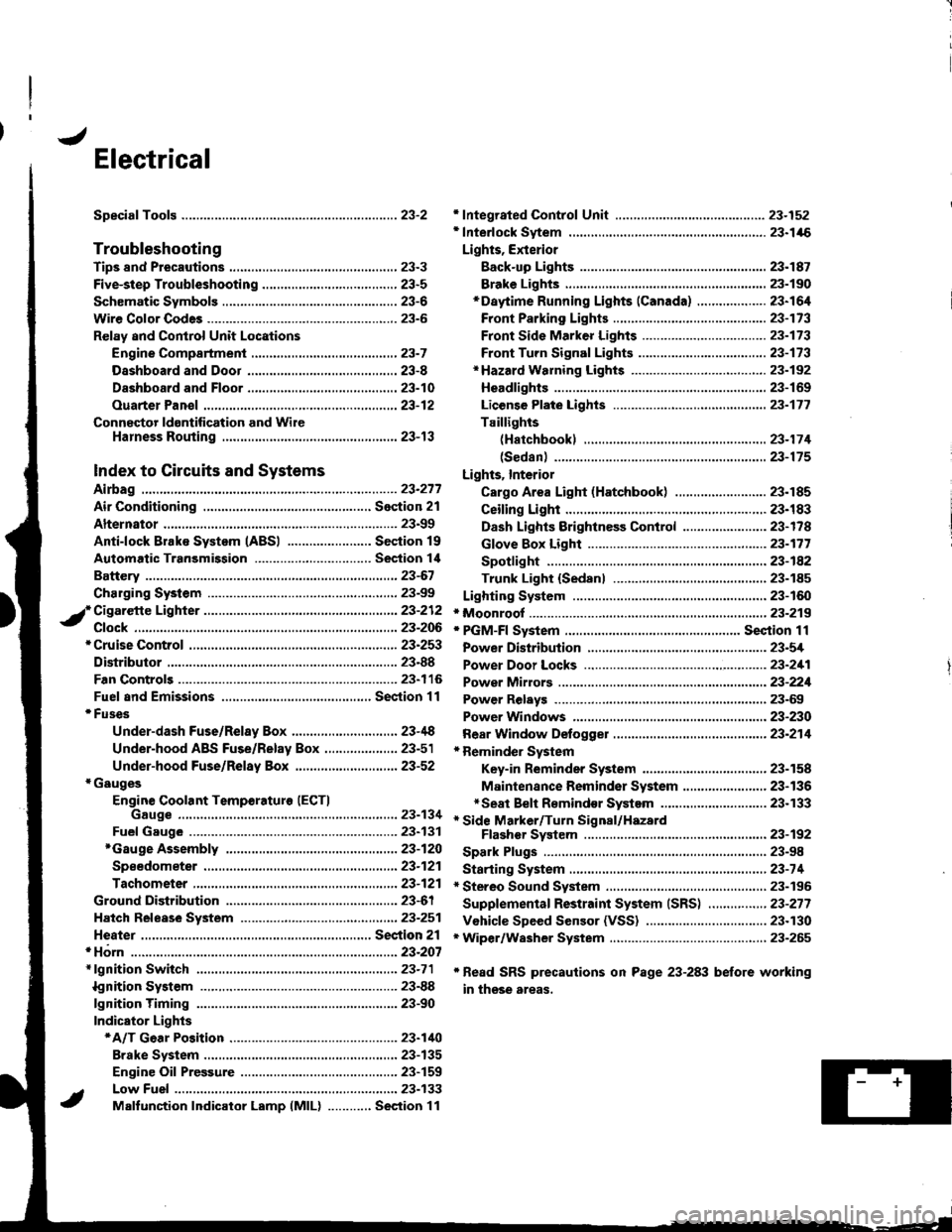
Speciaf Toofs ..........................23-2
Troubleshooting
Tips 8nd Precautions .......................,..,.,.,.,.,......,..., 23-3
Five-step Troubleshooting ............,......,.,.,...,..,....., 23-5
Schsmatic Svmbols ...............23-6
Wire Color Code3 .. ................. 23-6
Relay and Control Unit Locations
Engine Compartment ......,.,.................,.,.,.,.,.,,,, 23-7
Dashboard and Door .........,...........,.....,.,....,.,.... 23-8
Dashboard and Floor ......................................... 23-10
Ouarter Pan€f .,,.,...,.,..,...,,,23-12
Connector ldontification and WireHarness Routing ......,.,......23-'13
Index to Circuits and Systems
Airbag
* Integrated Control Unit .....,.,.,.....23-152* Interlock Sytem .,...,.,...........,. 23.146
Lights, Exterior
Eack-up LighB ..................23.187
Brake Ligh$ ......................23-190*Daytime Running Lights (Canada) ................... 23"164
Front Parking Lights .......................................... 23-173
Front Side Marker Lights .................................. 23-173
Front Turn Signal Lights ..................-.......,...,.,. 23-173* Hazard Warning Lights ....................,........,....... 23-192
Headlights.....23-169
23-253 powerDistribution..................... 23-5/r
Air Conditioning.....,....... Soction 21
Alternator ..........,................... 23.99
iCigarette Lighter .........23-212
*Cruise Control
Distributor
'.'.,.'.'.,.'...,,,,.,''.'.,.',.'''.' 23.277
.............................. 23.88
................... 23-90lgnition Timing ......
Indicator Lights
Key-in Reminder System
Maintenance Reminder System*Seat Belt R€mindor System .,...........................* Side Marker/Turn Signal/HazardFlashcr Svstem .................23-192
Spark Plugs ............................23-98
Starting System .....................23-74* Stereo Sound System ...,......,..........,...,......,.,.,.,..,., 23-196
Supplemental Restraint System (SRS) ................ 23-277
Vshicle Speed Sensor (VSS) ................................. 23.130r Wiper/Washer System .........................................., 23-265
*Read SRS precautions on Psge 23-283 before working
in those areas,
23-154
23.136
23"133
Page 1478 of 1680
A/C Gompressor Controls (conrd)
- How the Circuit Works
Battery voltage is supplied through fuse 56 to the
A,/C compressor clutch relay contacts at all times.
With the ignition switch in ON (ll), voltage is applied
to the coil of the A,/C compressor clutch relay
through fuse 17. When you push the A,/C switch
ON, and the heater fan switch is in posation 1, 2, 3,
or 4, a "ground" input is provided to the engine or
powertrain control module (ECM or PCM) through
the A,/C thermostat and the A,/C pressure switch.
The A,/C compressor clutch relay is grounded by the
engine or powertrain control module (ECM or PCM).
When energized, the A,/C compressor clutch relay
allows battery voltage to turn on the A,/C
comDressor clutch,
The A,/C ON indicator light comes on when the A"/C
system is requested.
A,/C Thermostat
The A,/C thermostat is located on the evaoorator
housing. The AJC thermostat turns off the A,/C
compressor clutch if the temperature at the
evaporator goes below 3'C (37'F). This prevents
condensation from freezing on the evaporator fins
and blocking the air delivery into the passenger
compartment. The blower motor will keep running
when the sensor lurns off the compressor.
A,/C Pressure Switch
The A,/C pressure switch is located in the condenser
outlet line where refrigerant is in a high
temperature/high pressure liquid state. The switch
will sense abnormally high or low pressure, and
open the circuit. This removes ground, and the
compressor will stop running.
Refer to the Service Manual (Section 22,
Air Conditioning) for specific tests or
troubleshooting procedures.
62-2
Page 1655 of 1680
ng
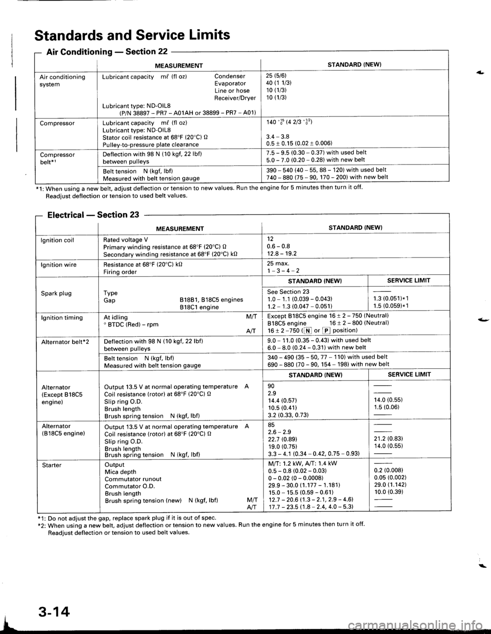
MEASUREMENTSTANDARD {NEW}
Air conditioningsystemLubricant capacity m/ (fl oz) CondenserEvaporatorLine or hoseReceiver/Drver
Lubricant type: ND-OlL8(P/N 38897 - PR7 - A01AH or 38899 - PR7 - A01)
25 1516l40 (1 1/3)10 (1/3)
10 (1/3)
CompressorLubricant capacity m/ (fl oz)Lubricant type: ND-OlL8Stator coil resistance at 68'F (20"C) OPulley-to-pressure plate clearance
140'�trs 142B'�y'�l
3.4 - 3.80.5 I 0.15 (0.02 1 0.006)
Compressorbelt*rDeflection with 98 N (10 kgf. 22 lbf)between pulleys
7.5 - 9.5 (0.30 - 0.37) with used belt5.0 - 7.0 (0.20 - 0.281 with new belt
Belt tension N (kgf, lbf)Measured with belt tension gauge390 - 540 (40 - 55, 88 - 120) with used belt740 - 880 (75 - 90, 170 - 200) with new belt
*1: When using a new belt, adjust deflection or tension to new values. Run the engine for 5 minutes then turn it off.
Standards and Service Limits
Air Conditionins - Section 22
Readjust deflection or tension to used belt values.
Electrical - Section 23
f1: Do not adjust the gap, replace spark plug if it is out of spec'*2: When using a new belt. adjust deflection or tension to new values. Run the engine for 5 minutes then turn it off.
Readjust deflection or tension to used belt values.
a.
t-
MEASUREMENTSTANDARD (NEW}
lgnition coilRated voltage VPrimary winding resistance at 68"F (20'C) O
Secondary winding resistance at 68'F (20"C) k0
120.6 - 0.812.8 - 19.2
lgnition wireResistance at 68'F (20'C) k0Firinq order
25 max.1-3-4-2
Spark plugI ypeGap B18B1, 818C5 engines818C1 engine
STANDABD {NEWISERVICE LIMIT
See Section 231.0 - 1.1 (0.039 - 0.04311.2 - 1.3 (0.047 - 0.051)i-= roru',t.',1.5 (0.0591* 1
lgnition timingAt idling' BTDC (Red) - rpmM/T
AIT
Except 818C5 engine 16 ! 2 -750 (Neutral)
818C5 engine 16 t 2 - 800 (Neutral)
16!2-750 t1r{ or p position)
Alternator belt*2Deflection with 98 N (10 kgf, 22 lbf)between pulleys9.0 - 1 1.0 (0.35 - 0.43) with used belt6.0 - 8.0 (0.24 - 0.31) with new belt
Belt tension N (kgf, lbflMeasured with belt tension gauge340 - 490 (35 - 50. 77 - 1'l0l with used belt
690 - 880 (70 - 90. 1 54 - 198) with new belt
Alternator(Except B18C5engine)
Output 13.5 V at normal operating temperature A
Coil resistance (rotor) at 68'F (20'C) OSlip ring O.D.Brush lengthBrush spring tension N (kgf, lbf)
STANDARD {NEW}SERVICE LIMIT
902.914.4 (0.571
10.5 (0.41)
3.2 (0.33, 0.73)
,0, to.uur1.5 (0.06)
Alternator(B l8C5 enginelOutput 13.5 V at normal operating temperature A
Coil resistance (rotor) at 68"F (20'Cl O
Slip ring O.D.Brush lengthBrush spring tension N (kgf, lbf)
852.6 - 2.922.7 rc.89119.0 (0.75)
3.3 - 4.1 (0.34 - 0.42, 0.75 - 0.93)
',to.tg14.0 (0.55)
StarterOutputMica depthCommutator runoutCommutator O.D.Brush lengthBrush spring tension (new) N (kgf, lbf)M/TA/T
Mll:1.2 kW, A"rT: 1.4 kW0.5 - 0.8 (0.02 - 0.03)0 - 0.02 (0 - 0.0008)29.9 - 30.0 (.177 - 1.18111s.0 - 15.5 (0.59 - 0.61)12.7 - 20.6 (.3 - 2.1, 2.9 - 4.6)17 .7 - 23.5 11.8 - 2.4, 4.0 - 5.3)
0.2 (0.008)
0.05 (0.002)
29.0 (1.1421
10.0 (0.39)
3-14