Page 813 of 1680
ABS Control Unit
RemovaUlnstallation
1. Remove the right quarter trim panel.
2. Disconnect the ABS control unit connectors.
3. Remove the ABS control unit.
Pulsers/Wheel Sensors
Inspection
/t
l\
I
Check the front and rear pulser for chipped or dam-
aged teeth.
Measure the air gap between tho wheel sensor and
pulser sllthe way around while rotating the pulser.
Standard: 0.4 - 1.0 mm (0.02 - 0.04 in)
NOTE: lf the gap exceeds 1.0 mm (0.04 in), the
probability is a distorted suspension arm which
should be reDlaced.
Front/R..1
L-TJ
.t-
t=
l-
Et-E_
Install the ABS control unit in the reverse order of
removal.
Start the engine, and check that the ABS indicator
goes off.
Test-drive the vehicle, and check that the ABS indi-
cator does not come on.
19-62
Page 994 of 1680

SYMPTOMREMEDY
Hot air tlow is low.Blower motor runs, but one or more
speeds are inoperative.
Follow the flowchart (see page 21-9).
Blower runs propetly.Check for the following:. Clogged heater duct
. Clogged heater outlet
. Incorrect door Position
No hot air tlowBlower motor does not run at all.Follow the flowchart {see page 21-11}
Blower motor runs.Check for the following:
. clogged heater duct
. Clogged blower outlet. Clogged heatet valve
. Faultv air mix door
. Heater valve cable adjustment lsee page 21-27].
. Air mix control cable adiustment {see page 21-27)
. Faulty thermostat (see section 10)
. Clogged evsporator (with air conditioning)
. Frozen evaDorator (with air conditioning)
Mode control motor does not run, or one or more mooes are
inoDeratave.
Follow the flowchart (see page 21-14).
Recirculation control door does not change between FRESH
and RECIRCULATE.
Follow the flowchart {see page 21-17).
Troubleshooting
Symptom Chart
NOTE: Check the engin€ coolant level and allow the engine to warm up before troubleshooting'
21-8
v
Page 1024 of 1680

J
Troubleshooting
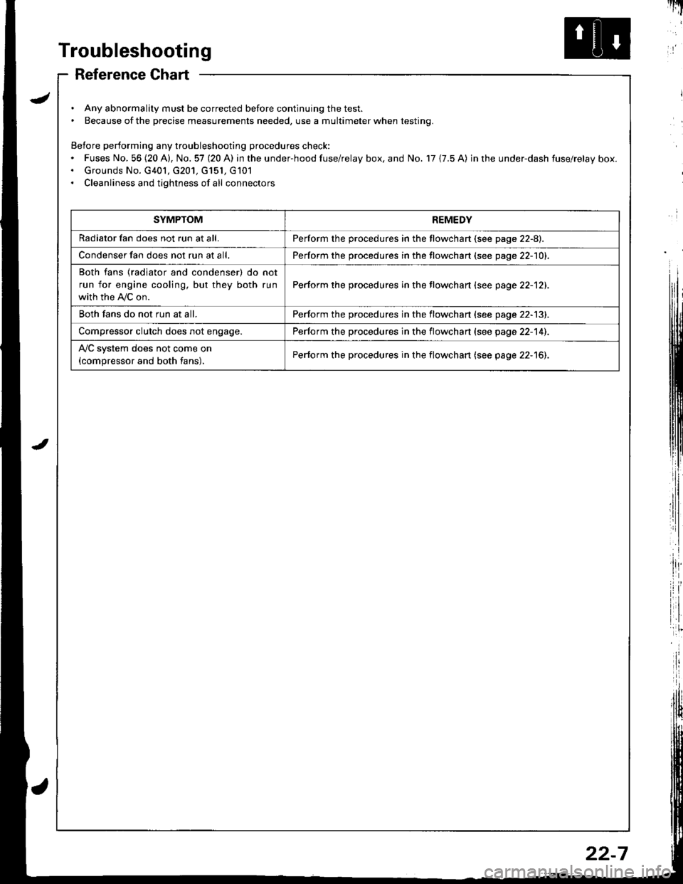
Reference Chart
. Any abnormality must be corrected before continuing the test.. Because of the precise measurements needed, use a multimeter when testing.
Before performing any troubleshooting procedures check:. Fuses No, 56 (20 A), No. 57 (20 A) in the under-hood fuse/relay box, and No. 17 {7.5 A) in rhe under-dash fuse/relay box.. Grounds No. G401, G201, G151, G101. Cleanliness and tightness of all connectors
I'IT
I
I
SYMPTOMREMEDY
Radiator fan does not run at all.Perform the procedures in the flowchart {see page 22-8).
Condenser fan does not run at all,Perform the procedures in the flowchart (see page 22-1O1.
Both fans {radiator and condenser) do not
run for engine cooling, but they both run
with the IVC on.
Perform the procedures in the tlowchart (see page 22-12).
Both fans do not run at all.Perform the procedures in the flowchart (see page 22-13).
Compressor clutch does not engage.Perform the procedures in the flowchart (see page 22-14).
l'lc system does not come on
{compressor and both fans).Perform the procedures in the flowchart (see page 22-15).
22-7
Page 1029 of 1680
Troubleshooting
Engine Coolant Temperature(ECT}Switch
Both fans (radiator and con-denserl do not run for enginecooling, but they both run withthe A,/c on.
Disconnect the engine coolanttemperature lECT) switch 2P con
Turn the ignirion switch ON ( ll).
Measure the voltage between theGRN wire terminal (+) and bodyground (-)-
Repair open in the GRN wire b€-tween the ECT switch and theunder-hood luse/rel6v box,ls there battery voltageT
Turn the ignition switch OFF andcheck for continuity in the BLKwire between the ECT switch andbody ground.
Check for en ooen in the BLKwire between the ECT switchand body ground. ll th. wire isOK, check lor poor ground atG101.
ls there continuity?
Check the temperature gauge.
Does it read above normal?
View from wire side
GRN (+)
Page 1059 of 1680

Troubleshooting
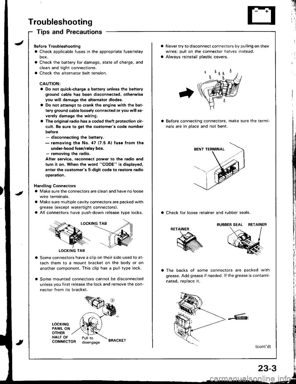
Tips and Precautions
Never try to disconnect connectors by pulling on their
wires; pull on lhe connector halves instead.
Alwavs reinstall Dlastic covers.
Before connecting connectors, make sure the termi-
nals are in Dlace and not bent.
a Check lor loose retainer and rubber seals.
The backs of some connectors are packed with
grease. Add grease if needed. lf the grease is contami-
nated, reolace it.
(cont'd )
RETAINER
K
Bef ore Troubleshooting
a Check applicable tuses in the appropriate fuse/relay
box.
Check the battery for damage, state of charge, and
clean and tight connections.
Check the alternator belt tension.
CAUTION:
a Do not quick-charge a battely unless the battery
ground cable has been disconnected. otherwise
you will damage the alternator diod€s.
a Do not attempt to crank the engine with the bat-
tery ground cable loosely connected or you willse-
verely damage the wiring.
a The originsl radio has a coded theft plotection cir-
cuit. Be sure to get the customel's code numbel
before- disconnecting the battsry.- removing the No. 47 (7.5 A) fuse from tho
under-hood luse/relay box.- removing the radio.
Atter service. leconnect Dower to the radio and
tum it on. When the word "CODE" is displayed,
enter the customer's 5-digit code to restore radio
ooeration.
Handling Connectors
a Make sure the connectors are clean and have no loose
wire terminals.
a Make sure multiple cavity connectors are packed with
grease (except watertight connectors).
a All connectors have push-down release type locks.
LOCKING TAB
LOCKING TAB
Some connectors have a clip on their side used to at-
tach them to a mount bracket on the body or on
another component. This clip has a pull type lock.
Some mounted connectors cannot be disconnected
unless you tirst release the lock and remove the con-
nector from its bracket.
LOCKINGPAWL ONOTHERHALF OFCONNECTORPull todisengageBRACKET
Page 1080 of 1680
Gonnector ldentification and Wire Harness Routing
Main Wire Harness {Right branchl
Connector or
Terminal
Number of
CavitiesLocationConnects toNot6s
c401
c402
c403
c404
c405
c407
c408
c409
c410
25
3
2
10
2
22
32
lo
Front passenger's door
Under right side of dash
Under right side ot dash
Under right side of dash
Under right side of dash
Behind right kick panel
Behind right kick panel
Behind right kick panel
Eehind right kick panel
Front passenger's door wire
harness (C626)
A/C diode
Heater sub-harness A (C672)
Heater sub-harness A (C671)
Service check connector
ABS sub-harness (C7O l)
Engine control module {ECfM)Engine control module lECM)Engine contfol module (ECM)
23-24
Page 1133 of 1680

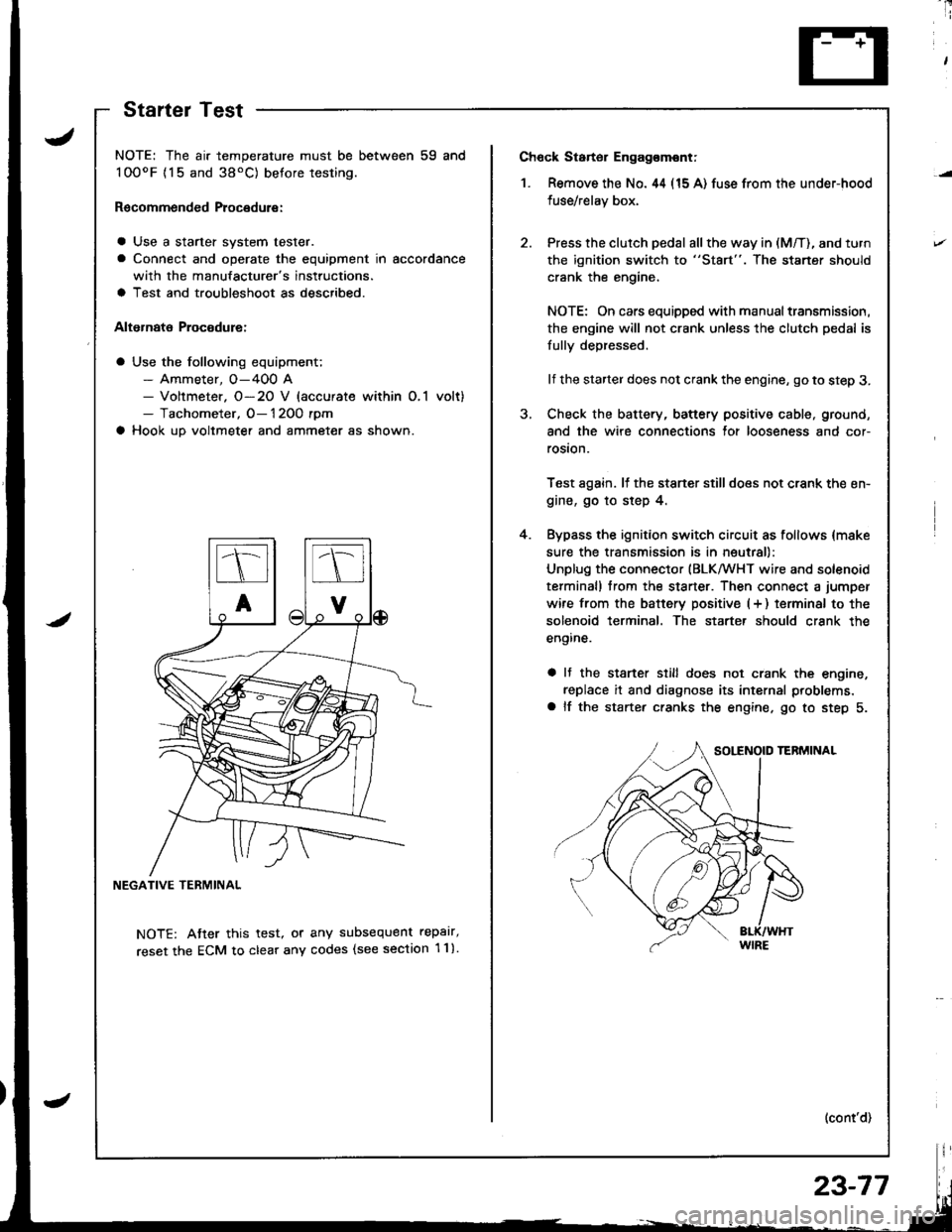
Ch6ck Starter Engag€mont;
1. Remove the No. 44 (15 A) fuse from the under-hood
fuse/relay box,
Press the clutch pedal all the way in (M/T), and turn
the ignition switch to "St8rt". The staner should
crank the engine,
NOTE: On cars equipped with manual transmission,
the engine will not crank unless the clutch pedal is
fully depressed.
lf the starter does not crank the engine, go to step 3.
Check the battery, battery positive cable, ground,
and the wire connections for looseness and cor-
rosion.
Test again. lf the stsner stilldoes not crank the en-
gine, go to step 4.
Bypass the ignition switch circuit as follows {make
sure the transmission is in neutral)
Unplug the connector (BLKMHT wire and solenoid
terminal) trom the staner. Then connect a jumper
wire from the batterv positive (+ ) terminal to the
solenoid terminal. The starter should crank the
engine.
a It the stsrter still does not crank the engine,
replace it and diagnose its internal problems,
a lf the starter cranks the engine. go to step 5.
(cont'd)
4.
NOTE: The air temperature must be between 59 and
100oF {15 and 38'C) betore testing.
Recommended Procedure:
a Use a starter system tester.
a Connect and operate the equipment in accordance
with the manufacturer's instructions.
a Test and troubleshoot as described.
Alternate Procodure:
a Use the following equipment;- Ammeter, O-400 A- Voltmeter. O-20 V (accurate within O,1 volt)- Tachometer, O- 1 2OO rpm
a Hook up voltmeter and ammeter as shown.
NEGATIVE TERMINAL
NOTE: Atter this test, or any subsequent repalr,
reset the ECM to clear any codes (see section 1 1).
StartelTest
23-77
Page 1134 of 1680

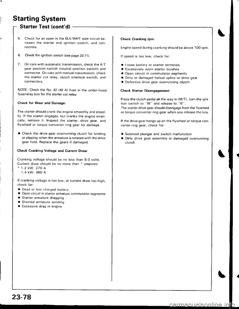
Starting System
Starter Test (cont'dl
Check Cranking rpmr
Engine speed during cranking should be above 1OO rpm.
lJ speed is too low, check for:
a Loose batlery or starter terminals
a Excessively worn starter brushes
a Open circuit in commutator segments
a Dirty or damaged helical spline or drive gear
a Defective drive gear overrunning clutch
Check Starter Disengagement:
Press the clutch pedal all the way in (M/T), turn rhe igni
tion switch to "lll" and release to "11".
The starter drive gear should disengage from the flywheel
or torque converter ring gear when you release the key.
It the drive gear hangs up on the flywheel or torque con-
verter ring gear, check for:
a Solenoid plunger and switch mallunction
a Dirty drive gear assembly or damaged overrunning
clutch
5. Check for an open in the BLK/WHT wire circuit be
tween the starter and ignition switch, and con-
necrors,
6. Check the ignition switch (see page 23-71).
7. On cars with automatic transmission, check the A/Tgear position switch (neutral position switch) and
connector. On cars with manualtransmission, check
the starter cut relay, clutch interlock switch, and
connectors.
NOTE: Check the No. 42 (40 A) fuse in the under,hoodfuse/relay box for the starter cut relay.
Check Jor Wear and Damage:
The starter should crank the engine smoothly and stead,ily. lf the starter engages, but cranks the engine errati
cally, remove it. Inspect the starter, drive gear, andllywheel or torque converter ring gear lor damage.
a Check the drive gear overrunning clutch for binding
or slipping when the armature is rotated with the drivegear held. Replace the gears i{ damaged.
Check CJanking Voltage and Current Draw:
Cranking voltage should be no less than 8.O volts.
Current draw should be no more than * amperes.* 1.2 kW: 27O A
1 .4 kW: 360 A
It cranking voltage is too low, or current draw too high,check for:
a Dead or low charged batterya Open circuit in starter armature commutator segmentsa Starter armalure dragging
a Shorted armature windinga Excessive drag in engine