Page 500 of 1680
Electrical Troubleshooting
Troubleshooting Flowchart - EIndicator Light On Gonstantly
v
ICM CONNECTOR A I26PI
\4
I
i
rlIti
Th. E indicltor ligM i! on cor.
.t.ntly Inoi blinllng) wh.n.Y.l
th. lgrhior lwftch l. ON {ll).
M...ur. D. INO Vohtg.:1. Turn tho ignition switch OFF.
2. Disconnect th€ A (26P) con-noctor from the TCM.3. Turn the ignition switch ON (ll).
4. Measure thg voltag€ bstwegnthe A17 t6rminal and bodyground.
Rapalr ahort to powar In tha wiru
b.tw..n th. A17 l.rmin.l lnd
tha gaug. .cr.mbly.
M.a3ur. ATP D. voh.g.:1. Turn the ignition switch OFF.2. Conn€ct th€ A (26P) conn€c-tor to the TCM.3. Turn th€ ignition switch ON (ll).
4, Shift to any position otherthan E position.
5. Moasure the vohag€ b€tweenthe A9 tormin.l and bodyground.
Ch.ck tor r rhort to ground in thawir. b!tw..n th. Ag tarmin.l.nd th. A/T g..r potfion lwltch.f wi.e b OK r.pllca th. A/T g.|rpolition Indacrtor.
WIRE SIDE OF FEMAI.I TERMINALS
!
{
Page 502 of 1680
Electrica I Troubleshooti n g
Troubleshooting Flowchart - Brake Switch Signal
Symptom
Shift lovar clnnot bo moved Itom
E pGition with the brske pod.l
dsoressod.
v
TCM CONNECTORS
WIRE SIDE OF FEMALE TERMINALS
v
i
lr
Check Brako Light Oporation:Deoress the brake Dedal.
Repair taulty brako switch circuit{soo 3€qtion 231.Are the brake lights ON?
Mea.ur6 STOP sw voh.ge:1. Turn the ignition switch OFF.2. Disconnect the A (26P) and B(22P) connectors lrom theTCM.3. Moasure the voltage botweenthe 812 and A13 or 426 termi-nals with the brake podal
depressed.
R€plir opon in the wire Itstwoonth€ 8'l2 torminal and bi.ke svtidt.
. 8rak6 switch signal b OK.. check lor loose TcM connoc-to]s, lf nsce$ary, sub3tituts aknown-good TcM and rochock.. lnsooct tho brake swilch circuit(soo scction 231.
, 14-86
v
{
{
Page 590 of 1680

)
I
t
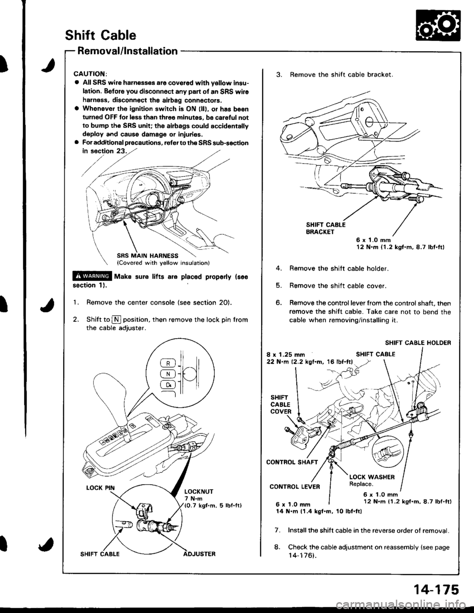
Shift Cable
Removal/lnstallation
CAUTION:
a All SRS wile ham€sses ar6 covcred with yollow insu-
lation. Befols you disconnect any part of an SRS wil6
harness, disconnect tho ailbag connoctors.
a Whenever th€ ignition switch is ON (ll), or has be€n
turned OFF for less than thr€e minutes, be caroful not
to bump tho SRS unit; tha airbags could accidentally
deploy and caus6 damags or iniuri€s.a For additional precautions, .ofer to th€ SRS sub-soction
!@! -u^" sure rrrs are praceq propeny rs€o
ssction 1).
'1. Remove the center console (see section 20).
2. Shift to N position, then remove the lock pin from
the cable adjuster.
_llr_8J.ll^/l
@i[ )l
@ll-11---l rr
LOCKNUT7 N.m10.7 kgt.m, 5 lbf.fr)
3. Remove the shift cable bracket.
6 x 1.0 mm12 N.m (1.2 kgt.m,8.7 lbf.ftl
4. Remove the shitt cable holder.
5. Remove the shift cable cover.
6. Remove the control lever from the controlshaft, then
remove the shift cable. Take care not to bend the
cable when removing/installing it.
SHIFT CABLE HOLDER
Installthe shitt cable in the reverse order ot removal.
Check the cable adjustment on reassembly {see page't 4-1761.
7.
8.
12 N.m (1.2 kgf.m,8.7 lbf.ft)
14 N.m 11.4 kgf.m, 10 lbl.ftl
14-175
Page 591 of 1680

Adiustment
CAUTION:
a All SRS wile harnesses are covered with yellow insu-
lation. Belore you disconnect any part ol an SRS wire
harness, disconnect the akbag connectors'
a Whenever the ignition switch is ON (ll), or has been
tumed OFF tol less than three minutes, be caletul not
to bump the SRS unit; the airbags could accidentally
deploy and cause damage or injuries'
a For additionalprecautions, referto the SRS sub-section
SBS MAIN HARNESS(Covered with yellow inslrlationl
$!@ rtl"t . "ure lifts are placed plope y lsee sec-
tion 1 l.
'1. Remove the center console lsee section 20)'
2. Snitt to $ position, then remove the lock pin lrom
the cable adjuster'
LOCKNUT7 N.m10.7 kgf.m, 5 lbf.fl)
t
]H
@
@
@
{l
LOCK PIN
14-176
shift cable
3. Check that the hole in the adjuster is perfectly
sligned with the hole in the shift cable'
CableToo Short
NOTE: There are two holes in the adjuster. They are
positioned 9Oo apart to allow cable adiustment in 1/4
turn Incremenrs.
4. lJ the hole is not per{ectly aligned, loosen the locknut
on the adjuster, and adiust as required.
5. Tighten the locknut to 7 N'm (0.7 kgf'm, 5lbf'ftl
6. Installthe lock pin on the adiuster. lI you feelthe lock
pin binding as Vou reinstall it, the cable is still out ot
adjustment and must be readjusted.
7. [/ake sure the lock pin is seated securely in the
aoJusrer.
8. Move the shift lever to each gear, and verify that the
automatic transaxle gear position indicator follows the
automatic transaxle gear position swatch.
9. Start the engine, and check the shift lever in allgears'
lf any gear does not work properly, refer to
troubleshooting on page 14-90 thru 93.
10. Insert the ignition key into the key cylinder on the shift
indicator panel, verify that the shift lock lever is
released.
CableToo Long
ExactAlignment
\
ADJUSTER
Page 592 of 1680
Shift Lever
Disassembly/Reassembly
a All SRS wire harnesses are covered with vellow insu-
lation. Befole you disconnect any part ol an SRS wileharness. disconnect the aitbag connectors.a Whensver the ignition switch is ON (ll), or has beenturned OFF for less than three minutes, be careful notto bump the SRS unit; the airbags could accidentallydeploy and cause damagg or iniuries.a For additional precautions, lefer to the SRS sub-sectionin section 23.
9.8 N.m {1.0 kgl.m,-7 .2 lbl.ltl
SHIFT LOCKSOLENOID
SHIFT LEVER KNOB
5 N.m 10.5 kgf.m,4lbl,Irl
AUTOMATIC TRANSAXLEGEAE POSITION SWITCHTesting, see Section 23
Apply non-hardeningthread lock sealant.
f, sxrrr rruorcaron- PANEL
PUSH KNOB
\
%
9.8 N.m 11.0 kgt.m. 7.2 lbl.ftl
@>.o"* r,"
-6{stLrcoNEGREASE
_GlSILICONE GREASE
' LOCK PIN ROD
3 N.m (O.3 kgt.m,2 tbt'trl
PARKINGPIN SWITCH
@6CONTROL
SHIFT LEVER
CONTROL SEAL
9.8 N.m (1.0 kgl.m,7 .2 tbl.ttl
)9.8 N.m l1.O kgf.m, 7.2 tbt.ft)12 N.m {1.2 kgf.m, 8.7 lbf.fr}
14-177
Page 593 of 1680
I
Shift lndicator Panel
Adjustment
CAUTION:
a All SRS wire harnesses ate covered with yellow insu-
lation. Belore you disconnect any part ol an SRS wire
harness, disconnect the airbag connectols'
a Whenever the ignition switch is ON (lll, ol has b€en
tulned OFF lo1 less than three minutes, be calgful not
to bump the SRS unit; the ailbags could accidentally
deploy and cause damage or iniulies.
a For additional precautions, lefer to the SRS sub-section
in section 23.
14-178
1.
3.
Check that the index mark on the indicator aligns
with the $ mark on the shitt indicator panel when
the transmission is in NEUTRAL
lI not aligned, remove the center console lsee sec-
tion 20).
Loosen the shift indicator panel mounting screws
and adiust by moving the Panel-
NOTE: Whenever the shift indicator panel is re-
moved, realign it as described above
INDEX MARK
a;-)\___ti_J -
@-
Page 649 of 1680

Steering
Componsnt Location
lndox
*Stooring Wheel
Removal ....
Disassombly/Ro8$.mbly
Disassombly ......
F08$€mbly
Powcr Stosring Gosrbox
R6moval
............................ 17-3
............. 17 -1
................ 17-16
............................. 17_25
17-30
17.31
.......17-21
Sy3tom DGcription
Fluid Flow Disgram
Steering Pump .............. 17-5
Stocring Goarbox ...17.8
Troublorhooting
Gonoral Troubleshooting .............................. 17.10
Noiso lnd Vibration ...... 17-1i[
Fluid Losk3
lnspoction
Installation
Powor Steering Hos6, Lino3
Roplacom€nt .................. 17.34
Powor Steoring Pump
RGplac6montlolpeqtion lnd Adiu3tm6nl
Stoo.ing Operation
Powor A$bi Chock
with v.hiclo Parked
Stcering Linkage 6nd Goarbox
Pump Bolt
17.18
17.18
17.19
17-20
17.35
t7-36
17 -37
r7-39
Inspoction
................... 17.41
Rack Guide Adiustmont ..........................-.-.-. 17 -21
Ffuid Rcplacemont ........17-21
Pump Prc&suro Chock ...,........................,..,..., 17 -22
Fluid Leakage Inrpection ............................... 17-23
Dissssembly
R€aEs€mbly
In3tallation........... 17_58
Ball Joint Boot Replacem.ni ........................ 17-61
17-U
17.49
J ,urrar*TNTAL REsrRArNr sysrEM (sRsr
The Integra SRS includes a driver's airbag located in the steering wheel hub and a passenger's airbag located inthe dashboard above the glove box,
Information necessary to safely service the SRS is included in this Service Manual. ltems marked with an asterisk(*) on the contents page include, or are located near, SRS components. Servicing, dissssembling or replacing
these items will require special pr6cautions and tools, and should therefore be done by an authorized Acura dealer.
. To avoid rondoring ths SRS inoparstivo. which could |rad to parsonal iniury or doath in the ov€nt of ! sev6.o
trontal collision, all SRS sarvice work must be perto.med by an authorizod Acura dsalor.. lmpropor 3orvic€ procadures, including inco[6ql rgmoval and inrtallation of the SRS, could l6ad to pgrsonal
iniury clus€d by unintentional doployment of the airbags,. Do nol bump tho SRS unh, (Xherwise, th6 3ystom may fail in cas€ ol a collision, or the airbags may d€ploy
when ths ignition switch is ON {ll).. All SRS electrical wiring harness€s aro covered with yallow insulation. Related component3 are located in ths
stcaring column. tront con3ol6, dashboard, d.shbolrd lower panel, and in the dashboard above ths glove box.
Do not u3o electrical test oquipm€nt on the3e circuii3.
NOTE: The original radio has a coded theft protection circuit. Be sure to get the customer's code number before- disconn€cting the battery.- removing the No. 47 (7.5 A) fuse from the under-hood fuse/relay box,- removing the radio.
After service, reconnect power to the radio and turn it on. When the word "CODE" is displayed. enter the cus-
tomer's 5-digit code to restore radio operation.
Page 672 of 1680

Steering Wheel
Removal
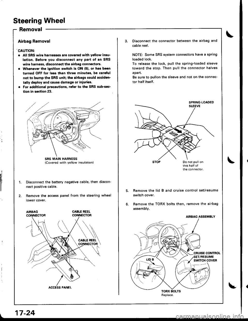
Airbag Removal
'CAUTION:
. All SRS wiro harne33e3 ar€ coverad with yellow insu.
lation. Beforo you di3connect Eny part of En SRS
wiro harn6ss, disconnsct the airbag conncctors.
. Whenaver ths ignition switch is ON {ll}, or ha3 b.cn
turned OFF lor l.3s than thrcc minuto3, be cErs{ul
not to bump th6 SRS unh; the airbags could rcciden-
tally deploy and cause damsgo or iniurias'
. Fo. additional preclution3, rofer to tho SRS sub-soc'
tion in 36ction 23,
Disconnect the battery negative cable, then discon-
nect Dositive cable.
Remove the access panel from the steering wheel
lower cover.
CABLE REEL
L
SRS MAIN HARNESS
17-24
Disconnect the connector between the airbag and
cable reel.
NOTE: Some SRS system connectors have a spring
loaded lock.
To release the lock, pull the spring-loaded sleeve
toward the stop. Then pull the connector halves
apart.
Be sure to pullon the sleeve and not on the connec-
tor half itself.
Remove the lid B and cruise control set/resume
switch cover.
Bemove the TORX bolts then, remove the airbag
assembly.
SPRING.LOADED
AIRBAG ASSEMBLY