Page 769 of 1680

Inspection
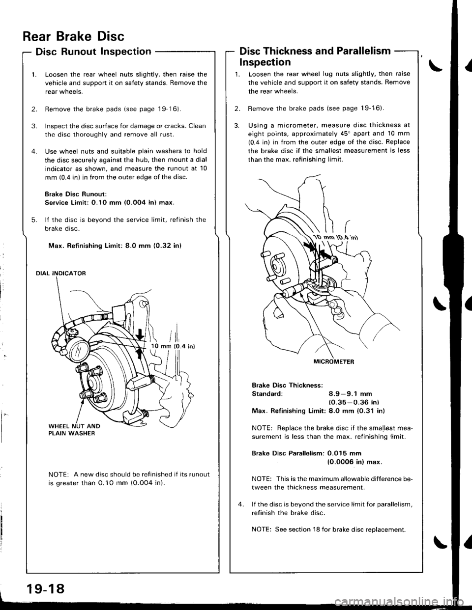
rrii tlmm {0.4 inl10
l.
Rear Brake Disc
Disc Runout Inspection
Loosen the rear wheel nuts slightly, then raise the
vehicle and support it on safety stands. Remove the
rear wneers.
Remove the brake pads (see page 19-16).
Inspect the disc surface for damage or cracks. Clean
the disc thoroughly and remove all rust.
Use wheel nuts and suitable plain washers to hold
the disc securely against the hub, then mount a dial
indicator as shown, and measure the runout at 10
mm (0.4 in) in from the outer edge of the disc.
Brake Disc Runout:
Se.vice Limit: O.1O mm {0.0O4 in) max.
ll the disc is beyond the service limit, refinish the
brake disc.
Max. Refinishing Limit: 8.0 mm (0.32 in)
DIAL INDICATOR
NOTEi A new disc should be refinished if its runout
is greater than 0.'10 mm (O.O04 in).
Disc Thickness and Parallelism
Loosen the rear wheel lug nuts slightly, then raise
the vehicle and support it on safety stands. Remove
the rear wheels.
Remove the brake pads (see page 19-16).
Using a micrometer, measure disc thickness at
eight points, approximately 45" apart and 10 mm
(0.4 in) in from the outer edge of the disc. Replace
the brake disc if the smallest measurement is less
than the max. retinishing limit.
Bfake Disc Thickness:
Standard: 8.9 - 9.1 mm
(0.35-0.36 in)
Max. Refinishinq Limit:8.O mm (0.31 in)
NOTE: Replace the brake disc it the smaLlest mea-
surement is less than the max. retinishing limit.
Brake Disc Parallelism: O.O15 mm
(O.00O6 in) max.
NOTE: This is the maximum allowable difference be-
tween the thickness measurement.
lf the disc is bevond the service limit for parallelism,
refinish the brake disc.
NOTE: See section 18 for brake disc replacement.
\S rnrn .\'rn)
19-18
Page 791 of 1680

Troubleshooting
ABS lndicator Does Not Come On
\
GAUGE ASSEMBLY 5P CONNECTON
Wire sid€ of female terrninals
Th. A8S indicator light does notcoma on whon ignition swhch islum6d ON llll.
check the METER {7.5 A) tuse inthe under-dash tuse/relay box.and reinstallthe fuse it it is OK.
Replacsthefuse.nd recheck.
Ch.ck th. ABS control unit:Disconnect the ABS control unit12P connector.
Chock for loola ABS contlol unitconnector!. ll noco$rry !ubsti-tut6 a known-good ABS controlunit and r6chock.
Check tor .n opon in the lcl cir-cuit:1. Disconnect the gauge assem-bly 5P connector.2. Turn the ignition switch ON (ll).
3. Measure the voltage botweenthe gaugo assombly 5P con-nector terminal No. 'l andbody ground.. Repair open in tho wir. betwoanthe METER 17.5 A) tuso.ndgaugo a$embly.. R.pl.co tho under-dash furo/.elay box. lopen circuit insidethe box.l
check the A8s indicator bulb inthe gauge assembly.
R6olace tho ABS indicrtor bulb.
Ch.ck tor ! short to body groundin th6 WALP circuit:Check tor continuity b€tween thegauge assembly 5P connectorterminal No. 4 and body ground.
R€pair short to body ground in thowira b€tw6on tho gaug6 asscmblysnd the A&S control unit.
lTo page'19-41)
WALP {BLU/REO}
Page 792 of 1680
Chsck tor an opon in th6 indicr-tor light GND circuh:'1. Turn the ignition switch OFF.2. Connect the gaugs assembly5P connector.3. Connect the gauge assembly5P conneclor tgrminal No. 3 tobody ground with a jumper
4. Turn the ignition s:witch ON (ll).
. R€pair opan in tho wiro botw.anthe gaug. r$.mbly .nd bodyground.. Ropsir poor ground lcil()i l.
Does the ABS indicatorcome on?
Roplac6 th6 printod circuit bo.rdin tho gaug6 assembly.
GAUGE ASSEMBLY 5P CONNECIOR
F---.q-l1 l/l3l415l-J6ii-6r-xr
JUMPER IwrRE I
Wre sid6 of lemale terminals
19-41
Page 793 of 1680

Troubleshooting
ABS Indicator Does Not Go Off
JUMPERWIRE
ABS OO TNOL UMT 22P OO'{NECTOR
Wire side of temalo terminalg
A8S COI{TROL Ut{lT 12P OO I{ECTOR
JUMPEFWIRE
Wire side of femal€ terminala
|G2 IALK/YELI
- The ABS indicltor light doosnot go ofl aftor lhe engine is3tartod.- With the SCS sorvico connoctor connoct d l.oe page 19371,no DTC b indbat€d.
ChECK thE REAF DEFROSTERRELAY (7.5 A) fuse in the under-dash fuse/relay box, and reinstallthe fuso if it is OK.
Roplaco tho tusa and rocheck.
Chock for an opcn GND circuit:1. Connect the ABS control unit22P connector terminal No. 1to body ground with a jumper
2. Turn the ignition switch ON (ll).
. Ropair opon in tha wiro botwocntho ABS control unit and bodyground.' Ropair poo. ground {G701 }.
Check for an open in thc lG2 ci.-cuit:Measure the voltage botween theABS control unit 22P connectorterminal No. 11 and body ground.
Roprir opon in thc wira bdtwoentho REAR OEFROSTER RELAY17.5 Al fu$ end th. ABS controlunit.
ls th6re battery voltage?
Check the ABS contJol unit:Connect the ABS control unit 12Pconnector terminal No. 1 to bodyground with a jumper wire.
Chock for looao ABS control unhconncctoas, It nacas3aly, sub3ti-tuto a known-good ABS controlunit and r.check.
(To page 19-43)
19-42
Page 858 of 1680

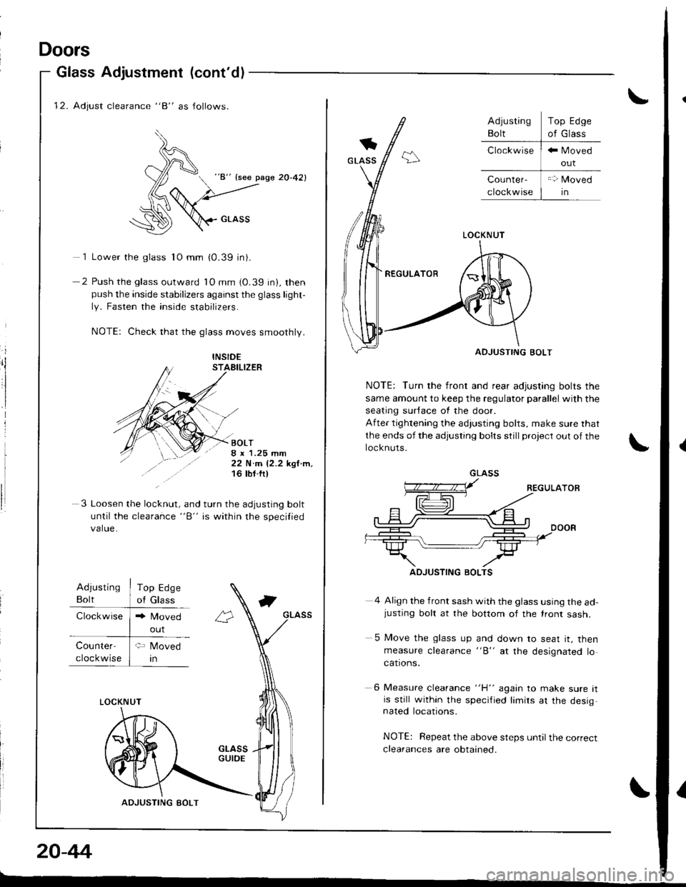
12. Adjust clearance "8" as follows.
)^
d "8" {see pase 20-42}
(6
:\D \crnss
1 Lower the glass 1O mm (0.39 in).
2 Push the glass outward lO mm (0.39 in), thenpush the inside stabilizers against the glass light-
ly. Fasten the inside stabilizers.
NOTE: Check that the glass moves smoothly.
i
ilINSID€STAEILIZER
BOLT8 x 1.25 mm22 N.m 12.2 kgl.m,16 tbt ftl
3 Loosen the lo"knrt, "nd turn the adjusting bolt
until the clearance "B" is within the specilied
value.
Adiusting
Bolt
Clockwise
Top Edge
of Glass
Counter-
cloc kwise
LOCKNUT
ADJUSTING BOLT
20-44
Doors
Glass Adjustment (cont'd)
out
\
LOCKNUT
REGULATOR
ADJUSTING BOLT
NOTE: Turn the front and rear adjusting bolts the
same amount to keep the regulator parallel with the
seating sur{ace ot the door.
After tightening the adjusting bolts, make sure that
the ends of the adjusting bolts still project out of the
locknuts.
4 Align the front sash with the glass using the ad-justing bolt at the bottom of the lront sash.
5 Move the glass up and down to seat it, thenmeasure clearance "B" at the designated locations.
6 Measure clearance "H" again to make sure itis still within the specified limirs at the desig,nated locations.
NOTE: Repeat the above steps until the correct
clearances are obtained.
Top Edge
of Glass
GLASS
ADJUSTING BOLTS
I
Page 860 of 1680
Doors
Glass Adjustment (cont'dl
'14. Adiust clearance "B" as Jollows.
"8" lsee page 20-421
- 1 Lower the glass 1O mm (0.39 in).
2 Push the glass outward 10 mm 10.39 in), thenpush the inside stabilizers against the glass light-ly. Fasten the inside stabrIzers.
NOTEr Check that rhe glass moves smoothly.
BOLT8 x 1.25 mm22 N.m (2.2 kgf.m,'t6 tbt.fr)
20-46
-
-.\
CENTER [L\LGLAss lilffiGUTDE I li$lliun
\fiJrtrlAl-,/"
.-3 Loosen the upper locknut on the center glassguide, and turn the adjusting bolt until clearance"B" is within the specified value.
ADJUSTING BOLT
LOCKNUT
22 N.m 12.2 kgt tn,16 lb{.ttl
*
GLASS
NOTE: Do not adjust the lower adjusting boltson the center glass guide.
-4 Move the glass up and down to seat jt, then
measure clearance "B" at the designatedlocations.
- 5 Measure clearance "H" again to make sure itis still within the specified limits ar the desig,nated locations.
NOTE: Repeat the above steps until the correctclearances are obtained.
Top Edge
of Glass
Page 862 of 1680

Doors
Position Adjustment
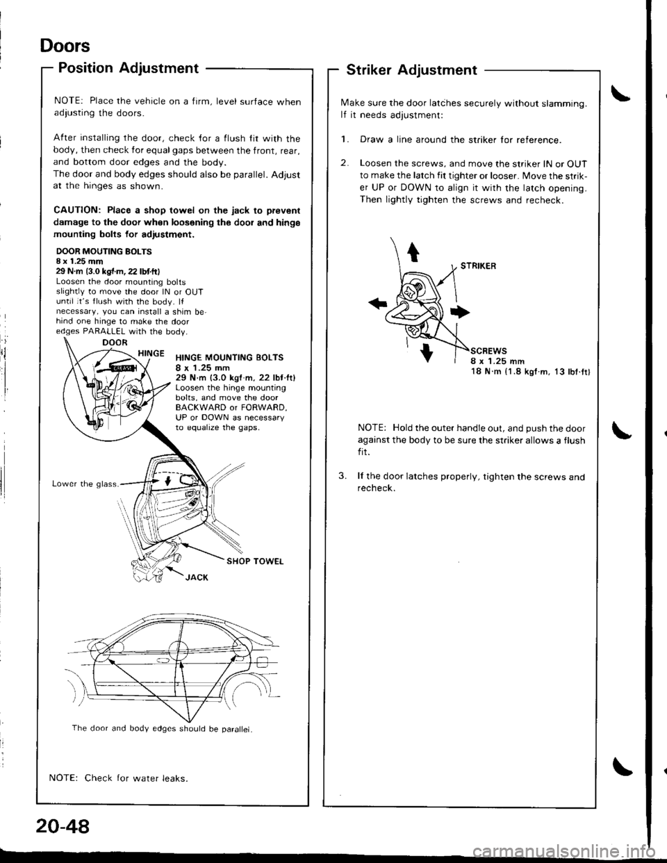
NOTE: Place the vehicle on a firm, level surface whenadiusting the doors.
After installing rhe door, check {or a flush lir with the
body, then check for equalgaps between the front, rear,
and bottom door edges and the body.
The door and body edges should also be parallel. Adjustat the hinges as shown.
CAUTION: Place a shop towel on the jack to prevenl
damage to the doof when loosening the dool and hinge
mounting bolts for adiustmont.
DOOR MOUTING BOLTSI x 1.25 mm29 N.m (3.0 kgt.m,22 lbtft)Loosen the door mounting boltsslightly to move the door lN or OUTuntil it's flush with the body. lfnecessary, you can install a shim be-hind one hinge to make the dooredges PARALLEL with the bodV.
HINGEHINGE MOUNTING BOLTS8 x 1.25 mm29 N.m (3.0 kgf m, 22 lbt.lt)Loosen the hinge mountingbolts, and move the doorBACKWARD or FORWARD,UP or DOWN as necessaryto equalrze tne gaps,
Lower the g lass.
SHOP TOWEL
Check for water leaks.
.iDOOR
N,4ake sure the door latihes securely without slamming.
lf it needs adjustment:
1. Draw a line around the striker lor reference.
2. Loosen the screws, and move the striker lN or OUT
to make the latch fit tighter or looser. Move the strik-
er UP or DOWN to align it with the latch opening.
Then lightly tighten the screws and recheck.
scBEws8 x '1.25 mm18 N.m {1.8 kgf.m. 13 lbf.tt}
NOTE: Hold the outer handle out, and push the door
against the body to be sure the striker allows a flush
fit.
ll the door latches properly, tighten the screws andrecheck.
3.
20-48
The door and body edges should be parallel.
-"
Page 872 of 1680

Windshield
Installation (cont'dl
With a sponge, apply a light coat of glass primer
around the edge of the windshield as shown, then
lightly wipe it o{f with gauze or cheesecloth.
NOTE:a Do not apply body primer to the windshield, and
do not get body and glass primer sponges mixed
up.
a Never touch the primed surtaces with your hands.
lf you do, the adhesive may not bond to the wind
shield properly, causing a leak after the windshield
is installed.
a Keep water, dust, and abrasive materials away
from the primed sur{ace.
V///t t applv slass primer her6.
UPPER RUBBER UPPERDAM MOLDING
WINDSIIIELD
UPPER MOLOING
n------kBB''i+,
KKKxxl DAM
20-58
1O. With a sponge, apply a light coat oI body primer to
the original adhesive remaining around the wind-
shield opening llange. Let the body primer dry tor
at least 10 minutes.
NOTE:
a Do not apply glass primer to the body, and be
carelul not to mix up glass and body primer
sponges.
o Never touch the primed surfaces with your hands.
a Mask olf the dashboard be{ore painting the
flange.
/////,, epptv body p.imer here.
16 mm{0.63 inl
5 mm {0.19 in)
6 mm {0.23 inl'16 mm{0.63 in}
5mm(O.'19 inl
16 mm10.63 in)
1'1. Thoroughly mixthe adhesive and hardener together
on a glass or metal plate with a putty knife.
NOTE:
a Clean the plate with a sponge and alcohol before
mlxlng.
a Follow the instructions that come with the
adhesive.
12. Before filling a cartridge, cut the end of the nozzle
as shown.
10 mm {O.39 in}