1998 ACURA INTEGRA key battery
[x] Cancel search: key batteryPage 1128 of 1680
lgnition Switch
Electrical Switch Replacement
SRS comoonents are located in this ar8a. Review thE
SRS component locations, precautions, and procedures
in the SRS section (23) before performing repairs or ser-
vice.
NOTE: The original radio has a coded thett protection
circuit, Be sure to get the customer's code number before- disconnecting the battery.- removing th6 No. 47 (7.5 A) tuse from the under-hood
tuse/relav box,- removing the radio.
After service, reconnect oower to the radio and turn it
on. When the word "CODE" is displayed, enter the cus-
tomer's s-digit code to restore radio operation.
1. Disconnect the negative cable from the battery.
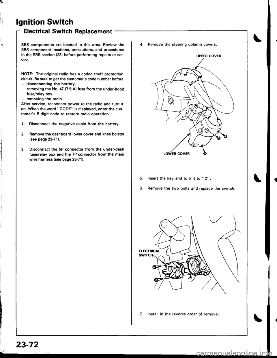
4. Remove the steering column covers.
Romovs ths dashboard lower cover 8nd knes bolster(se6 p8g6 23-71).
Disconnsct th6 5P connector from th6 under-dash
fuse/rel8y box 6nd th€ 7P conn€ctor from the main
wire harne$ (s6e page 23-711.
5.Insert the key and turn it to "O".
Remove the two bolts and replace the switch6.
UPPER COVER
7. Install in the reverse order of removal.
23-72
Page 1129 of 1680
;
Steering Lock Replacement
SRS components are located in this area. Review the
SRS component locations, precautions, and procedures
in the SRS section (23) before performing repairs or ser-
vice.
NOTE: The original radio has a coded theft protection
circuit. Be sure to get the customer's code number before- disconnecting the battery.- removing the No. 47 (7.5 A) fuse trom the under-hood
fuse/relav box.- removing the radio.
After service, reconnect power to the radio and turn it
on. When the word "CODE" is displayed. enter the cus-
tomer's 5-digit code to restore radio operation.
1. Disconnect the negative cable from the battery.
2. Remove ths dsshboard lower cover and knee bolster(s6o p8ge 23-72).
3, Disconnect the 5P connector from the under-dash
fuse/relay box and the 7P connsctor from th€ main
wire harness (see page 23-72l.,
4. Remove the steering column covars (see page
23-721.
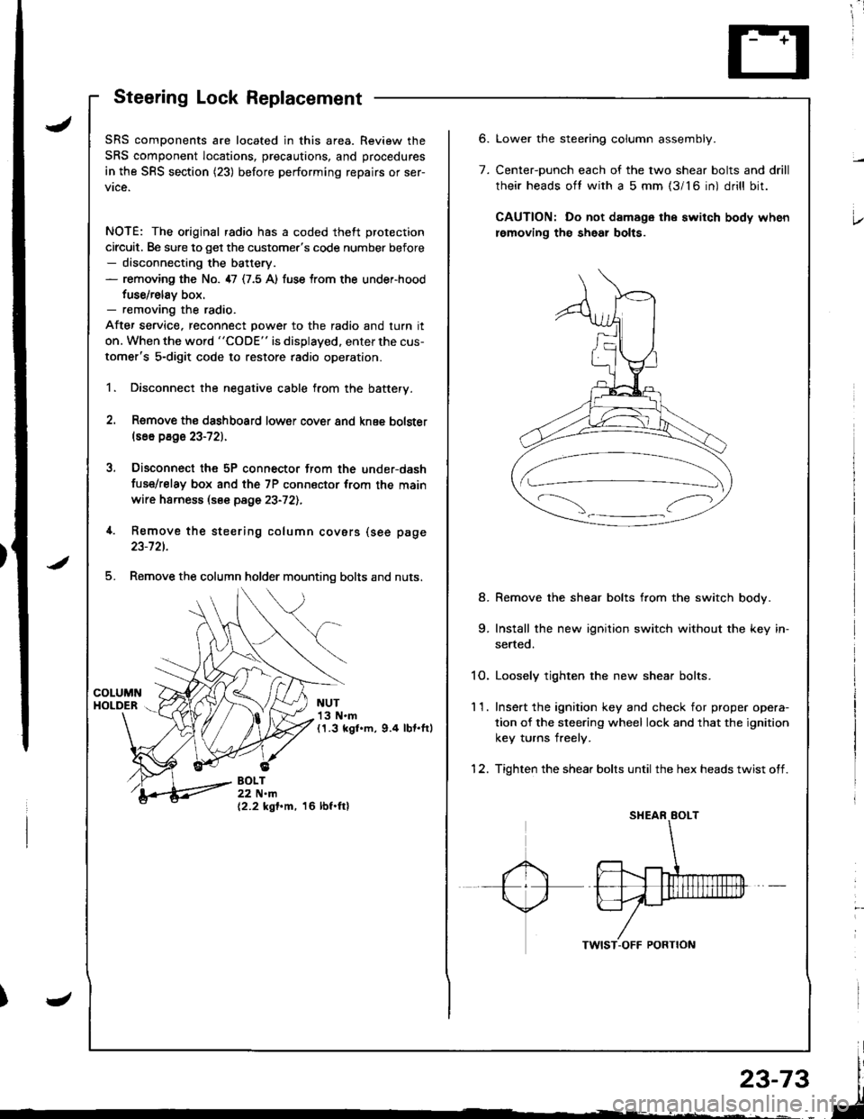
5. Remove the column holder mounting bolts and nuts.
NUT13 N.m(1.3 kgl.m, 9.4 lbt.ftl
BOLT22 N.m(2.2 kgf.m, 16 lbf.ftl
6.
7.
Lower the stee.ing column assembly.
Center-ounch each of the two shear bolts and drill
their heads oft with a 5 mm {3/16 in) drill bit.
CAUTION: Do not damage the switch body when
lemoving th€ sheal bolts.
Remove the shear bolts from the switch body.
Install the new ignition switch without the key in-
serted.
1O. Loosely tighten the new shear bolts.
11. Ins€rt the ignition key and check for proper opera-
tion of the sleering wheel lock and that the ignition
key turns freely.
12. Tighten the shear bolts until the hex heads twist off.
8.
Page 1134 of 1680
Starting System
Starter Test (cont'dl
Check Cranking rpmr
Engine speed during cranking should be above 1OO rpm.
lJ speed is too low, check for:
a Loose batlery or starter terminals
a Excessively worn starter brushes
a Open circuit in commutator segments
a Dirty or damaged helical spline or drive gear
a Defective drive gear overrunning clutch
Check Starter Disengagement:
Press the clutch pedal all the way in (M/T), turn rhe igni
tion switch to "lll" and release to "11".
The starter drive gear should disengage from the flywheel
or torque converter ring gear when you release the key.
It the drive gear hangs up on the flywheel or torque con-
verter ring gear, check for:
a Solenoid plunger and switch mallunction
a Dirty drive gear assembly or damaged overrunning
clutch
5. Check for an open in the BLK/WHT wire circuit be
tween the starter and ignition switch, and con-
necrors,
6. Check the ignition switch (see page 23-71).
7. On cars with automatic transmission, check the A/Tgear position switch (neutral position switch) and
connector. On cars with manualtransmission, check
the starter cut relay, clutch interlock switch, and
connectors.
NOTE: Check the No. 42 (40 A) fuse in the under,hoodfuse/relay box for the starter cut relay.
Check Jor Wear and Damage:
The starter should crank the engine smoothly and stead,ily. lf the starter engages, but cranks the engine errati
cally, remove it. Inspect the starter, drive gear, andllywheel or torque converter ring gear lor damage.
a Check the drive gear overrunning clutch for binding
or slipping when the armature is rotated with the drivegear held. Replace the gears i{ damaged.
Check CJanking Voltage and Current Draw:
Cranking voltage should be no less than 8.O volts.
Current draw should be no more than * amperes.* 1.2 kW: 27O A
1 .4 kW: 360 A
It cranking voltage is too low, or current draw too high,check for:
a Dead or low charged batterya Open circuit in starter armature commutator segmentsa Starter armalure dragging
a Shorted armature windinga Excessive drag in engine
Page 1205 of 1680
){r/
Control Unit Input Test
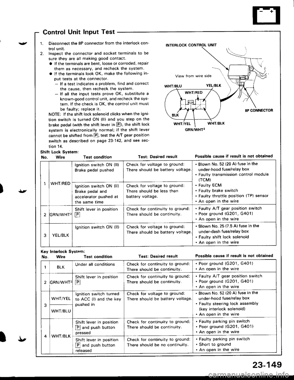
1. Disconnect the 8P connector from the interlock con-
trol unit.
2. lnspect the connector and socket terminals to be
sure they are all making good contact.
a It the terminals are bent, loose or corroded, repair
them as necessary, and recheck the system.
a lf the terminals look OK, make the following in-
put tests at the connector.- lf a test indicates a problem, tind and correct
the cause, then recheck the system.- lf all the input tests prove OK, substitute a
known-good control unit, and recheck the sys-
tem. lf the check is OK, the control unit must
be faulty; replace it.
NOTE: lf the shift lock solenoid clicks when the igni-
tion switch is turned ON (ll) and you step on the
brske Dedal (with the shift lever in E). the shift lock
system is electronically normal; if the shift lever
cannot be shifted from fl, test the 46 gear position
switch as described on page 23-142, and see sec-
tion 14.
Shift Lock System:
No. Wire Test condition
No. WireTest condition
Test: Desired resultPossible causs it result is not obtained
Test: Dcsired lesultPossible cause it result is not obtainsd
INTERLOCK CONTROL UNIT
GRN/wHT2
1WHT/RED
lgnition switch ON (ll)
Brake pedal pushed
Check for voltage to ground:
There should be battery voltage
Blown No. 52 {20 A) fuse in the
under-hood fuse/relaY box
Faulty transmission control module
(TCM)
Faulty ECM
Faulty brake switch
Faulty throttle position (TP) sensor
An open in the wire
lgnition switch ON (ll)
Brake pedal and
accelerator pushed at
the same me
Check for voltage to ground:
There should be less than
battery voltage.
tGRN/WHT'
Shift lever in position
E
Check tor continuity to ground:
There should be continuity.
Faulty A/T gear position switch
Poor ground {G20'1 , G401)
An open in the wire
3YEL/BLK
lgnition switch ON (ll)Check for voltage to ground:
There should be battery voltage
Blown No. 25 (7.5 A) fuse in the
under-dash fuse/relay box
Faulty shift lock solenoid
An open in the wire
Key Int€rlock Systcm:
BLKUnder all conditionsCheck lor continuity to ground:
There should be continuitY.
. Poor ground (G201, G401). An open in the wire
GRNiWHT'
Shift lever in position
E
Check for continuity to ground:
There should be continuity.
Faulty A/T gear position switch
Poor ground {G2O1, G401 }
An open in the wire
3
WHT/YELlgnition switch turned
to ACC (l) and the key
pushed in
Check tor voltage to ground:
There should be battery voltage.
Blown No. 52 (20 A) fuse in the
under-hood fuse/relaY box
Faulty steering lock assemblY
(key interlock solenoidl
An open in the wireWHT/BLU
4WHT/BLK
Shift lever in position
E and push button
pressed
Check for continuity to ground:
There should be continuity.
Faulty pafking pin switch
Poor ground (G2O1, G4O 1)
An open in the wire
Shift lever in position
E and push button
reteaseo
Check for continuity to ground:
There should be no continuity.
Faulty parking pin switch
Short to ground
An open in the wire
I'
23-149
Page 1212 of 1680
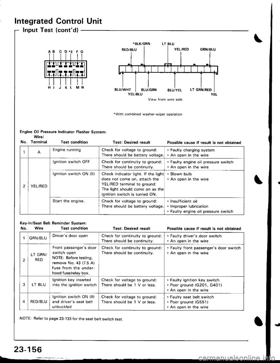
Integrated Control Unit
lnput Test (cont'd)
YEL/BLU
View from wire side
'With combined washer-wiper operation
Engine Oil Pressure Indicator Flasher System:
Wire/
No. TerminalTest condition
Key-in/Seat Belt Reminder System:
No. WileTest condition
Testi Desired result
Test: Desired result
Possible cause if result is not obtainsd
Possible cause if fesult is not obtained
*BLK/GRN
1Engine runningCheck for voltage to ground:
There should be battery voltage.
. Faulty charging system. An open in the wire
2YEL/RED
lgnition switch OFFCheck for continuity to ground:
There should be continuity.
. Faulty engine oil pressure switch. An open in the wire
lgnition switch ON (ll)Check indicator light. It the light
does not come on, attach the
YEL/RED terminal to groundl
The light should come on as the
ignition switch is turned ON.
. Blown bulb. An open in the wire
Start the engine.Check tor voltage to ground:
There should be battery voltage
lnsufticient oil
lmproper lubrication
Faulty engine oil pressure switch
1GRN/BLUDriver's door openCheck for continuity to ground:
There should be continuity.
. Faulty driver's door switch. An open in the wire
2
LT GRN/
RED
Front passenger's door
swrlcn open
NOTE: Before testing,
remove No. 43 {7.5 A)
fuse from the under-
hood fuse/relay box.
Check for continuity to ground:
There should be continuity.
. Faulty front passenger's door switch'An open in the wire
3LT BLU
lgnition key inserted
into the ignition switch
Check for voltage to ground:
There should be 1 V or less.
Faulty ignition key switch
Poor ground (G2O1, G401 l
An open in the wire
4RED/BLU
lgnition switch ON (lll
and driver's seat belt
unbuckled
Check for voltage to ground:
There should be 1 V or less.
Faulty seat belt switch
Poor ground (G551l
An open in the wire
NOTE: Refer to page 23-133 for the seat belt switch test.
Page 1299 of 1680
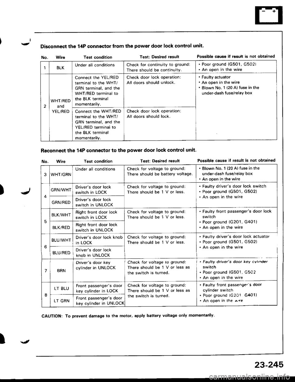
Disconnect the 14P connector from the power door lock control unit'
)
No. WileTest conditionTest: Dgsired resultPossible causo if rosult is not obtained
Reconnect the 14P conneetor to the power door lock control unit'
No. wireTest conditionTest: Desired resultPossible cause il result is not obtained
I
1BLKUnder all conditionsCheck tor continuity to ground:
There should be continuity.
. Poor ground (G50'1, G502). An open in the wire
2
WHTi RED
ano
YEL/RED
connect the YEL/RED
terminal to the WHT/
GBN terminal, and the
WHT/RED terminal to
the BLK terminal
momentarily.
Check door lock operation:
All doors should unlock.
Faulty actuator
An open in the wire
Blown No. 1 {20 A} fuse in the
under-dash Juse/relay box
Connect the WHT/RED
terminal to the WHT/
GRN terminal, and the
YEL/RED terminal to
the BLK terminal
momentanly.
Check door lock operation:
All doors should lock.
3WHT/GRN
Under all conditionsCheck for voltage to ground:
There should be battery voltage.
. Blown No. 1 (20 A) fuse in the
under-dash fuse/relay box. An open in the wire
GRN/WHTDriver's door lock
switch in LOCK
Check lor voltage to ground:
There should be 1 V or less.
Faulty driver's door lock switch
Poor ground (G501, G502)
An open in the wire
GRN/REDDriver's door lock
switch in UNLOCK
5
BLK/WHTRight front door lock
switch in LOCK
Check for voltage to ground:
There should be 1 V or less.
Faulty front passenger's door lock
switch
Poor ground (G201 , G401)
An open in the wireBLKi REDRight front door lock
switch in UNLOCK
BLU/WHTDriver's door lock knob
in LOCK
Check for voltage to ground:
There should be 1 V or less.
. Faulty driver's door lock actuator. Poor ground (G501, G502). An open in the wire
BLU/REDDriver's door lock
knob in UNLOCK
7BRN
Oriver's doo. key
cylinder in UNLOCK
Check for voltage to ground:
There should be 1 V or less as
the switch is turned.
. Faulty driver's door key cvtrrder
switch. Poor ground (G501, G502. An open in the wire
8
LT BLUFront passenger's door
key cylinder in LOCK
Check for voltage to ground:
There should be 1 V or less as
the switch is turned.
. Faulty front passengef's door
cylinder switch. poor ground lG20r G4Ol). An open in the *reLT GRNFront passenger's door
key cylinder in UNLOCK
\J
CAUTION: To prevent damage to the motol, apply battery voltage only momentarily
23-245
Page 1304 of 1680
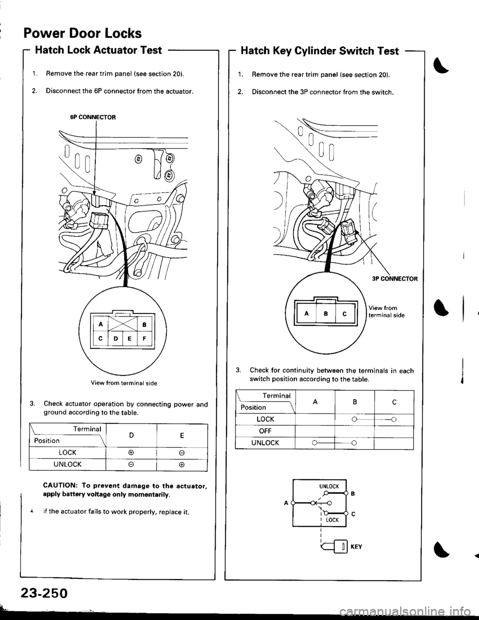
Power Door Locks
Hatch Lock Actuator Test
Remove the rear t.im panel (see section 20).
Disconnect the 6P connector from the actuator.
1.1.
2.
Hatch Key Cylinder Switch Test
Remove the rear trim panel (see section 20).
Disconnect the 3P connector from the switch.
3. Check for continuitv between the terminals in each
switch position according to the table.
6P CONNECTOR
3. Check actuator operation by connecting power andground according to the table.
CAUTION: To prev€nt damage to the actuator,
apply battery voltage only momeniarily.
1 lf the actuator fails to work properly, replace it,
23-250
Terminal
ilil;---tBc
LOCKoo
UNLOCKo
Terminal
ilil;-]E
LOCK@o
UNLOCKoo
UNLOCK
.-,4
I LOCK
| !J KEY
Page 1339 of 1680
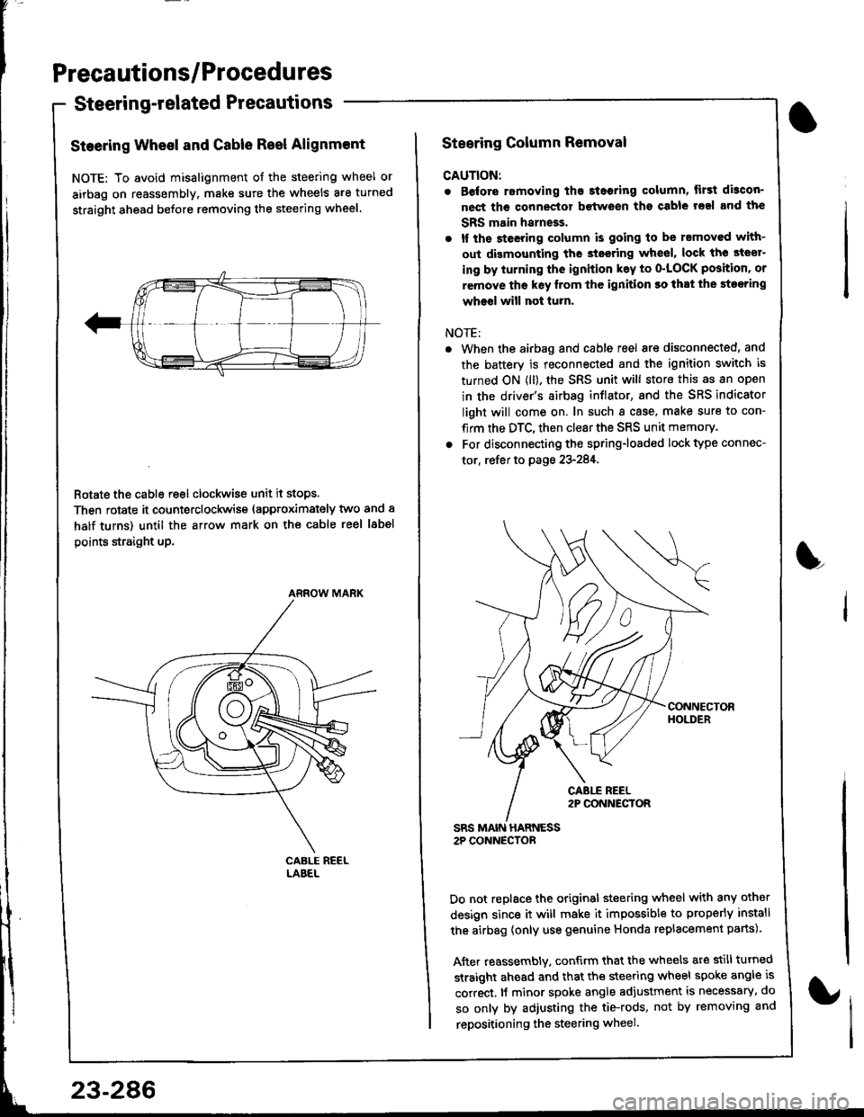
Precautions/Procedures
Steering-related Precautions
Steering Wheel and Gable Reel Alignment
NOTE: To avoid misalignment of the steering wheel or
airbag on reassembly. make sure the wheels are turned
straight ahead before removing the steering wheel.
Rotate the cable reel clockwise unit it stops.
Then rotate it counterclockwise (approximately two and a
half turns) until the arrow mark on the cable reel label
points straight up.
ARROW MARK
23-286
Steering Column Removal
CAUTION:
. Before romoving the steoring column, lirst di3con-
nect ths connector bctwoen tho csble rsal and the
SBS main harneEs.
. lf the steeting column is going to be rsmoved with-
out dismounting the steering wheel, lock the steer-
ing by iurning the ignition k6y to o'LOCK position' or
remove tho key lrom thc ignition ro that the steering
wheel will not turn.
NOTE:
When the airbag and cable reel are disconnected, and
the battery is reconnected and the ignition switch is
turned ON (ll), the SRS unit will store this as an open
in the driver's airbag inflator, and the SRS indicator
light will come on. In such a case, make sure to con-
firm the DTC, then clear the SRS unit memory.
For disconnecting the spring-loaded lock type connec-
tor, refer to page 23-284,
SRS MAIN HARNESS2P CONNECTOR
Do not replace the original steering wheel with any other
design since it will make it impossible to properly install
the airbag {only use genuine Honda replacement parts).
After reassembly. confirm that the wheels are still turned
straight ahead and that the steering wheel spoke angle is
correct, lf minor spoke angle adjustment is necessary, do
so only by adjusting the tie-rods, not by removing and
repositioning the steering wheel.
L