Page 1310 of 1807
(3)
(1) EM-58
- ENGINE MECHANICAL (2JZ-GTE)ENGINE UNIT
1163 Author�: Date�:
1997 SUPRA (RM502U)
REMOVAL
1. REMOVE HOOD
2. REMOVE RADIATOR ASSEMBLY
(See page CO-22)
3. DRAIN ENGIN")
EM0AV-02
P11544
(2)(3)
(1) EM-58
- ENGINE MECHANICAL (2JZ-GTE)ENGINE UNIT
1163 Author�: Date�:
1997 SUPRA (RM502U)
REMOVAL
1. REMOVE HOOD
2. REMOVE RADIATOR ASSEMBLY
(See page CO-22)
3. DRAIN ENGINE OIL
4. DRAIN FUEL FROM FUEL TANK
5. REMOVE NO.1 AIR HOSE
6. DISCONNECT CONTROL CABLES FROM
THROTTLE BODY
Disconnect these cables:
�Accelerator cable
�Cruise control actuator cable
7. REMOVE AIR CLEANER AND MAF METER
ASSEMBLY
(a) Remove the 3 bolts.
(b) Loosen the hose clamp, disconnect the air hose from the
intake air connector.
(c) Disconnect the MAF meter wire from the clamp on the air
cleaner case.
(d) Disconnect the MAF meter connector, and remove the air
cleaner and MAF meter assembly.
8. M/T:
REMOVE DRIVE BELT TENSIONER DAMPER
(See page EM-15)
9. REMOVE DRIVE BELT, FAN, FLUID COUPLING
ASSEMBLY AND WATER PUMP PULLEY
(See page CO-7)
10. REMOVE CHARCOAL CANISTER
11. DISCONNECT HEATER WATER HOSES
12. DISCONNECT BRAKE BOOSTER VACUUM HOSE
13. DISCONNECT EVAP HOSE
14. DISCONNECT WIRES AND CONNECTORS
(a) Disconnect these connectors:
(1) Solenoid resistor connector
(2) Noise filter connector
(3) Igniter connectors
(b) Disconnect the engine wire from the PS oil reservoir pro-
tector
.
Page 1321 of 1807
ENGINE UNIT
EM-69
1174 Author�: Date�:
1997 SUPRA (RM502U)
24. INSTALL PS PUMP
(a) Install the pump bracket with the 3 bolts.
Torque:
A 58 N´m (590 kgf´")
Z09735
B B
A
- ENGINE MECHANICAL (2JZ-GTE)ENGINE UNIT
EM-69
1174 Author�: Date�:
1997 SUPRA (RM502U)
24. INSTALL PS PUMP
(a) Install the pump bracket with the 3 bolts.
Torque:
A 58 N´m (590 kgf´cm, 43 ft´lbf)
B 39 N´m (400 kgf´cm, 29 ft´lbf)
(b) Install the vane pump with the 2 bolts.
Torque: 58 N´m (590 kgf´cm, 43 ft´lbf)
(c) Connect these hoses:
�PS air hose to throttle body
�PS air hose to air intake chamber
25. CONNECT FUEL HOSES
(a) Connect the fuel return hose to the fuel return pipe.
(b) Install the fuel return hose to the clamp of the dipstick
guide.
(c) Install the fuel inlet hose with 2 new gaskets and the union
bolt.
Torque: 29 N´m (300 kgf´cm, 22 ft´lbf)
26. CONNECT WIRES AND CONNECTORS
27. CONNECT EVAP HOSE
28. CONNECT BRAKE BOOSTER VACUUM HOSE
29. CONNECT HEATER WATER HOSES
30. INSTALL CHARCOAL CANISTER
31. INSTALL WATER PUMP PULLEY, FAN, FLUID
COUPLING ASSEMBLY AND DRIVE BELT
(See page CO-1 1)
32. M/T:
INSTALL DRIVE BELT TENSIONER DAMPER
(See page EM-21)
33. INSTALL AIR CLEANER AND MAF METER
ASSEMBLY
34. INSTALL NO.1 AIR HOSE
35. CONNECT CONTROL CABLES TO THROTTLE
BODY
36. FILL WITH ENGINE OIL
37. INSTALL RADIATOR ASSEMBLY
(See page CO-28)
38. START ENGINE AND CHECK FOR LEAKS
39. INSTALL HOOD
40. ROAD TEST
Check for abnormal noise, shock slippage, correct shift points
and smooth operation.
41. RECHECK ENGINE COOLANT AND ENGINE OIL
LEVELS
Page 1367 of 1807
TIMING BELT
1129 Author�: Date�:
1997 SUPRA (RM502U)
(c) Remove the 1.5 mm hexagon wrench from the tensioner.
13. CHECK VALVE")
P02587
P02154
P11647
S00259
SST
A
BA EM-24
- ENGINE MECHANICAL (2JZ-GTE)TIMING BELT
1129 Author�: Date�:
1997 SUPRA (RM502U)
(c) Remove the 1.5 mm hexagon wrench from the tensioner.
13. CHECK VALVE TIMING
(a) Slowly turn the crankshaft pulley 2 revolutions from TDC
to TDC.
NOTICE:
Always turn the crankshaft clockwise.
(b) Check that each pulley aligns with the timing marks as
shown in the illustration.
If the marks do not align, remove the timing belt and reinstall it.
14. INSTALL DRIVE BELT TENSIONER
Install the tensioner with the 3 bolts.
Torque: 21 N´m (210 kgf´cm, 15 ft´lbf)
NOTICE:
Be careful not to drop the bolts inside the timing belt cover.
15. INSTALL NO.2 TIMING BELT COVER
16. INSTALL NO.3 TIMING BELT COVER
17. INSTALL PS PUMP
(a) Temporarily install the pump pulley with the nut.
(b) Using SST, tighten the pulley nut.
SST 09960-10010 (09962-01000, 09963-01000)
Torque: 43 N´m (440 kgf´cm, 32 ft´lbf)
18. INSTALL WATER PUMP PULLEY, FAN, FLUID
COUPLING ASSEMBLY AND DRIVE BELT
(See page CO-1 1)
19. M/T:
INSTALL DRIVE BELT TENSIONER DAMPER
Torque: 20 N´m (200 kgf´cm, 14 ft´lbf)
20. INSTALL RADIATOR ASSEMBLY
(See page CO-28)
21. ROAD TEST
Check for abnormal noise, shock, slippage, correct shift points
and smooth operation.
Page 1394 of 1807
EM0AD-02
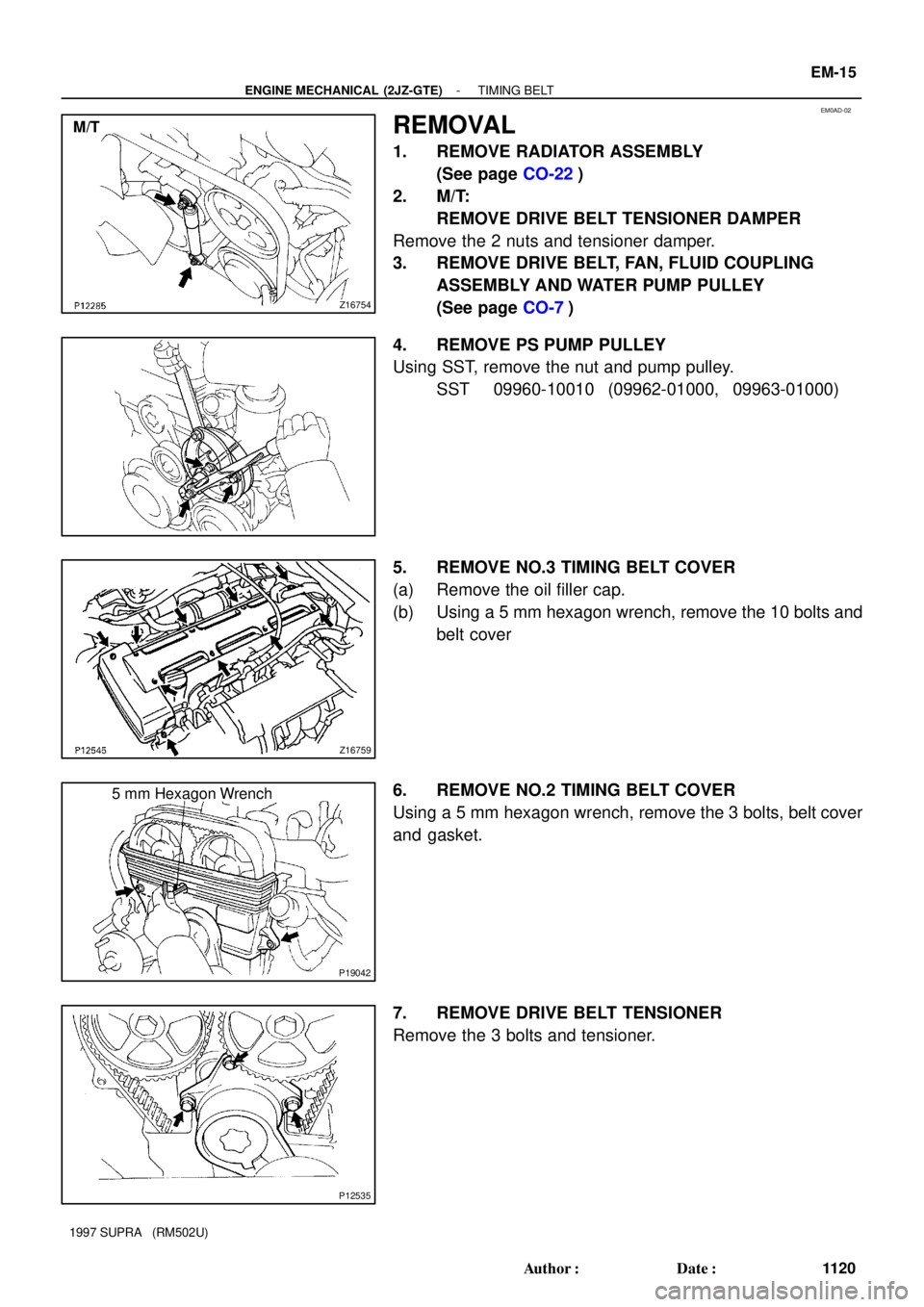
Z16754
M/T
Z16759
P19042
5 mm Hexagon Wrench
P12535
- ENGINE MECHANICAL (2JZ-GTE)TIMING BELT
EM-15
1120 Author�: Date�:
1997 SUPRA (RM502U)
REMOVAL
1. REMOVE RADIATOR ASSEMBLY
(See page CO-22)
2. M/T:
REMOVE DRIVE BELT TENSIONER DAMPER
Remove the 2 nuts and tensioner damper.
3. REMOVE DRIVE BELT, FAN, FLUID COUPLING
ASSEMBLY AND WATER PUMP PULLEY
(See page CO-7)
4. REMOVE PS PUMP PULLEY
Using SST, remove the nut and pump pulley.
SST 09960-10010 (09962-01000, 09963-01000)
5. REMOVE NO.3 TIMING BELT COVER
(a) Remove the oil filler cap.
(b) Using a 5 mm hexagon wrench, remove the 10 bolts and
belt cover
6. REMOVE NO.2 TIMING BELT COVER
Using a 5 mm hexagon wrench, remove the 3 bolts, belt cover
and gasket.
7. REMOVE DRIVE BELT TENSIONER
Remove the 3 bolts and tensioner.
Page 1398 of 1807
(2)
P12534Fuel Return Hose
- ENGINE MECHANICAL (2JZ-GTE)CYLINDER HEAD
EM-29
1134 Author�: Date�:
1997 SUPRA (RM502U)
REMOVAL
1. REMOVE TURBOCHARGER
(See page TC-10)")
EM1DY-01
P11837
P12116
P11642
(1)(2)
P12534Fuel Return Hose
- ENGINE MECHANICAL (2JZ-GTE)CYLINDER HEAD
EM-29
1134 Author�: Date�:
1997 SUPRA (RM502U)
REMOVAL
1. REMOVE TURBOCHARGER
(See page TC-10)
2. REMOVE EXHAUST MANIFOLD
Remove the 12 nuts, exhaust manifold and 2 gaskets.
3. M/T:
REMOVE DRIVE BELT TENSIONER DAMPER
(See page EM-15)
4. REMOVE DRIVE BELT
Loosen the drive belt tension by turning the drive belt tensioner
clockwise, and remove the drive belt.
5. REMOVE WATER OUTLET AND NO.1 WATER
BYPASS PIPE
(a) Disconnect the upper radiator hose from the water outlet.
(b) Disconnect the ECT sensor and sender gauge connec-
tors.
(c) Remove the 2 bolts, water outlet and gasket.
(d) Remove the No.1 water bypass pipe and 2 O-rings.
6. DISCONNECT PS PUMP WITHOUT
DISCONNECTING HOSES
(a) Disconnect these hoses:
(1) PS air hose from throttle body
(2) PS air hose from air intake chamber
(b) Remove the 2 bolts, and disconnect the vane pump from
the pump bracket.
HINT:
Put aside the vane pump, and suspend it.
7. DISCONNECT FUEL RETURN HOSE
Disconnect the fuel return hose from the fuel return pipe. Plug
the hose end.
8. REMOVE AIR INTAKE CHAMBER ASSEMBLY
(See page SF-20)
Page 1420 of 1807

UNDER HOOD
GENERAL MAINTENANCE
1. GENERAL NOTES
�Maintenance items may vary from country to country. Check the owners m")
MA01F-02
MA-4
- MAINTENANCEUNDER HOOD
41 Author�: Date�:
1997 SUPRA (RM502U)
UNDER HOOD
GENERAL MAINTENANCE
1. GENERAL NOTES
�Maintenance items may vary from country to country. Check the owner's manual supplement in which
the maintenance schedule is shown.
�Every service item in the periodic maintenance schedule must be performed.
�Periodic maintenance service must be performed according to whichever interval in the periodic main-
tenance schedule occurs first, the odometer reading (miles) or the time interval (months).
�Maintenance service after the last period should be performed at the same interval as before unless
otherwise noted.
�Failure to do even one item an cause the engine to run poorly and increase exhaust emissions.
2. WINDSHIELD WASHER FLUID
Check that there is sufficient fluid in the tank.
3. ENGINE COOLANT LEVEL
Check that the coolant level is between the ºFULLº and ºLOWº lines on the see-through reservoir.
4. RADIATOR AND HOSES
(a) Check that the front of the radiator is clean and not blocked with leaves, dirt or bugs.
(b) Check the hoses for cracks, kinks, rot or loose connections.
5. BATTERY ELECTROLYTE LEVEL
Check that the electrolyte level of all battery cells is between the upper and lower level lines on the case.
6. BRAKE AND CLUTCH FLUID LEVELS
Check that the brake and clutch fluid levels are near the upper level line on the see-through reservoirs.
7. ENGINE DRIVE BELT
Check drive belt for fraying, cracks, wear or oil contamination.
8. ENGINE OIL LEVEL
Check the level on the dipstick with the engine turned off.
9. POWER STEERING FLUID LEVEL
�Check the level on the dipstick.
�The level should be in the ºHOTº or ºCOLDº range depending on the fluid temperature.
10. AUTOMATIC TRANSMISSION FLUID LEVEL
(a) Park the vehicle on a level surface.
(b) With the engine idling and the parking brake applied, shift the selector into all positions from ºPº to ºLº,
and then shift into ºPº position.
(c) Pull out the dipstick and wipe off the fluid with a clean rag. Re-insert the dipstick and check that the
fluid level is in the HOT range.
(d) Do this check with the fluid at normal driving temperature (70 - 80°C, 158 - 176°F).
HINT:
Wait until the engine cools down (approx. 30 min.) before checking the fluid level after extended driving at
high speeds, in hot weather, in heavy traffic or pulling a trailer.
11. EXHAUST SYSTEM
If any change in the sound of the exhaust or smell of the exhaust fumes is noticed, have the cause located
and corrected.
Page 1743 of 1807
SS0DW-01
- SERVICE SPECIFICATIONSCOOLING
SS-23
180 Author�: Date�:
1997 SUPRA (RM502U)
COOLING
SERVICE DATA
ThermostatValve opening temperature
Valve lift at 95°C (203°F)80 - 84°C (176 - 183°F)
8.5 mm (0.335 in.) or more
Radiator capRelief valve opening pressure STD
Minimum93 - 123 kPa
(0.95 - 1.25 kgf/cm2, 13.5 - 17.8 psi)
78 kPa (0.8 kgf/cm2, 11.4 psi)
Electric
cooling fanRotating amperage2.5 - 4.5 A
Page 1744 of 1807
SS0DX-02
SS-24
- SERVICE SPECIFICATIONSCOOLING
181 Author�: Date�:
1997 SUPRA (RM502U)
TORQUE SPECIFICATION
Part tightenedN´mkgf´cmft´lbf
Engine drain plug x Cylinder block2930022
Fan x Fluid coupling7.47565 in.´lbf
Water pump x Cylinder block2121015
Water pump x No.2 water bypass pipe2121015
Generator x Water pump3738027
Generator x Cylinder block3738027
Water bypass outlet (2JZ-GE) x Cylinder head8.89078 in.´lbf
Water outlet (2JZ-GTE) x Cylinder head2121015
Fluid coupling assembly x Water pump pulley1616512
Water inlet x Water pump2JZ-GE
2JZ-GTE8.8
2190
21078 in.´lbf
15
Upper radiator support x Body1515511
Oil cooler x Radiator lower tank A/T8.38574 in.´lbf
Oil cooler x Oil cooler pipe A/T1515011
Fan motor (2JZ-GTE) x Fan shroud4.95043 in.´lbf
ECT switch (2JZ-GTE) x Radiator7.47565 in.´lbf
Fluid coupling x Water pump1616512