Page 549 of 1807
CO0ZZ-01
P12769
PryClip Pull
Disconnect
P12217
P13162
(2)
(1)
P11646
Plug
(4)(3) CO-22
- COOLINGRADIATOR
1435 Author�: Date�:
1997 SUPRA (RM502U)
REMOVAL
1. REMOVE ENGINE UNDER COVER
HINT:
Start the engine, and check for coolant and A/T fluid leaks.
2. REMOVE BATTERY AND BATTERY TRAY
3. DRAIN ENGINE COOLANT
4. 2JZ-GTE:
REMOVE NO.2 AIR TUBE
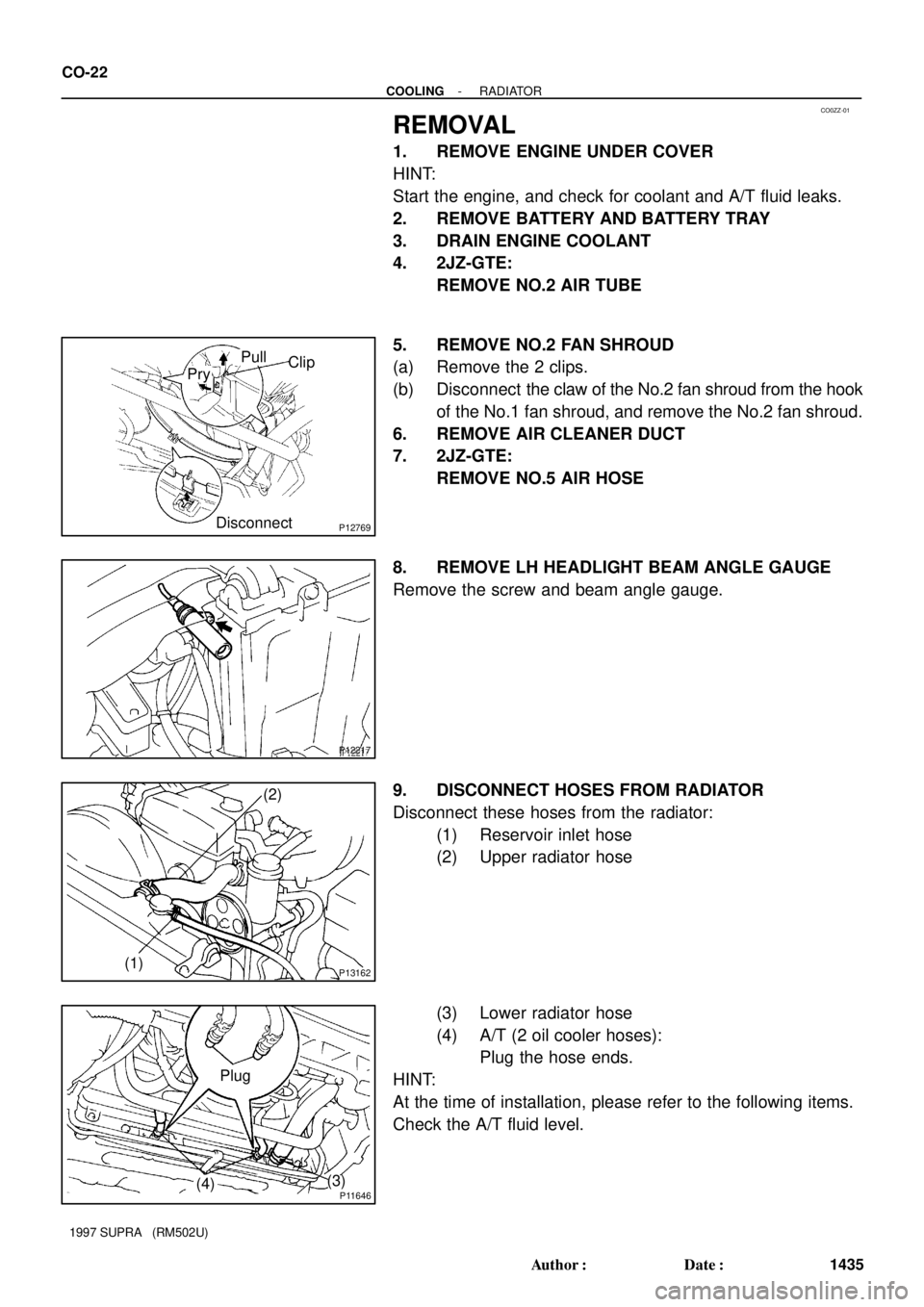
5. REMOVE NO.2 FAN SHROUD
(a) Remove the 2 clips.
(b) Disconnect the claw of the No.2 fan shroud from the hook
of the No.1 fan shroud, and remove the No.2 fan shroud.
6. REMOVE AIR CLEANER DUCT
7. 2JZ-GTE:
REMOVE NO.5 AIR HOSE
8. REMOVE LH HEADLIGHT BEAM ANGLE GAUGE
Remove the screw and beam angle gauge.
9. DISCONNECT HOSES FROM RADIATOR
Disconnect these hoses from the radiator:
(1) Reservoir inlet hose
(2) Upper radiator hose
(3) Lower radiator hose
(4) A/T (2 oil cooler hoses):
Plug the hose ends.
HINT:
At the time of installation, please refer to the following items.
Check the A/T fluid level.
Page 550 of 1807

Z16741
Drain
Hose
ECT Switch (2JZ-GTE)
S05171
- COOLINGRADIATOR
CO-23
1436 Author�: Date�:
1997 SUPRA (RM502U)
10. REMOVE RADIATOR ASSEMBLY
(a) 2JZ-GTE:
Disconnect the ECT switch (for ele")
P11908
(A)
Z16741
Drain
Hose
ECT Switch (2JZ-GTE)
S05171
- COOLINGRADIATOR
CO-23
1436 Author�: Date�:
1997 SUPRA (RM502U)
10. REMOVE RADIATOR ASSEMBLY
(a) 2JZ-GTE:
Disconnect the ECT switch (for electric cooling fan con-
nector) and wire harness.
(b) 2JZ-GTE:
Disconnect the 2 electric cooling fan connectors and wire
harness.
(c) Remove the bolt and upper radiator support. Remove the
2 upper radiator supports.
HINT:
At the time of installation, please refer to the following items.
Check that the rubber cushion (A) of the support is not de-
pressed.
Torque: 15 N´m (155 kgf´cm, 11 ft´lbf)
(d) Lift out the radiator assembly.
(e) Remove the 2 lower radiator supports.
11. REMOVE DRAIN HOSE FROM RADIATOR
12. 2JZ-GTE:
REMOVE ENGINE COOLANT TEMPERATURE (ECT)
SWITCH FROM RADIATOR
(a) Remove the ECT switch.
HINT:
At the time of installation, please refer to the following item.
Apply soapy water to the O-ring, and install the ECT switch.
Torque: 7.4 N´m (75 kgf´cm, 65 in.´lbf)
(b) Remove the O-ring from the ECT switch.
HINT:
At the time of installation, please refer to the following item.
Use a new O-ring.
13. REMOVE NO.1 FAN SHROUD FROM RADIATOR
(a) 2JZ-GE:
Remove the 4 bolts and No.1 fan shroud.
(b) 2JZ-GTE:
Remove the 5 bolts and No.1 fan shroud.
Page 551 of 1807

P02651Stopper BoltSST
Lock
Plate
CO1205Overhaul Handle Dimension º B º
SSTPart º A º
ClawStopper Bolt
CO08X-01
P11773
Lightly
Ta p
Z16737
Inlet Pipe A/T CO-24
- COOLINGRADIATOR
1437 Author�: Date�:
1997 SUPRA (RM502U)
DISASSEMBLY
1. REMOVE CUSHIONS FROM RADIATOR
2. ASSEMBLE SST
SST 09230-01010
(a) Install the claw to the overhaul handle, inserting it in the
hole in part ºAº as shown in the installation.
(b) While gripping the handle, adjust the stopper bolt so that
dimension ºBº shown in the diagram is 0.2 - 0.5 mm
(0.008 - 0.020 in.).
NOTICE:
If this adjustment is not done, the claw may be damaged.
3. UNCAULK LOCK PLATES
Using SST to release the caulking, squeeze the handle until
stopped by the stopper bolt.
SST 09230-01010
4. REMOVE TANKS AND O-RINGS
(a) Lightly tap the radiator hose inlet (or outlet) with a soft-
faced hammer and remove the tank.
(b) Remove the O-ring.
5. A/T:
REMOVE OIL COOLER FROM LOWER TANK
(a) Remove the inlet pipes.
HINT:
Make a note of the direction to face the pipes.
(b) Remove the nuts, plate washers and oil cooler.
(c) Remove the O-rings from the oil cooler.
Page 552 of 1807

(2)(4)
(3)(5)(6)
Z16738
A/T
(6)
CO1267
Lock Plate
Lock Plate
Core
CO0317
O-RingO Normal
X Twisted X Twisted
P10899
CORRECT
Tank
WRONGLock
Plate
- COOLINGRADIATOR
CO-25
1438 Aut")
CO08Y-02
Z16734
A/T
(1)
(2)(4)
(3)(5)(6)
Z16738
A/T
(6)
CO1267
Lock Plate
Lock Plate
Core
CO0317
O-RingO Normal
X Twisted X Twisted
P10899
CORRECT
Tank
WRONGLock
Plate
- COOLINGRADIATOR
CO-25
1438 Author�: Date�:
1997 SUPRA (RM502U)
REASSEMBLY
1. A/T:
INSTALL OIL COOLER TO LOWER TANK
(a) Clean the O-ring contact surface of the lower tank and oil
cooler.
(b) Install new O-rings (1) to the oil cooler (2).
(c) Install the oil cooler (2) to the lower tank (3).
(d) Install the plate washers (4), and nuts (5).
Torque: 8.3 N´m (85 kgf´cm, 74 in.´lbf)
(e) Install the inlet pipes (6).
Torque: 15 N´m (150 kgf´cm, 11 ft´lbf)
HINT:
Face the inlet pipes in the same direction they were before dis-
assembly.
2. INSPECT LOCK PLATE
Inspect the lock plate for damage.
HINT:
�If the sides of the lock plate groove are deformed, reas-
sembly of the tank will be impossible.
�Therefore, first correct any deformation with pliers or simi-
lar object. Water leakage will result if the bottom of the
lock plate groove is damaged or dented. Therefore, repair
or replace if necessary.
NOTICE:
The radiator can only be recaulked 2 times.
After the 2nd time, the radiator core must be replaced.
3. INSTALL NEW O-RINGS AND TANKS
(a) After checking that there are no foreign objects in the lock
plate groove, install the new O-ring without twisting it.
HINT:
When cleaning the lock plate groove, lightly rub it with sand pa-
per without scratching it.
(b) Install the tank without damaging the O-ring.
(c) Tap the lock plate with a soft-faced hammer so that there
is no gap between it and the tank.
Page 553 of 1807

CO1206Overhaul Handle Dimension º B º
SSTPart º A º
Punch AssemblyStopper Bolt
Z09523
1
SSTTank
Lock
Plate
Stopper Bolt58
64 3
72
P11771
Bracket Tank Rib
Pipe
P11772
CO-26
- COOLINGRADIATOR
1439 Author�: Date�:
1997 SUPRA (RM502U)
4. ASSEMBLE SST
SST 09230-01010, 09231-14010
(a) Install the punch assembly to the overhaul handle, insert-
ing it in the hole in part ºAº as shown in the illustration.
(b) While gripping the handle, adjust the stopper bolt so that
dimension ºBº shown in the diagram.
Dimension ºBº:
8.4 mm (0.34 in)
5. CAULK LOCK PLATE
(a) Lightly press SST against the lock plate in the order
shown in the illustration. After repeating this a few times,
fully caulk the lock plate by squeezing the handle until
stopped by the stopper plate.
SST 09230-01010
HINT:
�Do not stake the areas protruding around the pipes,
brackets or tank ribs.
�The points shown in the rib sides and oil cooler near here
cannot be staked with SST. Use a plier or similar object
and be careful not to damage the core plates.
Page 554 of 1807
P02648
H
P04580
SST
B02745
Clearance
Lock
Plate
O-Ring
- COOLINGRADIATOR
CO-27
1440 Author�: Date�:
1997 SUPRA (RM502U)
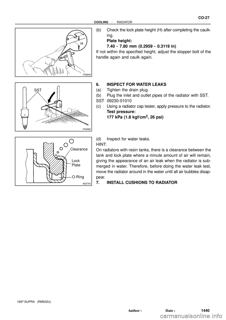
(b) Check the lock plate height (H) after completing the caulk-
ing.
Plate height:
7.40 - 7.80 mm (0.2959 - 0.3119 in)
If not within the specified height, adjust the stopper bolt of the
handle again and caulk again.
6. INSPECT FOR WATER LEAKS
(a) Tighten the drain plug.
(b) Plug the inlet and outlet pipes of the radiator with SST.
SST 09230-01010
(c) Using a radiator cap tester, apply pressure to the radiator.
Test pressure:
177 kPa (1.8 kgf/cm
2, 26 psi)
(d) Inspect for water leaks.
HINT:
On radiators with resin tanks, there is a clearance between the
tank and lock plate where a minute amount of air will remain,
giving the appearance of an air leak when the radiator is sub-
merged in water. Therefore, before doing the water leak test,
move the radiator around in the water until all air bubbles disap-
pear.
7. INSTALL CUSHIONS TO RADIATOR
Page 555 of 1807

S04468
Stop Below 91°C
S04469
Below 91°C
ECT Switch
ConnectorDisconnect
CO090-01
S04470
Above 100°C
RotateThermometer
S04471
Ammeter
Battery
Fan Connector 2.5 - 4.5 A
- COOLINGELECTRIC COOLING FAN (2JZ-GTE)
CO-29
1442 Author�: Date�:
1997 SUPRA (RM502U)
ELECTRIC COOLING FAN
(2JZ-GTE)
ON-VEHICLE INSPECTION
1. CHECK COOLING FAN OPERATION WITH LOW
TEMPERATURE (Below 91°C (196°F))
(a) Turn the ignition switch ON.
(b) Check that the cooling fan stops.
If not, check the cooling fan relay and ECT switch, and check
for a separated connector or severed wire between the No.1 ra-
diator fan relay and ECT switch.
(c) Disconnect the ECT switch connector.
(d) Check that the cooling fan rotates.
If not, check the No.1 radiator relay, No.2 radiator fan relay,
cooling fan, fuses, and check for short circuit between the No.1
radiator fan relay and ECT switch.
(e) Reconnect the ECT switch connector.
2. CHECK COOLING FAN OPERATION WITH HIGH
TEMPERATURE (Above 100°C (212°F))
(a) Start the engine, and raise coolant temperature to above
100°C (212°F).
(b) Check that the cooling fan rotates.
If not, replace the ECT switch.
3. INSPECT COOLING FAN
(a) Disconnect the fan connector.
(b) Connect battery and ammeter to the cooling fan connec-
tor.
(c) Check that the cooling fan rotates smoothly, and check
the reading on the ammeter.
Standard amperage: 2.5 - 4.5 A
(d) Reconnect the fan connector.
Page 556 of 1807
CO091-02
S04927
Air Cleaner Duct
Upper Radiator Hose
Lower Radiator Hose
Radiator
Cap
Radiator Reservoir
Hose
No.5 Air Hose
Battery
Battery Tray Radiator
AssemblyHold-Down
Clamp
Battery Insulator Oil Cooler Hose (A/T)
Upper Radiator
Support
Electric Cooling
Fan Connector
No.2 Air Tube
Drain Plug
No.2 Fan ShroudClipECT Switch (for Electric
Cooling Fan) Connector Lower
Radiator
Support
� O-Ring
Electric Cooling Fan
RadiatorNo.1 Fan Shroud Engine Under Cover x16 2JZ-GTE
� O-Ring ECT Switch (for Electric Cooling Fan)
Drain Hose
� Non-reusable partLH Headlight Beam Angle Gauge CO-30
- COOLINGELECTRIC COOLING FAN (2JZ-GTE)
1443 Author�: Date�:
1997 SUPRA (RM502U)
COMPONENTS