Page 1478 of 1807

SF0GR-01
S04780
Engine Wire
Protector
Air Intake Chamber Stay
IAC Valve Connector
VSV Connector for EGR
Turbo Pressure Sensor Connector
VSV Connector for Fuel Pressure Control
Water Bypass HoseControl Cable Bracket and Cable
Vacuum HoseIAC Valve Pipe
EVAP Hose
� Gasket
EGR Pipe
Brake Booster
Vacuum Hose
Engine
Wire
Protector
Engine Wire Bracket
Engine Wire ClampGround
Cable
EGR Gas Temperature
Sensor Connector
Manifold Stay
No.4 Water Bypass Pipe
Water Bypass Hose Air Intake
Chamber
PS Air Hose Injector Connector
Engine Wire
Clamp
� InsulatorInjector � O - Ring
Vacuum Sensing Hose
Spacer
Delivery Pipe
Fuel Return Pipe
Sub-Throttle Position
Sensor ConnectorInjector Holder
x3
Fuel Inlet Pipe
PCV Hose
Oil Dipstick and Guide for A/T � Gasket
� Gasket
Air Hose
PS Air Hose
Water Bypass Hose
Sub - Throttle Actuator
Connector
Engine Under Cover � Gasket � Insulator
Spacer
Fuel Return Hose Throttle Body
Throttle Position
Sensor ConnectorOil Dipstick and Guide
for Engine� O - Ring
� O - Ring � Gasket
� Gasket
� Non - reusable part
- SFI (2JZ-GTE)INJECTOR
SF-19
1345 Author�: Date�:
1997 SUPRA (RM502U)
COMPONENTS
Page 1479 of 1807

SF0GS-02
P12565
Pull
O-Ring
S00910
Engine Wire Clamp
O-Ring
Pull
Fuel
Return
Hose
P11322
Chamber
StagCable
Bracket
P11321(1) (2) (3)(4) SF-20
- SFI (2JZ-GTE)INJECTOR
1346 Author�: Date�:
1997 SUPRA (RM502U)
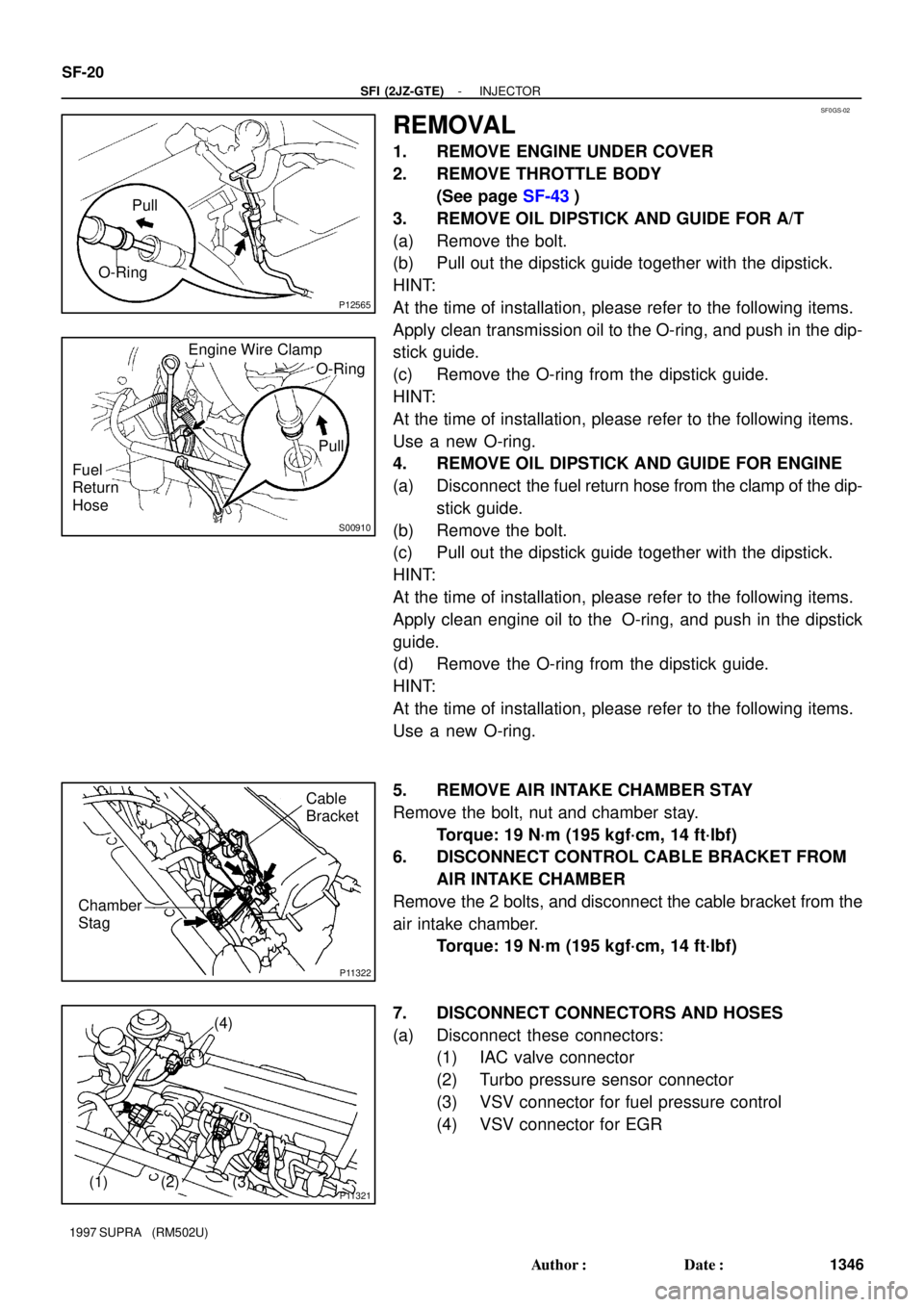
REMOVAL
1. REMOVE ENGINE UNDER COVER
2. REMOVE THROTTLE BODY
(See page SF-43)
3. REMOVE OIL DIPSTICK AND GUIDE FOR A/T
(a) Remove the bolt.
(b) Pull out the dipstick guide together with the dipstick.
HINT:
At the time of installation, please refer to the following items.
Apply clean transmission oil to the O-ring, and push in the dip-
stick guide.
(c) Remove the O-ring from the dipstick guide.
HINT:
At the time of installation, please refer to the following items.
Use a new O-ring.
4. REMOVE OIL DIPSTICK AND GUIDE FOR ENGINE
(a) Disconnect the fuel return hose from the clamp of the dip-
stick guide.
(b) Remove the bolt.
(c) Pull out the dipstick guide together with the dipstick.
HINT:
At the time of installation, please refer to the following items.
Apply clean engine oil to the O-ring, and push in the dipstick
guide.
(d) Remove the O-ring from the dipstick guide.
HINT:
At the time of installation, please refer to the following items.
Use a new O-ring.
5. REMOVE AIR INTAKE CHAMBER STAY
Remove the bolt, nut and chamber stay.
Torque: 19 N´m (195 kgf´cm, 14 ft´lbf)
6. DISCONNECT CONTROL CABLE BRACKET FROM
AIR INTAKE CHAMBER
Remove the 2 bolts, and disconnect the cable bracket from the
air intake chamber.
Torque: 19 N´m (195 kgf´cm, 14 ft´lbf)
7. DISCONNECT CONNECTORS AND HOSES
(a) Disconnect these connectors:
(1) IAC valve connector
(2) Turbo pressure sensor connector
(3) VSV connector for fuel pressure control
(4) VSV connector for EGR
Page 1568 of 1807

P25789
40 mm
Contact
Plate 20 mm
37 mmWooden
Block
(kgf/cm2) =Ram diameter (cm)
100 kgf
2x 3.14 (p)
2
(psi) =Ram diameter (in.)
221 lbf
2x 3.14 (p)
2
(kPa) = (kgf/cm2) x 98.1
(kPa) = (psi) x 6.9
P25790
SST
P25791
ST-12
- STARTINGSTARTER
1519 Author�: Date�:
1997 SUPRA (RM502U)
(f) Temporarily tighten the terminal nuts.
(g) Tighten the terminal nut
(1) Put a wooden block on the contact plate and press
it down with a hand press.
Dimensions of wooden block:
20 x 37 x 40 mm (0.79 x 1.46 x 1.57 in.)
Press force:
981 N (100 kgf, 221 lbf)
NOTICE:
�Check the diameter of the hand press ram. Then
calculate the gauge pressure of the press when
981 N (100 kgf, 221 lbf) of force is applied.
Gauge pressure:
�If the contact plate is not pressed down with the spe-
cified pressure, the contact plate may tilt due to coil
deformation or the tightening of the nut.
(2) Using SST, tighten the nuts to the specified torque.
SST 09810-38140
Torque: 17 N´m (173 kgf´cm, 13 ft´lbf)
NOTICE:
If the nut is over tightened, it may cause cracks on the in-
side of the insulator.
(h) Clean the contact surfaces of the remaining contact plate
and plunger with a dry shop rag.
(i) Reinstall the plunger, new gasket, end cover and lead
clamp with the 3 bolts.
Torque: 2.5 N´m (26 kgf´cm, 22 in.´lbf)
Page 1575 of 1807

Z15498
PS GearOil
Reservior
PS Vane
Pump Closed
SST
Z15499
PS GearOil
Reservior
PS Vane
Pump
SST Open
Z15500
PS GearOil
Reservior
PS Vane
Pump
SST Open SR-6
- STEERINGPOWER STEERING FLUID
1890 Author�: Date�:
1997 SUPRA (RM502U)
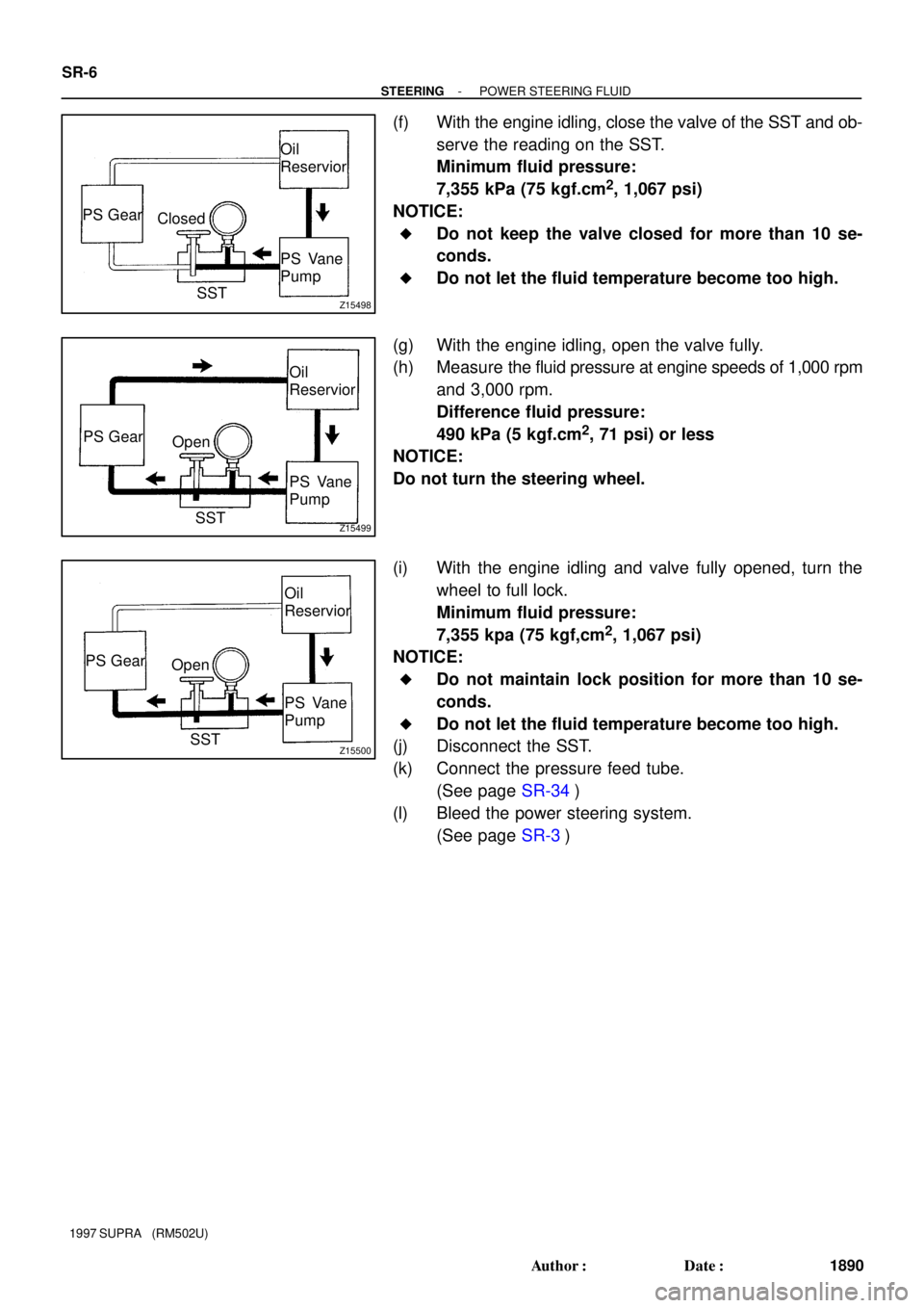
(f) With the engine idling, close the valve of the SST and ob-
serve the reading on the SST.
Minimum fluid pressure:
7,355 kPa (75 kgf.cm
2, 1,067 psi)
NOTICE:
�Do not keep the valve closed for more than 10 se-
conds.
�Do not let the fluid temperature become too high.
(g) With the engine idling, open the valve fully.
(h) Measure the fluid pressure at engine speeds of 1,000 rpm
and 3,000 rpm.
Difference fluid pressure:
490 kPa (5 kgf.cm
2, 71 psi) or less
NOTICE:
Do not turn the steering wheel.
(i) With the engine idling and valve fully opened, turn the
wheel to full lock.
Minimum fluid pressure:
7,355 kpa (75 kgf,cm
2, 1,067 psi)
NOTICE:
�Do not maintain lock position for more than 10 se-
conds.
�Do not let the fluid temperature become too high.
(j) Disconnect the SST.
(k) Connect the pressure feed tube.
(See page SR-34)
(l) Bleed the power steering system.
(See page SR-3)
Page 1592 of 1807
SR143-01
Z18268
2JZ-GE:
PS Vane Pump
AssemblyOil ReservoirReturn Tube
Battery Clamp
Battery Cover
� Terminal
� Terminal Pressure Feed Tube Air Control Valve
� Gasket
Union Bolt
Drive Belt
Battery
Battery Carrier
Engine Under Cover
x10
� Non-reusable part
- STEERINGPOWER STEERING VANE PUMP
SR-23
1907 Author�: Date�:
1997 SUPRA (RM502U)
POWER STEERING VANE PUMP
COMPONENTS
Page 1593 of 1807
Z18269
2JZ-GTE:
Battery Clamp
Battery Cover
� Terminal
� Terminal
Battery Pressure Feed Tube
� GasketUnion Bolt Drive Belt
Battery Carrier Air Hose No.5
Oil Reservoir to
Pump Hose
PS Vane Pump Assembly
Vane Pump Pulley
Engine Under Cover
x10
� Non-reusable part SR-24
- STEERINGPOWER STEERING VANE PUMP
1908 Author�: Date�:
1997 SUPRA (RM502U)
Page 1594 of 1807
Z19281
2JZ-GE and 2JZ-GTE:
Reservoir Cap2JZ-GE:
Oil Reservoir
2JZ-GTE:
Suction Port Union
� O-Ring
Flow Control Valve
Pressure Port
Union Front Housing
Vane Pump Shaft
2JZ-GE:
Vane Pump Pulley� O-Ring
� Bearing� Oil Seal� Gasket
Spring
� O-Ring
� Snap Ring
� Snap Ring
� O-Ring
� Straight Pin
Rear Housing Wave Washer
Side Plate
Cam Ring
Vane Plate Vane Pump Rotorx10
� Straight Pin
� Non-reusable part
: Power steering fluid
- STEERINGPOWER STEERING VANE PUMP
SR-25
1909 Author�: Date�:
1997 SUPRA (RM502U)
Page 1595 of 1807

SR144-01
R06091
R07429
R07432
SR-26
- STEERINGPOWER STEERING VANE PUMP
1910 Author�: Date�:
1997 SUPRA (RM502U)
REMOVAL
1. REMOVE ENGINE UNDER COVER
Remove the 10 screws.
2. REMOVE BATTERY
(a) Disconnect the 2 terminals.
(b) Remove the bolt, nut and battery clamp.
(c) Remove the battery cover.
(d) Remove the battery and battery carrier.
3. 2JZ-GTE:
REMOVE AIR HOSE No.5
4. REMOVE DRIVE BELT
Loosen the drive belt tension by turning the drive belt tensioner
clockwise, and remove the drive belt.
5. 2JZ-GTE:
DISCONNECT OIL RESERVOIR TO PUMP HOSE
Remove the clip and disconnect the hose.
NOTICE:
Take care not to spill fluid on the A/C compressor rotor.
6. 2JZ-GE:
DISCONNECT RETURN TUBE
NOTICE:
Take care not to spill fluid on the A/C compressor rotor.
7. 2JZ-GTE:
REMOVE VANE PUMP PULLEY
Using SST to stop the pulley rotating, remove the nut.
SST 09960-10010 (09962-01000, 09963-01000)
8. REMOVE PRESSURE FEED TUBE
Using a spanner (24 mm) to hold the pressure port union, re-
move the union bolt and gasket.
9. REMOVE PS VANE PUMP ASSEMBLY
Remove the 2 pump assembly set bolts.