Page 616 of 1807

DI-201
429 Author�: Date�:
1997 SUPRA (RM502U)
DTC P0171 System too Lean (Fuel Trim)
DTC P0172 System too Rich (Fuel Trim)
CIRCUIT DESCRIPTION
ºFuel trimº refers to t")
- DIAGNOSTICSENGINE (2JZ-GTE)
DI-201
429 Author�: Date�:
1997 SUPRA (RM502U)
DTC P0171 System too Lean (Fuel Trim)
DTC P0172 System too Rich (Fuel Trim)
CIRCUIT DESCRIPTION
ºFuel trimº refers to the feedback compensation value compared against the basic injection time. Fuel trim
includes short-term fuel trim and long-term fuel trim.
ºShort-term fuel trimº is the short-term fuel compensation used to maintain the air-fuel ratio at its ideal
theoretical value. The signal from the heated oxygen sensor indicates whether the air-fuel ratio is RICH or
LEAN compared to the ideal theoretical value, triggering a reduction in fuel volume if the air-fuel ratio is rich,
and an increase in fuel volume if it is lean.
ºLong-term fuel trimº is overall fuel compensation carried out long-term to compensate for continual devi-
ation of the short-term fuel trim from the central value due to individual engine differences, wear over time
and changes in the usage environment.
If both the short-term fuel trim and long-term fuel trim are LEAN or RICH beyond a certain value, it is de-
tected as a malfunction and the MIL lights up.
DTC No.DTC Detecting ConditionTrouble Area
P0171
When the air fuel ratio feedback is stable after engine warning
up, the fuel trim is considerably in error on the RICH side
(2 trip detection logic)
�Air intake (hose loose)
�Fuel line pressure
�Injector blockage
�Heated oxygen sensor malfunction
�Mass air flow meter
�Engine coolant temp. sensor
P0172
When the air fuel ratio feedback is stable after engine warning
up, the fuel trim is considerably in error on the LEAN side
(2 trip detection logic)
�Fuel line pressure
�Injector blockage, leak
�Heated oxygen sensor malfunction
�Mass air flow meter
�Engine coolant temp. sensor
HINT:
�When DTC P0171 is recorded, the actual air-fuel ratio is on the LEAN side. When DTC P0172 is re-
corded, the actual air-fuel ratio is on the RICH side.
�If the vehicle runs out of fuel, the air-fuel ratio is LEAN and DTC P0171 is recorded. The MIL then
comes on.
�If the total of the short-term fuel trim value and long-term fuel trim value is within ± 35 %, the system
is functioning normally.
INSPECTION PROCEDURE
1 Check air induction system (See page SF-1).
NG Repair or replace.
OK
DI4SY-01
Page 617 of 1807
DI-202
- DIAGNOSTICSENGINE (2JZ-GTE)
430 Author�: Date�:
1997 SUPRA (RM502U)
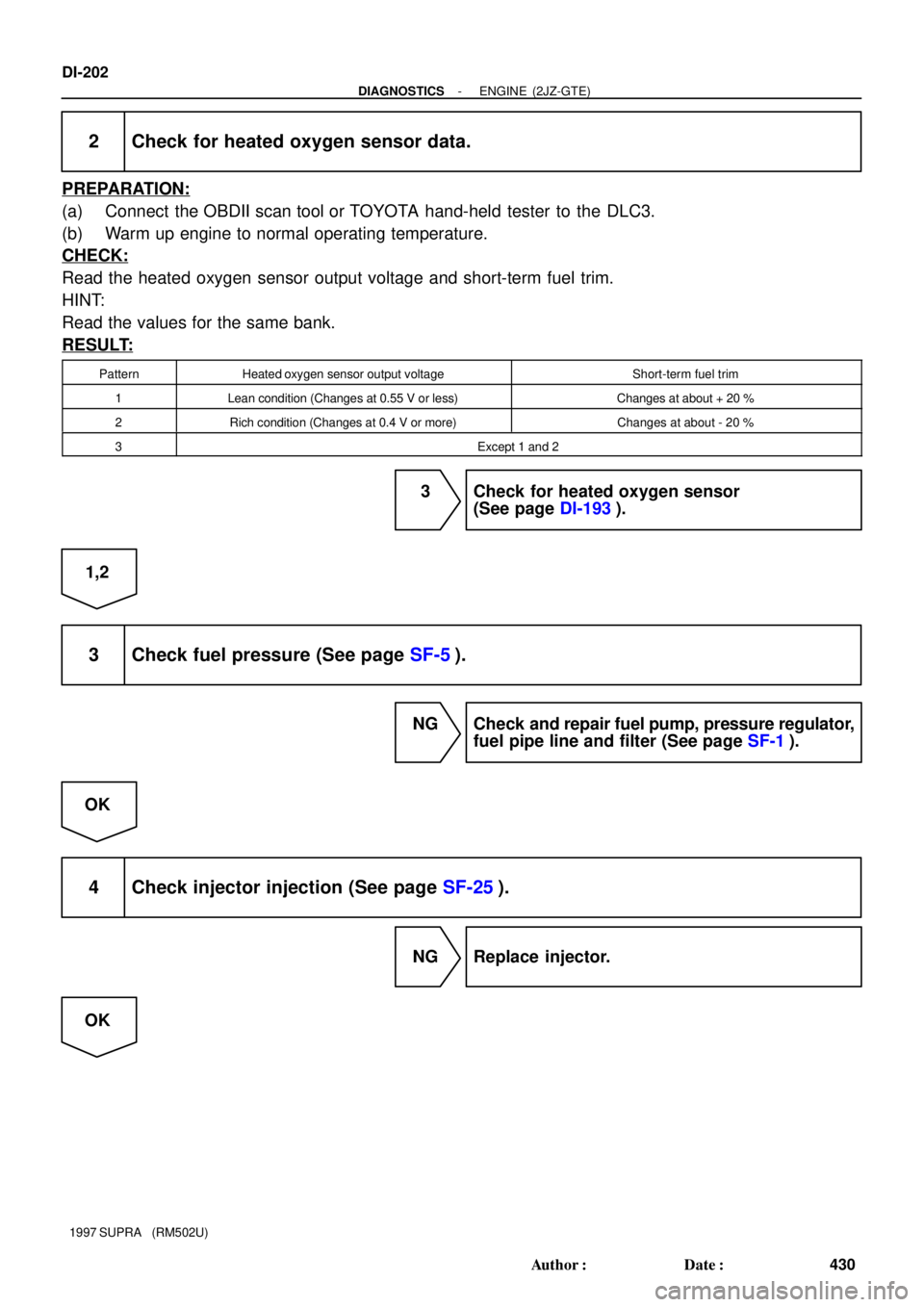
2 Check for heated oxygen sensor data.
PREPARATION:
(a) Connect the OBDII scan tool or TOYOTA hand-held tester to the DLC3.
(b) Warm up engine to normal operating temperature.
CHECK:
Read the heated oxygen sensor output voltage and short-term fuel trim.
HINT:
Read the values for the same bank.
RESULT:
PatternHeated oxygen sensor output voltageShort-term fuel trim
1Lean condition (Changes at 0.55 V or less)Changes at about + 20 %
2Rich condition (Changes at 0.4 V or more)Changes at about - 20 %
3Except 1 and 2
3 Check for heated oxygen sensor
(See page DI-193).
1,2
3 Check fuel pressure (See page SF-5).
NG Check and repair fuel pump, pressure regulator,
fuel pipe line and filter (See page SF-1).
OK
4 Check injector injection (See page SF-25).
NG Replace injector.
OK
Page 619 of 1807

432 Author�: Date�:
1997 SUPRA (RM502U)
DTC P0300 Random/Multiple Cylinder Misfire Detected
DTC P0301 Cylinder 1 Misfire Detected
DTC P0302 Cylinder 2 Misfire D")
DI-204
- DIAGNOSTICSENGINE (2JZ-GTE)
432 Author�: Date�:
1997 SUPRA (RM502U)
DTC P0300 Random/Multiple Cylinder Misfire Detected
DTC P0301 Cylinder 1 Misfire Detected
DTC P0302 Cylinder 2 Misfire Detected
DTC P0303 Cylinder 3 Misfire Detected
DTC P0304 Cylinder 4 Misfire Detected
DTC P0305 Cylinder 5 Misfire Detected
DTC P0306 Cylinder 6 Misfire Detected
CIRCUIT DESCRIPTION
Misfire: The ECM uses the crankshaft position sensor and camshaft position sensor to monitor changes in
the crankshaft rotation for each cylinder.
The ECM counts the number of times the engine speed change rate indicates that misfire has occurred.
When the misfire rate equals or exceeds the count indicating that the engine condition has deteriorated, the
MIL lights up.
If the misfire rate is high enough and the driving conditions will cause catalyst overheating, the MIL blinks
when misfiring occurs.
DTC No.DTC Detecting ConditionTrouble Area
P0300Misfiring of random cylinders is detected during the any
particular 200 or 1,000 revolutions�Ignition system
�Injector
P0301
P0302
P0303For any particular 200 revolutions of the engine, misfiring is
detected which can cause catalyst overheating (This causes
MIL to blink)
j
�Fuel line pressure
�EGR
�Compression pressure
�
Valve clearance not to specificationP0303
P0304
P0305
P0306For any particular 1,000 revolutions of the engine, misfiring
is detected which causes a deterioration in emission (2 trip
detection logic)
�Valve clearance not to specification
�Valve timing
�Mass air flow meter
�Engine coolant temp. sensor
HINT:
When the 2 or more codes for a misfiring cylinder are recorded repeatedly but no Random Misfire code is
recorded, it indicates that the misfires were detected and recorded at different times.
DI4SZ-01
Page 621 of 1807
P11799 IG0317 IG0151
A03065
1.1 mm
DI-206
- DIAGNOSTICSENGINE (2JZ-GTE)
434 Author�: Date�:
1997 SUPRA (RM502U)
INSPECTION PROCEDURE
1 Check spark plug and spark of misfiring cylinder.
PREPARATION:
(a) Remove the ignition coil (See page IG-6).
(b) Remove the spark plug.
CHECK:
(a) Check the carbon deposits on electrode.
(b) Check electrode gap.
OK:
(1) No large carbon deposit present.
Not wet with gasoline or oil.
(2) Electrode gap: 1.1 - 1.3 mm
(0.043 - 0.051 in.)
PREPARATION:
(a) Install the spark plug to the ignition coil, and connect the
ignition coil connector.
(b) Ground the spark plug.
(c) Disconnect injector connector.
CHECK:
Check if spark occurs while the engine is being cranked.
NOTICE:
To prevent excess fuel being injected from the injectors
during this test, don't crank the engine for more than 5 - 10
sec. at a time.
OK:
Spark jumps across electrode gap.
NG Replace or check ignition system (See page
IG-1).
OK
Page 622 of 1807
A00700
ON
Check Harness A
ECM
B20, 19, 18, 17, 16, 15
#10
(+)#20
(+)#30
(+)#40
(+)#50
(+)#60
(+)
- DIAGNOSTICSENGINE (2JZ-GTE)
DI-207
435 Author�: Date�:
1997 SUPRA (RM502U)
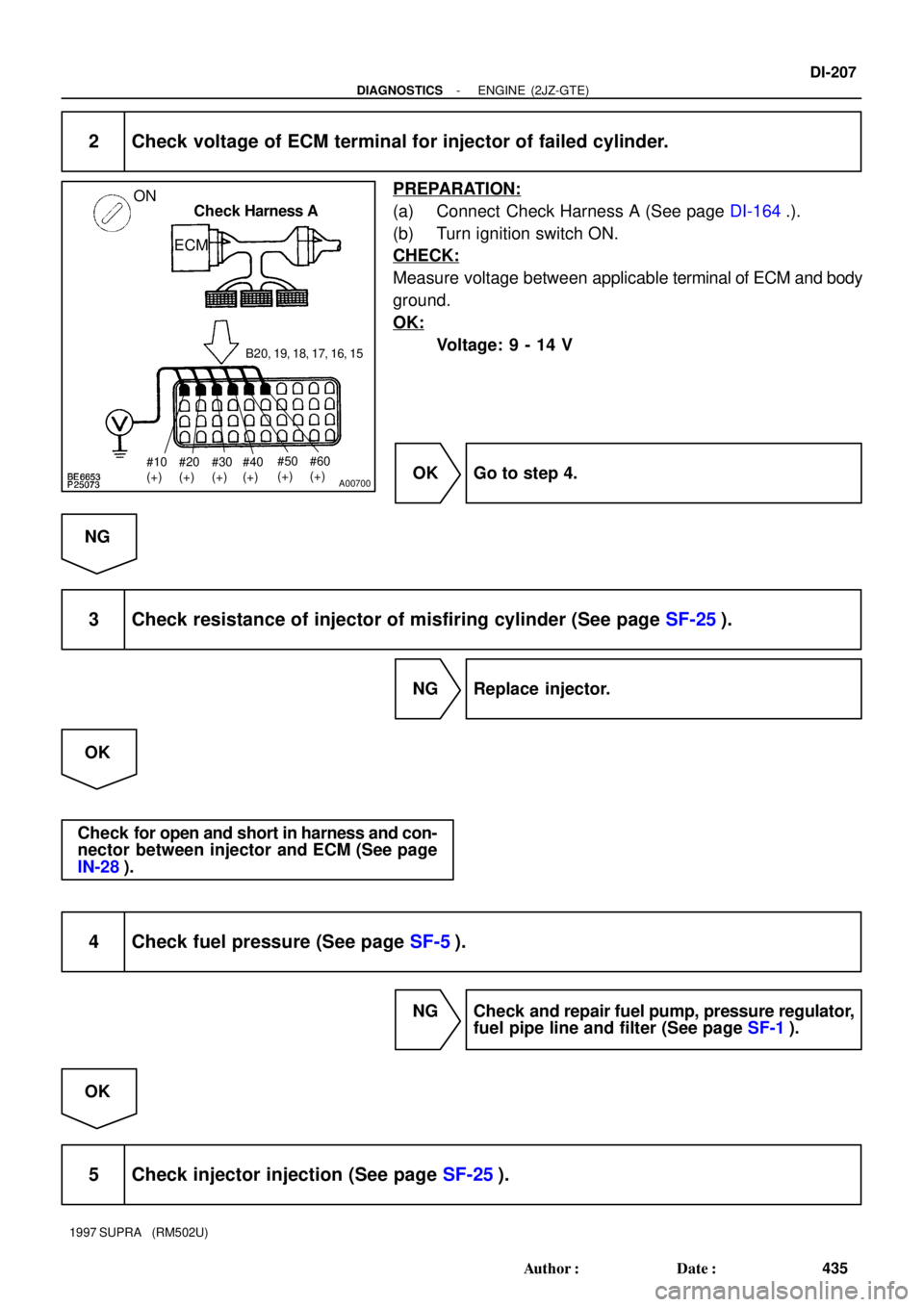
2 Check voltage of ECM terminal for injector of failed cylinder.
PREPARATION:
(a) Connect Check Harness A (See page DI-164.).
(b) Turn ignition switch ON.
CHECK:
Measure voltage between applicable terminal of ECM and body
ground.
OK:
Voltage: 9 - 14 V
OK Go to step 4.
NG
3 Check resistance of injector of misfiring cylinder (See page SF-25).
NG Replace injector.
OK
Check for open and short in harness and con-
nector between injector and ECM (See page
IN-28).
4 Check fuel pressure (See page SF-5).
NG Check and repair fuel pump, pressure regulator,
fuel pipe line and filter (See page SF-1).
OK
5 Check injector injection (See page SF-25).
Page 644 of 1807

DI-231
459 Author�: Date�:
1997 SUPRA (RM502U)
DTC P0420 Catalys")
FI7081
Waveform of oxygen sensor
before catalystNormal
catalystWaveform of oxygen sensor
after catalyst
- DIAGNOSTICSENGINE (2JZ-GTE)
DI-231
459 Author�: Date�:
1997 SUPRA (RM502U)
DTC P0420 Catalyst System Efficiency Below Threshold
CIRCUIT DESCRIPTION
The ECM compares the waveform of the oxygen sensor located before the catalyst with the waveform of
the oxygen sensor located after the catalyst to determine whether or not catalyst performance has deterio-
rated.
Air-fuel ratio feedback compensation keeps the waveform of the oxygen sensor before the catalyst repeat-
edly changing back and forth from rich to lean.
If the catalyst is functioning normally, the waveform of the oxygen sensor after the catalyst switches back
and forth between rich and lean much more slowly than the waveform of the oxygen sensor before the cata-
lyst.
But when both wavaforms change at a similar rate, it indicates that catalyst performance has deteriorated.
DTC No.DTC Detecting ConditionTrouble Area
P0420
After the engine and the catalyst are warmed up, and while the
vehicle is driven within the set vehicle and engine speed range,
the waveforms of the heated oxygen sensors (bank 1 sensor 1
and bank 1 sensor 2) have the same amplitude
(2 trip detection logic)
�Three-way catalytic converter
�Open or short in heated oxygen sensor circuit
�Heated oxygen sensor
DI4T5-01
Page 647 of 1807

S05422
To Turbo
Charcoal
Canister
Fuel Tank
ECMIntake Manifold VSV for
EVAP
S01079
Battery
EB
W-B
BB-W
R/B No.2
EFI No.1
EFI Main Relay
2 2A
2
2 2
2
35
1 2
B-R
B-YB-REA22VSV for EVAP
1274
B
ECM
EVAP
E01
B+
GR24
A
M-REL
V
EA18 1 DI-234
- DIAGNOSTICSENGINE (2JZ-GTE)
462 Author�: Date�:
1997 SUPRA (RM502U)
DTC P0441 Evaporative Emission Control System
Incorrect Purge Flow
CIRCUIT DESCRIPTION
To reduce HC emissions, evaporated fuel from the fuel tank is routed through the charcoal canister to the
intake manifold for combustion in the cylinders.
The ECM changes the duty signal to the VSV for EVAP so that the intake quantity of HC emissions is ap-
propriate for the driving conditions (engine load, engine speed, etc.) after the engine is warme up.
DTC No.DTC Detecting ConditionTrouble Area
P0441
The proper response to the computer command does not oc-
cur
(2 trip detection logic)
�Open or short in VSV circuit for EVAP
�VSV for EVAP
�Vacuum hose blocked or disconnected
�ECM
�Charcoal canister
WIRING DIAGRAM
DI4T6-01
Page 662 of 1807

DI-247
475 Author�: Date�:
1997 SUPRA (RM502U)
DTC P1100 Barometric Pressure Sensor Circuit
Malfunction
CIRCUIT DESCRIPTION
The BARO sensor is built into the ECM. This")
- DIAGNOSTICSENGINE (2JZ-GTE)
DI-247
475 Author�: Date�:
1997 SUPRA (RM502U)
DTC P1100 Barometric Pressure Sensor Circuit
Malfunction
CIRCUIT DESCRIPTION
The BARO sensor is built into the ECM. This is a semiconductor pressure sensor with properties which cause
its electrical resistance to change when stress is applied to the sensor's crystal (silicon) (piezoelectric effect).
This sensor is used to detect the atmospheric (absolute) pressure and outputs corresponding electrical sig-
nals. Fluctuations in the air pressure cause changes in the intake air density, which can cause deviations
in the air-fuel ratio. The signals from BARO sensor are used to make corrections for these fluctuations. If
the ECM detects DTC P1100, the fail safe function operates and the atmospheric pressure is set at a
constant 760 mmHg.
DTC No.DTC Detecting ConditionTrouble Area
P1100Open or short detected in barometric pressure sensor circuit
(2 trip detection logic)�ECM
INSPECTION PROCEDURE
1 Are there any other codes (besides DTC P1100) being output?
YES Go to relevant DTC chart.
NO
Replace ECM.
DI4TA-01